Pololu 1300 User manual

Pololu USB AVR Programmer
User’s Guide
Pololu USB AVR Programmer User’s Guide © 2001–2019 Pololu Corporation
https://www.pololu.com/docs/0J36/all Page 1 of 64

1. Overview . . . . . . . . . . . . . . . . . . . . . . . . . . . . . . . . . . . . . . . . . . . . . . 3
1.a. Module Pinout and Components . . . . . . . . . . . . . . . . . . . . . . . . . . . . . . 4
1.b. Supported Microcontrollers . . . . . . . . . . . . . . . . . . . . . . . . . . . . . . . . . 6
1.c. Supported Operating Systems . . . . . . . . . . . . . . . . . . . . . . . . . . . . . . . . 6
2. Contacting Pololu . . . . . . . . . . . . . . . . . . . . . . . . . . . . . . . . . . . . . . . . . . 8
3. Getting Started in Windows . . . . . . . . . . . . . . . . . . . . . . . . . . . . . . . . . . . . 9
3.a. Installing Windows Drivers and Software . . . . . . . . . . . . . . . . . . . . . . . . . . 9
3.b. Programming AVRs using Atmel Studio . . . . . . . . . . . . . . . . . . . . . . . . . . 14
3.b.1. Adding Devices to Atmel Studio 6 . . . . . . . . . . . . . . . . . . . . . . . . 20
3.b.2. Using Advanced Features of Atmel Studio . . . . . . . . . . . . . . . . . . . . 22
3.b.3. Faster programming with F5 in Atmel Studio . . . . . . . . . . . . . . . . . . . 24
3.c. Programming AVRs Using AVR Studio 4 . . . . . . . . . . . . . . . . . . . . . . . . . 25
3.c.1. Using Advanced Features of AVR Studio 4 . . . . . . . . . . . . . . . . . . . 34
3.d. Programming AVRs Using AVRDUD . . . . . . . . . . . . . . . . . . . . . . . . . . . 36
3.e. Configuring the Programmer . . . . . . . . . . . . . . . . . . . . . . . . . . . . . . . 37
4. Getting Started in Linux . . . . . . . . . . . . . . . . . . . . . . . . . . . . . . . . . . . . . 41
4.a. Linux Driver . . . . . . . . . . . . . . . . . . . . . . . . . . . . . . . . . . . . . . . . 41
4.b. Programming AVRs in Linux . . . . . . . . . . . . . . . . . . . . . . . . . . . . . . . . 41
5. Getting Started in Mac OS X . . . . . . . . . . . . . . . . . . . . . . . . . . . . . . . . . . . 44
5.a. Firmware Support for Mac OS X . . . . . . . . . . . . . . . . . . . . . . . . . . . . . 44
5.b. Determining serial port names in Mac OS X . . . . . . . . . . . . . . . . . . . . . . . 44
5.c. Programming AVRs in Mac OS X . . . . . . . . . . . . . . . . . . . . . . . . . . . . . 44
6. Communicating via the USB-to-TTL-Serial Adapter . . . . . . . . . . . . . . . . . . . . . . . 47
6.a. Communicating via the Serial Control Lines . . . . . . . . . . . . . . . . . . . . . . . . 49
7. Measuring Voltages Using the SLO-scope . . . . . . . . . . . . . . . . . . . . . . . . . . . . 53
8. Troubleshooting . . . . . . . . . . . . . . . . . . . . . . . . . . . . . . . . . . . . . . . . . 56
9. Upgrading Firmware . . . . . . . . . . . . . . . . . . . . . . . . . . . . . . . . . . . . . . . 60
Pololu USB AVR Programmer User’s Guide © 2001–2019 Pololu Corporation
Page 2 of 64

1. Overview
The Pololu USB AVR programmer [https://www.pololu.com/product/1300] is a programmer for Atmel’s
AVR microcontrollers and controller boards based on these MCUs, such as Pololu Orangutan robot
controllers [https://www.pololu.com/category/8/robot-controllers] and the 3pi robot [https://www.pololu.com/
product/975]. The programmer emulates an STK500 on a virtual serial port, making it compatible
with standard AVR programming software. Two additional features help with building and debugging
projects: a TTL-level serial port for general-purpose communication and a SLO-scope for monitoring
signals and voltage levels.
Please note that this guide applies to Pololu’s second-generation AVR programmer (pictured to the left
below), not the original, similar-looking Orangutan USB programmer [https://www.pololu.com/product/
740] (pictured to the right).
USB AVR programmer PGM03A. Orangutan USB programmer PGM02A/B.
If you have the original Orangutan USB programmer, you can find it’s user’s guide here
[https://www.pololu.com/docs/0J6].
Important Safety Warning and Handling Procedures
The USB AVR programmer is not intended for young children! Younger users should use this product
only under adult supervision. By using this product, you agree not to hold Pololu liable for any injury
or damage related to the use or to the performance of this product. This product is not designed for,
and should not be used in, applications where the malfunction of the product could cause injury or
damage. Please take note of these additional precautions:
• The USB AVR programmer contains lead, so follow appropriate handling procedures, such
as washing hands after handling.
• Since the PCB and its components are exposed, take standard precautions to protect
Pololu USB AVR Programmer User’s Guide © 2001–2019 Pololu Corporation
1. Overview Page 3 of 64

your programmer from SD (electrostatic discharge), such as first touching the surface the
programmer is resting on before picking it up. When handing the programmer to another
person, first touch their hand with your hand to equalize any charge imbalance between you
so that you don’t discharge through the programmer as the exchange is made.
1.a. Module Pinout and Components
Pololu USB AVR programmer, labeled top view.
The Pololu USB AVR programmer connects to a computer’s USB port via an included USB A to
mini-B cable, and it connects to the target device via an included 6-pin ISP programming cable
[https://www.pololu.com/product/972] (the older, 10-pin ISP connections are not directly supported, but it is
easy to create or purchase a 6-pin-to-10-pin ISP adapter).
The USB AVR programmer has three indicator L Ds:
• The green LED indicates the USB status of the device. When you connect the programmer
to the computer via the USB cable, the green L D will start blinking slowly. The blinking
continues until it receives a particular message from the computer indicating that the drivers
are installed correctly. After the programmer gets this message, the green L D will be on, but
it will flicker briefly when there is USB activity.
Pololu USB AVR Programmer User’s Guide © 2001–2019 Pololu Corporation
1. Overview Page 4 of 64

• The yellow LED indicates that the programmer is doing something. When it is blinking, it
means that the programmer has detected the target device (the voltage on the target VDD
line is high). When it is on solid, it means that the SLO-scope is enabled, and lines Aand B
are used for the SLO-scope instead of the USB-to-TTL-serial adapter.
• The red LED indicates an error or warning. When it is blinking, it means that the target device
is not detected (the voltage on the target VDD line is low). When it is on solid, it means that
the last attempt at programming resulted in an error. You can determine the source of the
error by running the configuration utility (see Section 3.e).
The VBUS line provides direct access to the 5V VBUS line on the USB cable and can be used to
power additional devices. The line can provide up to 100 mA, so the current draw of your programmer
plus any additional devices should not exceed this amount. If you attempt to draw more than this limit,
your computer might disconnect the USB port temporarily or take other actions to limit the use of USB
power.
The GND line provides direct access to the grounded line on the USB cable (and ground on the
programmer).
The TX and RX lines are the TTL serial port for the USB-to-TTL-serial adapter. They are labeled from
the computer’s perspective: TX is an output that connects to your target’s serial receive pin and RX is
an input that connects to your target’s serial transmit pin. Section 6 describes how to use these lines
to communicate with your devices from the computer.
The Aand Blines can be used as serial control/handshaking lines for the USB-to-TTL-serial adapter
(see Section 6.a) or as analog voltage inputs for the SLO-scope (see Section 7).
Pololu USB AVR programmer bottom view with
dimensions.
Pololu USB AVR Programmer User’s Guide © 2001–2019 Pololu Corporation
1. Overview Page 5 of 64

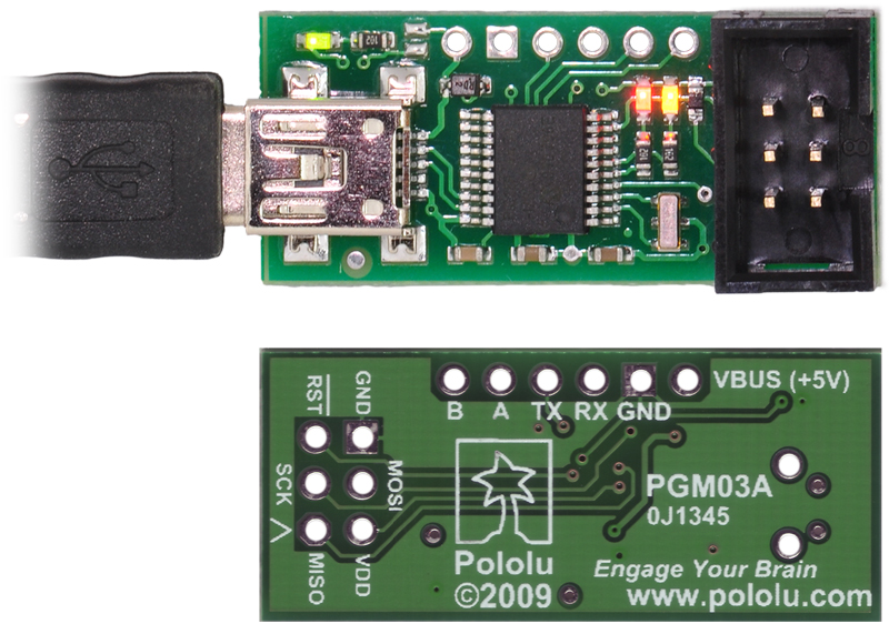
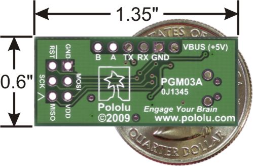
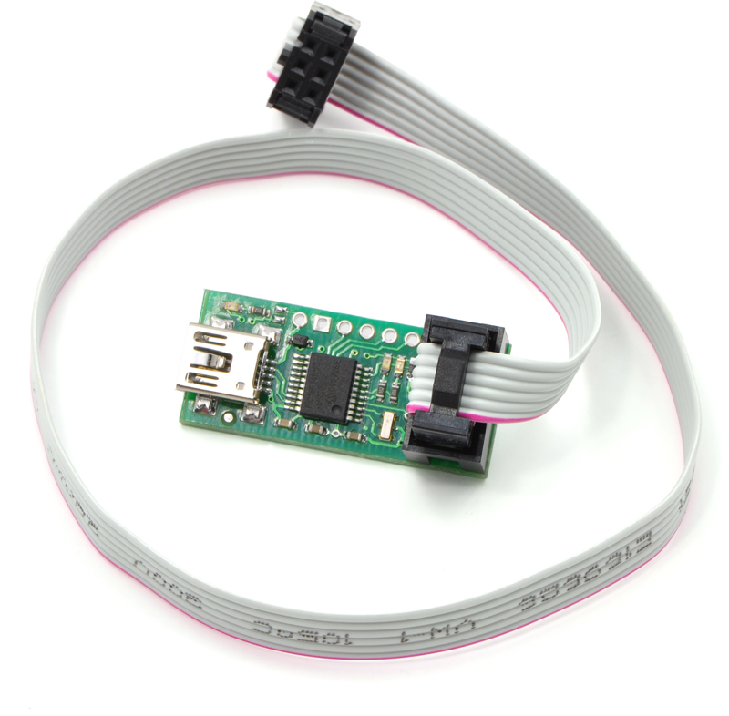
The USB AVR programmer has a standard 6-pin AVR ISP connector for programming AVRs, and the
pins are labeled on the silkscreen on the bottom side of the board. The pins on the connector are:
1. MISO: The “Master Input, Slave Output” line for SPI communication with the target AVR. The
programmer is the master, so this line is an input.
2. VDD: An input line that the programmer uses to measure the voltage of the target AVR.
While programming the target device, the programmer uses this line to constantly monitor
the target VDD. If the voltage goes too low or varies too much, then the programmer aborts
programming in order to avoid damage to the target AVR. Section 3.e has more information
about target VDD monitoring. The VDD line is not used to power the programmer; the
programmer is powered from the USB. This line cannot be used to power the target device;
the target device must be independently powered for programming to work.
3. SCK: The clock line for SPI communication with the target AVR. The programmer is the
master, so this line is an output during programming.
4. MOSI: The “Master Output, Slave Input” line for SPI communication with the target AVR. The
programmer is the master, so this line is an output during programming.
5. RST: The target AVR’s reset line. This line is used as an output driven low during
programming to hold the AVR in reset.
6. GND: Ground. This line should be connected to the target device’s ground.
1.b. Supported Microcontrollers
The programmer should work with all AVRs that can be programmed with the AVR ISP interface,
but it has not been tested on all devices. It has been tested with all Orangutan robot controllers
[https://www.pololu.com/category/8/robot-controllers] and the 3pi Robot [https://www.pololu.com/product/975].
The programmer features upgradable firmware, allowing updates for future devices. It does not
currently work with Atmel’s XMega line of microcontrollers.
The programmer is powered by the 5V USB power bus, and it is intended for programming AVRs that
are running at close to 5 V (note that the programmer does not deliver power to the target device).
1.c. Supported Operating Systems
We support using the Pololu USB AVR Programmer on Windows Vista, Windows 7, Windows 8,
Windows 10, Linux, and Mac OS X.
The programmer’s configuration utility works only in Windows, but this should not be a big problem for
Linux users because all the options that can be set in the configuration utility are stored in persistent
memory, so you would only have to use Windows when you want to change those parameters, which
should be rarely (if ever). The programmer does not require the configuration to program AVRs or to
Pololu USB AVR Programmer User’s Guide © 2001–2019 Pololu Corporation
1. Overview Page 6 of 64

use the TX and RX USB-to-TTL-serial adapter pins.
The SLO-scope application works only in Windows.
The programmer is compatible with a variety of AVR programming utilities for Windows, Linux and
Mac OS, including AVRDUD , AVR Studio 4, AVR Studio 5, and Atmel Studio.
Pololu USB AVR Programmer User’s Guide © 2001–2019 Pololu Corporation
1. Overview Page 7 of 64

2. Contacting Pololu
You can check the Pololu USB AVR programmer page
[https://www.pololu.com/product/1300] for additional information. We
would be delighted to hear from you about any of your projects
and about your experience with the Pololu USB AVR
Programmer. You can contact us [https://www.pololu.com/contact]
directly or post on our forum [http://forum.pololu.com/]. Tell us what
we did well, what we could improve, what you would like to see in
the future, or anything else you would like to say!
Pololu USB AVR Programmer User’s Guide © 2001–2019 Pololu Corporation
2. Contacting Pololu Page 8 of 64

3. Getting Started in Windows
3.a. Installing Windows Drivers and Software
If you use Windows XP, you will need to have either Service Pack 3
[http://www.microsoft.com/downloads/details.aspx?FamilyId=68C48DAD-
BC34-40BE-8D85-6BB4F56F5110] or Hotfix KB918365 installed before installing the drivers
for the Pololu USB AVR programmer. Some users who installed the hotfix have reported
problems using the programmer which were solved by upgrading to Service Pack 3, so
we recommend Service Pack 3 over the hotfix.
Please note that these drivers will only work for the USB AVR programmer; if you have Pololu’s original
Orangutan USB programmer [https://www.pololu.com/product/740], you will need to install the drivers
specific to that device.
Before you connect your Pololu USB AVR programmer to a computer running Microsoft Windows, you
must install its drivers:
1. Download and install the Pololu AVR Development Bundle [https://www.pololu.com/file-redirect/
avr-development-bundle] (~11 MB exe). This includes the drivers and software for the Pololu
USB AVR Programmer, along with the Pololu AVR C/C++ Library and the Orangutan SVP
Drivers. If you are not sure which of these components you need, it is OK to install all
of them. If you only need to install the drivers and software for the programmer, you
can download those separately: USB AVR Programmer Windows Drivers and Software
[https://www.pololu.com/file/0J486/pololu-usb-avr-programmer-win-121114.exe] (11MB exe).
2. During the installation, Windows will ask you if you want to install the drivers. Click “Install”
(Windows 10, 8, 7, and Vista) or “Continue Anyway” (Windows XP).
Pololu USB AVR Programmer User’s Guide © 2001–2019 Pololu Corporation
3. Getting Started in Windows Page 9 of 64

Windows 10, Windows 8, Windows 7, and Windows Vista users: After the installation has finished,
your computer should automatically install the necessary drivers when you connect a Pololu USB AVR
programmer, in which case no further action from you is required.
Windows XP users: After the installation has finished, follow steps 3-7 for each new Pololu USB AVR
programmer you connect to your computer.
3. Connect the USB AVR programmer to your computer’s USB port. The programmer is
actually three devices in one so your XP computer will detect all three of those new
devices and display the “Found New Hardware Wizard” three times. ach time the
“Found New Hardware Wizard” pops up, follow steps 4-7.
4. When the “Found New Hardware Wizard” is displayed, select “No, not this time” and click
“Next”.
5. On the second screen of the “Found New Hardware Wizard”, select “Install the software
automatically” and click “Next”.
Pololu USB AVR Programmer User’s Guide © 2001–2019 Pololu Corporation
3. Getting Started in Windows Page 10 of 64

6. Windows XP will warn you again that the driver has not been tested by Microsoft and
recommend that you stop the installation. Click “Continue Anyway”.
7. When you have finished the “Found New Hardware Wizard”, click “Finish”. After that, another
wizard will pop up. You will see a total of three wizards when plugging in the programmer.
Follow steps 4-7 for each wizard.
Pololu USB AVR Programmer User’s Guide © 2001–2019 Pololu Corporation
3. Getting Started in Windows Page 11 of 64

If you use Windows XP and experience problems installing the serial port drivers, the cause of your
problems might be a bug in older versions of Microsoft’s usb-to-serial driver usbser.sys. Versions
of this driver prior to version 5.1.2600.2930 will not work with the USB AVR programmer. You
can check what version of this driver you have by looking in the “Details” tab of the “Properties”
window for C:\Windows\System32\drivers\usbser.sys. To get the fixed version of the driver, you will
need to either install Service Pack 3 [http://www.microsoft.com/downloads/details.aspx?FamilyId=68C48DAD-
BC34-40BE-8D85-6BB4F56F5110] or Hotfix KB918365. Some users who installed the hotfix have reported
problems using the programmer which were solved by upgrading to Service Pack 3, so we recommend
Service Pack 3 over the hotfix.
After installing the drivers, if you go to your computer’s Device Manager and expand the “Ports (COM
& LPT)” list, you should see two COM ports: “Pololu USB AVR Programmer Programming Port” and
“Pololu USB AVR Programmer TTL Serial Port”. In parentheses after these names, you will see the
name of the port (e.g. “COM3” or “COM4”). If you expand the “Pololu USB Devices” list you should
see an entry for the Pololu USB AVR programmer.
Pololu USB AVR Programmer User’s Guide © 2001–2019 Pololu Corporation
3. Getting Started in Windows Page 12 of 64

Windows XP device manager showing the Pololu USB AVR
Programmer
Windows 8 device manager showing the Pololu USB AVR Programmer
The COM ports in the Device Manager might actually be named “USB Serial Device” instead of having
a descriptive name as shown in the screenshots above. This can happen if you are using Windows
10 or later and you plugged the programmer into your computer before installing our drivers for it.
In that case, Windows will set up your programmer using usbser.inf, a driver from Microsoft that
ships with Windows 10 and later, and it will display “USB Serial Device” as the name for each port.
The ports will be usable, but it will be hard to distinguish the ports from each other because of the
generic name shown in the Device Manager. We recommend fixing the names in the Device Manager
by right-clicking on each “USB Serial Device” entry, selecting “Update Driver Software…”, and then
selecting “Search automatically for updated driver software”. Windows should find the drivers you
already installed, which contain the correct name for the port.
Pololu USB AVR Programmer User’s Guide © 2001–2019 Pololu Corporation
3. Getting Started in Windows Page 13 of 64

Some software will not allow connection to higher COM port numbers. In particular, AVR Studio and
early versions of Atmel Studio cannot connect to ports higher than COM9. If you need to change the
COM port number assigned to your programmer, you can do so using the Device Manager. Double-
click the COM port to open the properties dialog, and click the “Advanced…” button in the “Port
Settings” tab. From this dialog you can change the COM port assigned to the programmer.
Once your have successfully installed the device drivers and software, you can run the Pololu USB
AVR Programmer Configuration Utility, which is available in the Start menu in the Pololu folder. This
application allows you to change many of the settings of your programmer and can help troubleshoot
problems. Please see Section 3.e for more information.
This software package also contains the installation files for the Pololu SLO-scope application for
Windows. Please see Section 7 for usage instructions.
3.b. Programming AVRs using Atmel Studio
If you have an Orangutan or 3pi Robot or wish to use the Pololu AVR C/C++ Library
for some other reason, we recommend following the Pololu AVR Programming Quick
Start Guide [https://www.pololu.com/docs/0J51] instead of this tutorial.
The following tutorial covers the steps needed to program AVRs in Windows using Atmel Studio
[https://www.microchip.com/avr-support/atmel-studio-7] and a Pololu USB AVR Programmer. Atmel Studio is
a free integrated development environment (ID ) provided by Atmel. In this tutorial, we will write a
simple program to blink an L D connected to pin PD1 of an AVR. If you want to program an AVR that
does not have an L D connected to pin PD1, the code in this tutorial can be modified.
You will need to:
• Download and install Atmel Studio [https://www.microchip.com/avr-support/atmel-studio-7] by
following the instructions on Atmel’s website. If you use Windows Vista, you should download
Atmel Studio 6.2, because that is latest version that supports Windows Vista. This tutorial
was written for Atmel Studio 7.0 and Atmel Studio 6.2.
• Install the Pololu USB AVR Programmer’s drivers on your computer. See Section 3.a for
instructions.
• Upgrade your programmer’s firmware to version 1.07 or later if necessary. See Section 9 for
instructions. If your programmer was shipped from Pololu after 2012-02-29, then you already
have the right firmware.
• If you are using Atmel Studio 6 or older, you might need to add an XML file to Atmel Studio
to make it support the AVR you wish to program. See Section 3.b.1 for instructions.
Pololu USB AVR Programmer User’s Guide © 2001–2019 Pololu Corporation
3. Getting Started in Windows Page 14 of 64

After you have completed these prerequisites, you can create a new Atmel Studio project:
1. Open Atmel Studio and click New Project. In the New Project dialog, select GCC C
Executable Project for the template. nter the project name and location. In this tutorial,
we will name our project “BlinkL D” and put it in the “C:\” directory, but you can choose a
different name and location if you would like. Uncheck the Create directory for solution box
to simplify the directory structure of your project. Click OK.
The New Project dialog of Atmel Studio 6.
2. In the Device Selection window, select the device name of your specific AVR. Click OK to
create the project.
Pololu USB AVR Programmer User’s Guide © 2001–2019 Pololu Corporation
3. Getting Started in Windows Page 15 of 64

The Device Selection dialog of Atmel Studio 6.
3. Remove the template code that was automatically placed in BlinkL D.c and replace it with
the code below:
Note: The value of F_CPU should be the clock frequency of your AVR in units of Hz,
so if your AVR is not running at 20 MHz you will need to change that line. If you do not
make this change, the timing of _delay_ms() will be off, but the L D will still blink.
4. Click the Build Solution button on the toolbar (or press F7) to compile the code.
1
2
3
4
5
6
7
8
9
10
11
12
13
#define F_CPU 20000000 // AVR clock frequency in Hz, used by util/delay.h
#include <avr/io.h>
#include <util/delay.h>
int main() {
DDRD |= (1<<DDD1); // set LED pin PD1 to output
while (1) {
PORTD |= (1<<PORTD1); // drive PD1 high
_delay_ms(100); // delay 100 ms
PORTD &= ~(1<<PORTD1); // drive PD1 low
_delay_ms(900); // delay 900 ms
}
}
?
Pololu USB AVR Programmer User’s Guide © 2001–2019 Pololu Corporation
3. Getting Started in Windows Page 16 of 64

Building a project with Atmel Studio 6.
5. Make sure your USB AVR programmer is connected to your computer via its USB A to mini-
B cable and then select Add target… from the Tools menu. Select STK500 as the tool.
Select the COM port that has been assigned to the programmer’s programming port, and
click Apply. If you are not sure which COM port to select, look in the Device Manager under
the “Ports (COM & LPT)” list. This step can be skipped if you have done it before.
Pololu USB AVR Programmer User’s Guide © 2001–2019 Pololu Corporation
3. Getting Started in Windows Page 17 of 64

The “Add target” dialog box in Atmel Studio 6.
6. Click the Device Programming button on the toolbar. You can also select Device
Programming from the Tools menu.
7. This will bring up the Device Programming dialog. For the Tool, select the STK500 that you
added earlier. Select the same device you selected earlier. If your device is not in the list, you
might need to add it to the list by following the instructions in Section 3.b.1. For the Interface,
select ISP. Click Apply.
Pololu USB AVR Programmer User’s Guide © 2001–2019 Pololu Corporation
3. Getting Started in Windows Page 18 of 64

Selecting a programmer, device, and interface in the Device
Programming dialog of Atmel Studio 6.
If you got an error that says “Unable to connect to tool STK500” and you see an error message in
the Output pane in the main window that says “The signature of the attached tool is AVRISP_2, which
is unexpected.” then you need to upgrade your programmer’s firmware to version 1.07 or later (see
Section 9). If you get a different error, see Troubleshooting (Section 8) for help identifying and fixing
the problem.
8. If you have not done so already, connect the programmer to the target device using the 6-pin
ISP cable. Make sure the cable is oriented so that pin 1 on the connector lines up with pin 1
on your target device, and that the target device is powered on. You can test the connection
by clicking the Read button next to the Device Signature box. This sends a command to the
target AVR asking for its signature. If everything works correctly, you should see a number
in hex notation appear in the Device Signature box. If you get an error about the signature
being wrong, you might have selected the wrong device. If you get a warning that says “Read
voltage … is outside selected device’s operating range” then double check to make sure that
your device is powered and that you have upgraded the programmer to firmware version 1.07
or later. For more help getting your connection working, see Troubleshooting (Section 8).
Reading the device signature of an AVR in Atmel
Studio 6.
9. Now it is time to program your target device. Select the Memories section on the left. The
Flash box should contain the path to the LF file that was generated when you built your
program. If it does not, you can browse for this using the “…” button to the right of the text
box. If you navigate to your project’s folder, you should find it as “Debug\<project name>.elf”.
Pololu USB AVR Programmer User’s Guide © 2001–2019 Pololu Corporation
3. Getting Started in Windows Page 19 of 64

Click the Program button in the Flash box.
The Memories section of the Device Programming dialog in Atmel Studio 6.
As your USB AVR Programmer programs the AVR, you should see all three L Ds flicker and you
should see the following text appear at the bottom of the window:
Erasing device... OK
Programming Flash...OK
Verifying Flash...OK
If there were no problems, the L D connected to PD1 of your AVR should now be flashing! Note that if
you are trying this on a 3pi robot and you have not yet soldered in the optional through-hole L Ds, the
flashing L D will be on the bottom of the robot. If there was a problem, please see Troubleshooting
(Section 8) for help identifying and fixing it.
3.b.1. Adding Devices to Atmel Studio 6
Pololu USB AVR Programmer User’s Guide © 2001–2019 Pololu Corporation
3. Getting Started in Windows Page 20 of 64
Table of contents
Other Pololu Motherboard manuals