Pololu USB AVR User manual

Pololu USB AVR
Programmer User's Guide
1. Overview . . . . . . . . . . . . . . . . . . . . . . . . . . . . . . . . . . . . . . . . . 2
1.a. Module Pinout and Components . . . . . . . . . . . . . . . . . . . . . . . . . . 3
1.b. Supported Microcontrollers . . . . . . . . . . . . . . . . . . . . . . . . . . . . 4
1.c. Supported Operating Systems . . . . . . . . . . . . . . . . . . . . . . . . . . . 5
2. Contacting Pololu . . . . . . . . . . . . . . . . . . . . . . . . . . . . . . . . . . . . . 6
3. Getting Started in Windows . . . . . . . . . . . . . . . . . . . . . . . . . . . . . . . 7
3.a. Installing Windows Drivers and the Conguration Utility . . . . . . . . . . . . . 7
3.b. Programming AVRs Using AVR Studio . . . . . . . . . . . . . . . . . . . . . . 11
3.b.1. Using Advanced Features of AVR Studio . . . . . . . . . . . . . . . . . 16
3.c. Programming AVRs Using AVRDUDE . . . . . . . . . . . . . . . . . . . . . . 17
3.d. Conguring the Programmer . . . . . . . . . . . . . . . . . . . . . . . . . . . 17
4. Getting Started in Linux . . . . . . . . . . . . . . . . . . . . . . . . . . . . . . . . 21
4.a. Linux Driver . . . . . . . . . . . . . . . . . . . . . . . . . . . . . . . . . . . 21
4.b. Programming AVRs in Linux . . . . . . . . . . . . . . . . . . . . . . . . . . . 21
5. Communicating via the USB-to-TTL-Serial Adapter . . . . . . . . . . . . . . . . . . 24
5.a. Communicating via the Serial Control Lines . . . . . . . . . . . . . . . . . . . 26
6. Measuring Voltages Using the SLO-scope . . . . . . . . . . . . . . . . . . . . . . . 29
7. Troubleshooting . . . . . . . . . . . . . . . . . . . . . . . . . . . . . . . . . . . . 32
8. Upgrading Firmware . . . . . . . . . . . . . . . . . . . . . . . . . . . . . . . . . . 35
Pololu USB AVR Programmer User's Guide © 2001–2010 Pololu Corporation
Page 1 of 36

1. Overview
The Pololu USB AVR programmer [http://www.pololu.com/catalog/product/1300] is a
programmer for Atmel’s AVR microcontrollers and controller boards based on these MCUs,
such as Pololu Orangutan robot controllers [http://www.pololu.com/catalog/category/8] and the
3pi robot [http://www.pololu.com/catalog/product/975]. The programmer emulates an AVRISP v2
on a virtual serial port, making it compatible with standard AVR programming software. Two
additional features help with building and debugging projects: a TTL-level serial port for
general-purpose communication and a SLO-scope for monitoring signals and voltage levels.
Please note that this guide applies to Pololu’s second-generation AVR programmer (pictured
to the left below), not the original, similar-looking Orangutan USB
programmer [http://www.pololu.com/catalog/product/740] (pictured to the right).
USB AVR programmer PGM03A.Orangutan USB programmer PGM02A/B.
If you have the original Orangutan USB programmer, you can nd it’s user’s guide
here [http://www.pololu.com/docs/0J6].
Important Safety Warning and Handling Procedures
The USB AVR programmer is not intended for young children! Younger users should use this
product only under adult supervision. By using this product, you agree not to hold Pololu
liable for any injury or damage related to the use or to the performance of this product. This
product is not designed for, and should not be used in, applications where the malfunction of
the product could cause injury or damage. Please take note of these additional precautions:
• The USB AVR programmer contains lead, so follow appropriate handling procedures,
such as washing hands after handling.
• Since the PCB and its components are exposed, take standard precautions to protect
your programmer from ESD (electrostatic discharge), such as rst touching the surface
the programmer is resting on before picking it up. When handing the programmer to
another person, rst touch their hand with your hand to equalize any charge imbalance
between you so that you don’t discharge through the programmer as the exchange is
made.
Pololu USB AVR Programmer User's Guide © 2001–2010 Pololu Corporation
1. Overview Page 2 of 36

1.a. Module Pinout and Components
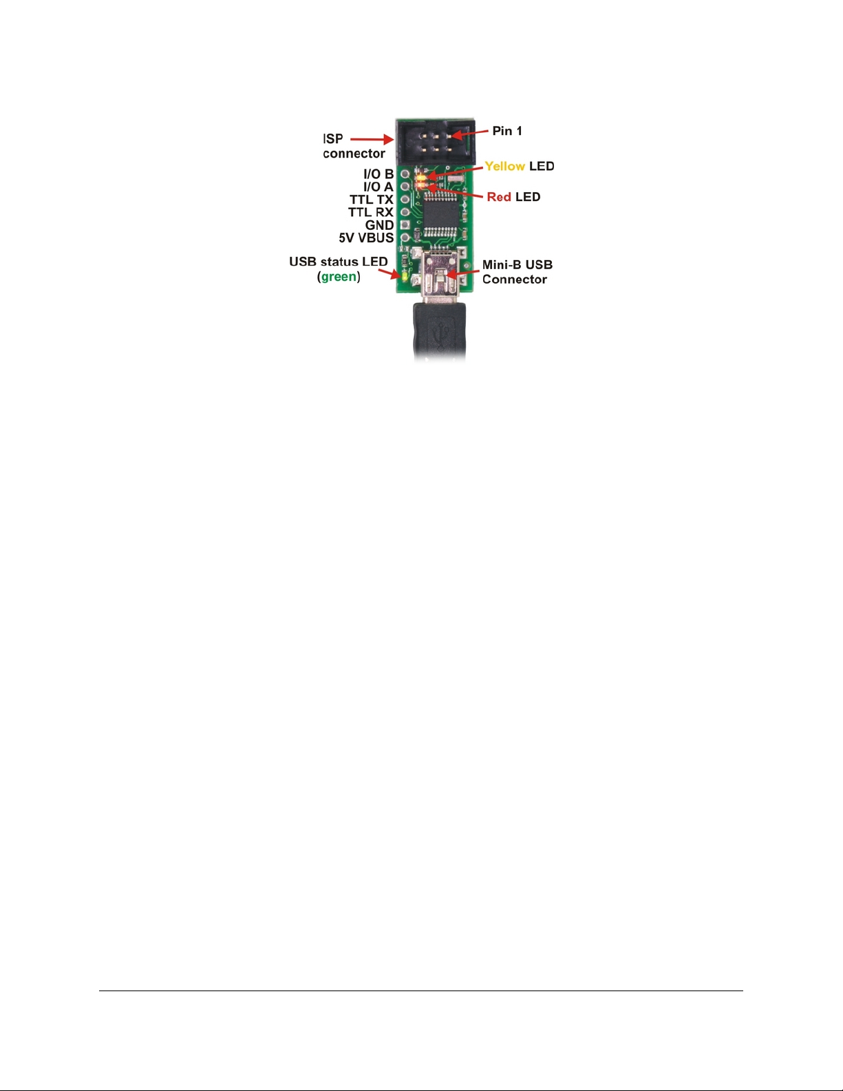
Pololu USB AVR programmer, labeled top view.
The Pololu USB AVR programmer connects to a computer’s USB port via an included USB
A to mini-B cable [http://www.pololu.com/catalog/product/130], and it connects to the target
device via an included 6-pin ISP programming cable [http://www.pololu.com/catalog/product/
972] (the older, 10-pin ISP connections are not directly supported, but it is easy to create or
purchase a 6-pin-to-10-pin ISP adapter).
The USB AVR programmer has three indicator LEDs:
• The green LED indicates the USB status of the device. When you connect the
programmer to the computer via the USB cable, the green LED will start blinking
slowly. The blinking continues until it receives a particular message from the computer
indicating that the drivers are installed correctly. After the programmer gets this
message, the green LED will be on, but it will icker briey when there is USB activity.
• The yellow LED indicates that the programmer is doing something. When it is
blinking, it means that the programmer has detected the target device (the voltage on
the target VDD line is high). When it is on solid, it means that the SLO-scope is enabled,
and lines Aand Bare used for the SLO-scope instead of the USB-to-TTL-serial adapter.
• The red LED indicates an error or warning. When it is blinking, it means that the
target device is not detected (the voltage on the target VDD line is low). When it is
on solid, it means that the last attempt at programming resulted in an error. You can
determine the source of the error by running the conguration utility (see Section 3.d).
The VBUS line provides direct access to the 5V VBUS line on the USB cable and can be
used to power additional devices. The line can provide up to 100 mA, so the current draw of
your programmer plus any additional devices should not exceed this amount. If you attempt
to draw more than this limit, your computer might disconnect the USB port temporarily or
take other actions to limit the use of USB power.
The GND line provides direct access to the grounded line on the USB cable (and ground on
the programmer).
The TX and RX lines are the TTL serial port for the USB-to-TTL-serial adapter. They are
labeled from the computer’s perspective: TX is an output that connects to your target’s
Pololu USB AVR Programmer User's Guide © 2001–2010 Pololu Corporation
1. Overview Page 3 of 36

serial receive pin and RX is an input that connects to your target’s serial transmit pin.
Section 5 describes how to use these lines to communicate with your devices from the
computer.
The Aand Blines can be used as serial control/handshaking lines for the USB-to-TTL-serial
adapter (see Section 5.a) or as analog voltage inputs for the SLO-scope (see Section 6).
Pololu USB AVR programmer bottom view with dimensions.
The USB AVR programmer has a standard 6-pin AVR ISP connector for programming
AVRs, and the pins are labeled on the silkscreen on the bottom side of the board. The pins
on the connector are:
1. MISO: The “Master Input, Slave Output” line for SPI communication with the target
AVR. The programmer is the master, so this line is an input.
2. VDD: An input line that the programmer uses to measure the voltage of the target
AVR. While programming the target device, the programmer uses this line to constantly
monitor the target VDD. If the voltage goes too low or varies too much, then the
programmer aborts programming in order to avoid damage to the target AVR. Section
3.d has more information about target VDD monitoring. The VDD line is not used to
power the programmer; the programmer is powered from the USB. This line cannot be
used to power the target device; the target device must be independently powered for
programming to work.
3. SCK: The clock line for SPI communication with the target AVR. The programmer is
the master, so this line is an output during programming.
4. MOSI: The “Master Output, Slave Input” line for SPI communication with the target
AVR. The programmer is the master, so this line is an output during programming.
5. RST: The target AVR’s reset line. This line is used as an output driven low during
programming to hold the AVR in reset.
6. GND: Ground. This line should be connected to the target device’s ground.
1.b. Supported Microcontrollers
The Pololu USB AVR programmer should work with all AVRs that can be programmed
by an AVR ISP, but it has not been tested on all devices (it has been tested with all
Orangutan robot controllers [http://www.pololu.com/catalog/category/8] and the 3pi
Robot [http://www.pololu.com/catalog/product/975]). The programmer features upgradable
rmware, allowing updates for future devices. It does not currently work with Atmel’s line
of XMega microcontrollers.
Pololu USB AVR Programmer User's Guide © 2001–2010 Pololu Corporation
1. Overview Page 4 of 36

The programmer is powered by the 5V USB power bus, and it is intended for programming
AVRs that are running at close to 5 V (note that the programmer does not deliver power to
the target device).
1.c. Supported Operating Systems
The Pololu USB AVR programmer has been tested under Microsoft Windows XP, Windows
Vista, Windows 7, and Linux. It is not compatible with any version of the Mac OS or
with older versions of Windows. Third-party programming software exists for all operating
systems.
The programer’s conguration utility works only in Windows, but this should not be a big
problem for Linux users because all the options that can be set in the conguration utility
are stored in persistent memory, so you would only have to use Windows when you want to
change those parameters, which should be rarely (if ever). The programmer does not require
the conguration to program AVRs or to use the TX and RX USB-to-TTL-serial adapter pins.
The SLO-scope application works only in Windows.
Pololu USB AVR Programmer User's Guide © 2001–2010 Pololu Corporation
1. Overview Page 5 of 36

2. Contacting Pololu
You can check the Pololu USB AVR programmer
page [http://www.pololu.com/catalog/product/1300] for additional
information. We would be delighted to hear from you about any of your
projects and about your experience with the Pololu USB AVR
Programmer. You can contact us [http://www.pololu.com/contact] directly
or post on our forum [http://forum.pololu.com/]. Tell us what we did well,
what we could improve, what you would like to see in the future, or
anything else you would like to say!
Pololu USB AVR Programmer User's Guide © 2001–2010 Pololu Corporation
2. Contacting Pololu Page 6 of 36

3. Getting Started in Windows
The Pololu USB AVR programmer works in Windows XP, Windows Vista, and Windows 7.
3.a. Installing Windows Drivers and the Conguration Utility
If you use Windows XP, you will need to have either
Service Pack 3 [http://www.microsoft.com/downloads/details.aspx?FamilyId=68C48DAD-
BC34-40BE-8D85-6BB4F56F5110] or Hotx KB918365 installed before installing the
drivers for the Pololu USB AVR programmer. Some users who installed the hotx
have reported problems using the programmer which were solved by upgrading to
Service Pack 3, so we recommend Service Pack 3 over the hotx.
Please note that these drivers will only work for the USB AVR programmer; if you have
Pololu’s original Orangutan USB programmer [http://www.pololu.com/catalog/product/740],
you will need to install the drivers specic to that device.
Before you connect your Pololu USB AVR programmer to a computer running Microsoft
Windows, you must install its drivers:
1. Download the pgm03a drivers, conguration, and SLO-scope
software [http://www.pololu.com/le/download/pgm03a_windows_091222.zip?le_id=0J198]
(4988k zip)
2. Extract the les in pgm03a_windows.zip to a temporary directory by right-clicking
on the ZIP le and selecting “Extract All…”
3. Open the temporary directory, right click on pgm03a.inf and select “Install”. (Do not
try to install the other INF le in the directory.)
4. After selecting “Install”, Windows will warn you that the driver has not been tested
by Microsoft and recommend that you stop the installation. Click “Continue Anyway”
(Windows XP) or “Install this driver software anyway” (Windows Vista).
Pololu USB AVR Programmer User's Guide © 2001–2010 Pololu Corporation
3. Getting Started in Windows Page 7 of 36

Windows Vista and Windows 7 users: After the INF le is installed, your computer
should automatically install the necessary drivers when you connect a Pololu USB AVR
programmer, in which case no further action from you is required.
Windows XP users: After the INF le is installed, follow steps 5-9 for each new Pololu USB
AVR programmer you connect to your computer.
5. Connect the USB AVR programmer to your computer’s USB port. The programmer
is actually three devices in one so your XP computer will detect all three of those
new devices and display the “Found New Hardware Wizard” three times. Each
time the “Found New Hardware Wizard” pops up, follow steps 6-9.
6. When the “Found New Hardware Wizard” is displayed, select “No, not this time” and
click “Next”.
7. On the second screen of the “Found New Hardware Wizard”, select “Install the
software automatically” and click “Next”.
Pololu USB AVR Programmer User's Guide © 2001–2010 Pololu Corporation
3. Getting Started in Windows Page 8 of 36

8. Windows XP will warn you again that the driver has not been tested by Microsoft and
recommend that you stop the installation. Click “Continue Anyway”.
9. When you have nished the “Found New Hardware Wizard”, click “Finish”. After
that, another wizard will pop up. You will see a total of three wizards when plugging in
the programmer. Follow steps 6-9 for each wizard.
If you use Windows XP and experience problems installing the serial port drivers, the
cause of your problems might be a bug in older versions of Microsoft’s usb-to-serial driver
Pololu USB AVR Programmer User's Guide © 2001–2010 Pololu Corporation
3. Getting Started in Windows Page 9 of 36

usbser.sys. Versions of this driver prior to version 5.1.2600.2930 will not work with the
USB AVR programmer. You can check what version of this driver you have by looking in
the “Details” tab of the “Properties” window for C:\Windows\System32\drivers\usbser.sys.
To get the xed version of the driver, you will need to either install
Service Pack 3 [http://www.microsoft.com/downloads/details.aspx?FamilyId=68C48DAD-
BC34-40BE-8D85-6BB4F56F5110] or Hotx KB918365. Some users who installed the hotx
have reported problems using the programmer which were solved by upgrading to Service
Pack 3, so we recommend Service Pack 3 over the hotx.
After installing the drivers, if you go to your computer’s Device Manager and expand the
“Ports (COM & LPT)” list, you should see two COM ports: “Pololu USB AVR Programmer
Programming Port” and “Pololu USB AVR Programmer TTL Serial Port”. In parentheses after
these names, you will see the name of the port (e.g. “COM3” or “COM4”). If you expand the
“Pololu USB Devices” list you should see an entry for the Pololu USB AVR programmer.
Windows XP device manager showing the Pololu USB AVR Programmer
Windows Vista device manager showing the Pololu USB AVR Programmer
Some software will not allow connection to higher COM port numbers. If you need to
change the COM port number assigned to your USB device, you can do so using the Device
Manager. Bring up the properties dialog for the COM port and click the “Advanced…” button
in the “Port Settings” tab. From this dialog you can change the COM port assigned do your
device.
Once your have successfully installed the device drivers, you can run the conguration
utility that came in the ZIP le, pgm03a_cong.exe. This is a stand-alone Windows
application that allows you to change many of the settings of your programmer. Please see
Section 3.d for more information.
Pololu USB AVR Programmer User's Guide © 2001–2010 Pololu Corporation
3. Getting Started in Windows Page 10 of 36

This software package also contains the installation les for the Pololu SLO-scope
application for Windows. Please see Section 6 for installation and usage instructions.
3.b. Programming AVRs Using AVR Studio
After you’ve installed the necessary drivers, the next step is to download and install a
compiler. WinAVR [http://winavr.sourceforge.net/] is an open source suite of software
development tools for the Atmel AVR series of microcontrollers. It includes the GNU GCC
compiler for C and C++. Please follow the installation instructions they provide.
WinAVR alone will give you all the tools you need to start programming AVRs with the
USB AVR programmer, but Atmel oers AVR Studio [http://www.atmel.com/avrstudio/], a free
integrated development environment (IDE) designed to work with the WinAVR GCC C/C++
compiler. AVR Studio includes a simulator and other useful tools, and supports the AVR
ISP protocol used by the Orangutan USB programmer. Please follow Atmel’s installation
instructions. Note that newer versions of AVR Studio might not work with older versions of
WinAVR, so we recommend you upgrade to the newest version WinAVR every time you get a
new version of AVR Studio.
The following tutorial covers the steps needed to program AVRs using AVR Studio and
a Pololu USB AVR programmer. Specically, we will write a simple program to blink
an LED connected to pin PD1 of an AVR. On any of the Orangutan robot
controllers [http://www.pololu.com/catalog/category/8] and the 3pi
Robot [http://www.pololu.com/catalog/product/975], this program will blink the red user LED. If
you want to program an AVR that does not have an LED connected to pin PD1, the LED-
blinker code in this tutorial will have no visible eect.
If you have an Orangutan or 3pi and want to jump straight in to using your USB AVR
programmer, you can skip steps 1-3 by downloading the AVR Studio project these steps
would create. Determine the microcontroller on your device, download the corresponding
le below, extract all the les to a directory, open the AVR Studio project le (BlinkLED.aps),
and proceed to step 4.
• mega48: BlinkLED_m48.zip [http://www.pololu.com/le/download/
BlinkLED_m48.zip?le_id=0J188] (9k zip)
• mega168: BlinkLED_m168.zip [http://www.pololu.com/le/download/
BlinkLED_m168.zip?le_id=0J189] (9k zip)
• mega328: BlinkLED_m328.zip [http://www.pololu.com/le/download/
BlinkLED_m328.zip?le_id=0J190] (9k zip)
1.
Open AVR Studio and click New Project. Select AVR GCC for the project type. Enter
the project name and initial le name. In the screenshot below, we named our project
“BlinkLED” and elected to have a folder called “C:\BlinkLED” created containing the
blank le “BlinkLED.c”. Click Next >>. DO NOT click “Finish” yet. If you do accidentally
click “Finish”, you will not be able to perform step 2 and will instead have to set the
device by going to the “Project” menu and selecting “Conguration Options”.
Pololu USB AVR Programmer User's Guide © 2001–2010 Pololu Corporation
3. Getting Started in Windows Page 11 of 36

Creating a new AVR Studio project, step 1
2.
Select AVR Simulator as the debug platform and then select the appropriate device
for your target AVR. For an Orangutan or 3pi Robot, this will either be ATmega48,
ATmega168, or ATmega328P depending on which chip your Orangutan or 3pi Robot
has. Click Finish.
Creating a new AVR Studio project, step 2
3.
Write your program in BlinkLED.c as seen in the screen shot below and click the Build
button on the toolbar (or press F7).
Pololu USB AVR Programmer User's Guide © 2001–2010 Pololu Corporation
3. Getting Started in Windows Page 12 of 36

Building a project with AVR Studio
Note: You will probably want to customize this program slightly if the clock
frequency of your AVR is not 20 MHz. F_CPU should be dened as the clock
frequency of your AVR in units of Hz. If you do not make this change, the timing
of delayms() will be o, but the LED will still blink.
4.
Make sure your USB AVR programmer is connected to your computer via its USB A to
mini-B cable and then click the Display the ‘Connect’ Dialog button on the toolbar.
You can also accomplish this by going to the “Tools” menu and selecting Program AVR
> Connect….
Connecting to the programmer with AVR Studio
5.
This will bring up a programmer selection dialog. Select AVRISP as the platform. The
USB AVR programmer uses AVR ISP version 2, which is written as AVRISPv2. Please
note that this is not the same as AVR ISP mkII. Select the port name of your programmer
if you know what it is, or select Auto and AVR Studio will try all the ports until it detects
the programmer. You can determine your programmer’s port name by looking in the
“Ports (COM & LPT)” list of your Device Manager for “Pololu USB AVR Programmer
Programming Port”. Click “Connect…” to bring up the ISP window.
Pololu USB AVR Programmer User's Guide © 2001–2010 Pololu Corporation
3. Getting Started in Windows Page 13 of 36

AVR Studio’s programmer-selection dialog
If the ISP window does not appear when you click “Connect…”, your computer cannot
detect the programmer. Please see Troubleshooting (Section 7) for help identifying and
xing the problem.
If AVR Studio brings up a dialog asking if you want to upgrade (or downgrade) your
programmer’s rmware, click Cancel to ignore the message and use your programmer.
To prevent this dialog from appearing in the future, use the Conguration Utility
(Section 3.d) to change the programmer’s hardware and software version numbers.
6.
Select the Main tab. In the dropdown box that lists AVR models, select the same device
that you selected when you created the project. For an Orangutan or 3pi Robot, this will
either be ATmega48,ATmega168, or ATmega328P.
Selecting the device for ISP programming in AVR Studio
7.
If you have not done so already, connect the programmer to the target device using the
6-pin ISP cable. Make sure the cable is oriented so that pin 1 on the connector lines
up with pin 1 on your target device! You can test the connection by going to the Main
tab and clicking the Read Signature button. This sends a command to the target AVR
asking for its device signature. If everything works correctly, you should see “Signature
matches selected device”. If the signature does not match the selected device, you
probably have the wrong device selected (or possibly your target device is turned o).
If reading the signature fails entirely, please see Troubleshooting (Section 7) for help
getting your connection working.
Pololu USB AVR Programmer User's Guide © 2001–2010 Pololu Corporation
3. Getting Started in Windows Page 14 of 36

Reading the device signature in AVR Studio’s Main ISP tab
8.
Now it is time to program your target device. Select the Program tab. Your Input HEX
File in the Flash section needs to be the hex le that was generated when you built
your program. You can browse for this using the "..." button to the right of the input le
text box. If you navigate to your project’s folder, you should nd it as “default\<project
name>.hex”. Click the Program button (make sure you click the one in the Flash
section, not one in the “EEPROM” or “ELF Production File Format” sections!).
AVR Studio’s Program ISP tab
As your USB AVR programmer programs the AVR, you should see all three LEDs icker
and you should see the following text appear at the bottom of the window:
Reading FLASH input file.. OK
Setting mode and device parameters.. OK!
Entering programming mode.. OK!
Erasing device.. OK!
Pololu USB AVR Programmer User's Guide © 2001–2010 Pololu Corporation
3. Getting Started in Windows Page 15 of 36

Programming FLASH .. OK!
Reading FLASH .. OK!
FLASH contents is equal to file.. OK
Leaving programming mode.. OK!
If there were no problems, the LED connected to PD1 of your AVR should now be
ashing! Note that if you are trying this on a 3pi robot and you have not yet soldered
in the optional through-hole LEDs, the ashing LED will be on the bottom of the robot.
If there was a problem, please see Troubleshooting (Section 7) for help identifying and
xing it.
3.b.1. Using Advanced Features of AVR Studio
This section provides a brief overview of the programming features of AVR Studio that were
not covered in Section 3.b. You will not typically need to use of these advanced features,
but it is good to know about them for the rare occasions when you will need them. Please
see the Atmel’s AVR Studio documentation for more detailed descriptions of these features.
ISP Frequency
In the ISP window, under the Main tab, the Programming Mode and Target Settings
section lets you set the frequency of the clock used when programming the target device.
The higher the ISP frequency, the faster the target AVR will be programmed, but this
frequency must be less than a quarter of the target AVR’s clock frequency. Click Read to
read the frequency from the programmer and click Write to write the selected frequency
to the programmer. It is important to note that the frequencies in the ISP Freq list are not
correct when you are using the Pololu USB AVR programmer. See Section 3.d for a list of
the actual frequencies and more information about selecting the ISP frequency.
AVR Studio’s interface for setting the ISP frequency.
Pololu USB AVR Programmer User's Guide © 2001–2010 Pololu Corporation
3. Getting Started in Windows Page 16 of 36

Fuses (proceed with caution!)
Clicking on the Fuses tab automatically causes the programmer to read the fuse settings of
the target AVR. If the programmer is not connected to the target AVR when you select this
tab, AVR Studio displays an error message. Fuses allow you to congure certain persistent,
fundamental aspects of your AVR such as boot ash size, brown-out detection level, and the
clock o of which it should run (e.g. external crystal or internal oscillator). To learn more
about the fuses and what they do, see the datasheet for your specic AVR.
Warning: You can permanently disable your AVR by setting the fuses
incorrectly. Only advanced users who know precisely what they are doing
should change the fuse settings!
Lock Bits
Clicking on the Lock Bits tab automatically causes the programmer to read the lock bits
of the target AVR. If the programmer is not connected to the target AVR when you select
this tab, AVR Studio displays an error message. Lock bits allow you to secure your AVR by
preventing further ash writing or reading. The lock bits can be reset to a fully unlocked
state by performing a chip erase (i.e. by clicking the Erase Device button in the Main tab).
Lock bits are usually only important if you wish to release a product to other people without
giving them access to the program it is running, or if you wish to make it slightly more
diicult to overwrite a programmed chip.
3.c. Programming AVRs Using AVRDUDE
It is possible to program AVRs in Windows using AVRDUDE [http://www.bsdhome.com/
avrdude/]. AVRDUDE is free and included in the WinAVR [http://winavr.sourceforge.net/]
package. To program a hex le on to your AVR, you would type something similar to the
following into a command prompt:
cd C:\BlinkLED\default
avrdude -p m168 -P COM2 -c avrispv2 -e -U flash:w:BlinkLED.hex
• The argument following the -p is the part number of the AVR. For an Orangutan or
3pi Robot, the part number should be m328p,m168, or m48.
• The argument following the -P is the port name. You can determine your
programmer’s port name by looking in the “Ports (COM & LPT)” list of your Device
Manager for “Pololu USB AVR Programmer Programming Port”.
• The argument following the -c is the programmer protocol and should be avrispv2.
• The -e option requests an initial chip erase.
• The -U option is used for writing, reading, or verifying ash, EEPROM, fuses, or lock
bits. In this example we are using -U to write BlinkLED.hex to ash.
Please see the AVRDUDE documentation [http://www.nongnu.org/avrdude/user-manual/
avrdude.html] for more detailed information.
3.d. Conguring the Programmer
The Pololu USB AVR programmer can be congured using the Pololu USB AVR Programmer
Conguration Utility for Windows. The utility comes with the Windows drivers (Section
3.a) and can be run by double clicking on the executable pgm03a_cong.exe. This section
describes all the available settings and what they do.
Pololu USB AVR Programmer User's Guide © 2001–2010 Pololu Corporation
3. Getting Started in Windows Page 17 of 36

Pololu USB AVR programmer conguration utility for Windows.
Target VDD Monitor
The USB AVR programmer monitors the voltage of the target AVR while it is being
programmed to ensure that ISP commands are only sent when the AVR’s VDD is at a safe
level, since attempting to program an underpowered AVR can permanently disable it. There
are two parameters that control this feature:
•Minimum Allowed: This parameter determines the lowest level (in millivolts) that
the target AVR’s VDD is allowed to go. If the target AVR’s VDD drops below this level,
the programmer immediately aborts programming and turns on the red programming
LED. Lowering this value will allow programming of AVRs at lower voltages, but will
make it more likely that the programmer will send ISP commands to the AVR while the
AVR is running at an unsafe voltage. The default value is 4384 mV.
•Maximum Range Allowed: This parameter determines how much the target AVR’s
VDD measurements are allowed to vary (in millivolts). When the programmer recieves
an ISP programming request, it starts keeping track of the maximum and minimum
measurements of the AVR’s VDD. If the dierence between the maximum and minimum
exceeds the allowed maximum range, the programmer immediately aborts programming
and turns on the red programming LED. Increasing this value will allow programming
of AVRs under less stable power conditions, but will make it more likely that the
programmer will send ISP commands to the AVR while the AVR is running at an unsafe
voltage. The default value is 512 mV.
Measurements From Last Programming
This section displays the minimum and range of the target VDD measurements from the last
time the programmer was in programming mode or tried to enter programming mode. This
can help determine whether programming problems are due to the target’s power supply.
Error From Last Programming
When an error or unexpected condition causes the programmer to leave programming mode,
or fail to enter programming mode, then the programmer turns on the red LED and records
Pololu USB AVR Programmer User's Guide © 2001–2010 Pololu Corporation
3. Getting Started in Windows Page 18 of 36

the error code. A description of the error can be found here. See Troubleshooting (Section
7) for details on specic error messages.
ISP Frequency
The higher the ISP frequency, the faster you can program the target AVR, but the ISP
frequency must be less than a quarter of the target AVR’s clock frequency.
The ISP frequency can be set in AVR Studio (see Section 3.b.1) as well as in the
Conguration Utility, but the frequencies listed in the AVR Studio user interface do not
match the actual frequencies used by the Pololu USB AVR programmer.
Frequency Listed
in AVR Studio Actual Frequency Allowed Target
Frequency
1.845 MHz 2000 kHz > 8 MHz
460.8 kHz 1500 kHz > 6 MHz
115.2 kHz 750 kHz > 3 MHz
57.6 kHz 200 kHz > 800 kHz
4.00 kHz 4.0 kHz > 16 kHz
1.21 kHz* 1.5 kHz* > 6 kHz
*This ISP frequency is so low that AVR Studio times out while attempting to program ash
or EEPROM pages, but it can be used to program fuses and lock bits on AVRs running at
frequencies as low as 6 kHz.
An AVR running at 20 MHz or higher (e.g. the Orangutan SV-xx8, Orangutan LV-168, Baby
Orangutan, and 3pi robot) can be programmed at 2000 kHz (1.845 MHz in AVR Studio),
which is the fastest setting.
An AVR running at 8 MHz or higher (e.g. the original Orangutan) can be programmed at
1500 kHz (460.8 kHz in AVR Studio).
An AVR running at 1 MHz, such as one clocked o of the internal RC oscillator with
the divide-by-8 fuse bit programmed, can be programmed at an ISP frequency as high
as 200 kHz (57.6 kHz in AVR Studio). This is the USB AVR programmer’s default ISP
frequency.
The two lowest frequencies support AVRs with a clock frequency under 1 MHz. The 1.5 kHz
setting is too slow to actually program the ash or EEPROM on your target device using AVR
Studio (it will timeout while attempting to program the ash/EEPROM pages), but it will still
let you set the fuses. Be aware that if you attempt to program ash or EEPROM at 4.0 kHz,
it might take ve minutes or longer to program a 16KB of ash, so we only recommend this
ISP frequency for putting small programs on very low-frequency AVRs.
Serial Number
This is a unique identier assigned to this programmer by Pololu. This number can not be
changed.
Pololu USB AVR Programmer User's Guide © 2001–2010 Pololu Corporation
3. Getting Started in Windows Page 19 of 36

TTL Serial Port
This section is used to identify pins A and B with serial handshaking lines so that they can
be used as general purpose user I/O lines. See Section 5.a.
AVR ISP Emulation
This section is used to change the hardware and software version numbers of the
programmer. These numbers are read by AVR Studio when it connects to the programmer
and are expressed in hex. If these numbers do not match the numbers that AVR Studio
expects, then it brings up a dialog asking if you want to upgrade (or downgrade) your
programmer’s rmware; the Pololu AVR USB programmer does not support this method
of rmware upgrading, so this dialog is nothing more than a nuisance to those not using
an Atmel programmer. You should click Cancel to ignore the message and proceed to the
AVRISP programming dialog. To prevent this rmware-upgrade dialog from appearing in the
future, set the numbers here to the numbers that AVR Studio says it expects.
Pololu USB AVR Programmer User's Guide © 2001–2010 Pololu Corporation
3. Getting Started in Windows Page 20 of 36
Table of contents
Other Pololu Motherboard manuals
Popular Motherboard manuals by other brands

International Rectifier
International Rectifier IR3847 user guide

Freescale Semiconductor
Freescale Semiconductor LS1043ARDB quick start

Texas Instruments
Texas Instruments ADS131E08 user guide

Honeywell
Honeywell DCP551 Mark ll user manual

Intersil
Intersil ISL8216MEVAL1Z user guide

Supermicro
Supermicro X12SDV-4C-SPT4F user manual