Poly Pong CRUISE SHIP ALL-WEATHER User manual

ASSEMBLY
MANUAL
CRUISE SHIP
ALL-WEATHER
2-5-2020

UNPACKING INSTRUCTIONS
You should have received two cartons. The main shipping pallet is 53 inches by 52 inches
and 48 inches tall. Also, you should have an eight inch diameter cylinder that is 84 inches
long. Inspect your shipping containers and look for any physical damage. If you find any,
photograph it and report it to the shipping company. Remove the top and sides of your
pallet. Look for any internal damage. Report this if you find any.
Unpack al of the contents of the pallet and cylinder. You should find the parts as shown in
Figure 1. Make sure that you can identify all of the components. Save the packing boxes.
1. Bumpers 5. Pipe braces
2. Table tops 6. I beams
3. Table joiners 7. Box of accessories,
fasteners
4. Legs 8. Center post
1.
2. 3. 4.
5. 6. 7. 8.
Fig. 1
ASSEMBLY
Carefully lay out The four Styrofoam sheets that the table tops were packed in in the form
of a 2 by 2 square with the pieces spaced about four inches apart. These provide a clean
surface to protect the table tops during assembly. If these were damaged, you can use the
card board boxes instead. Be sure to remove all metal staples. Now carefully place the
four table tops upside down on the Styrofoam sheets and in the colors shown if Fig. 2.
PAGE 1

Fig. 2 6 in.
6 in.
Locate one of the table joiners and insert it as shown if Fig. 3. Push the two table tops
together so that they touch the sides of the table joiner. Fasten the joiner to the table tops
using four 8 mm x 30 mm screws and large washers shown also in Fig, 3. LEAVE
THESE SCREWS SLIGHTLY LOOSE. Repeat with the remaining Table joiners so that
all four table tops are connected, Fig. 4. All the screws are still loose.
Fig. 3
Fig. 4
PAGE 2

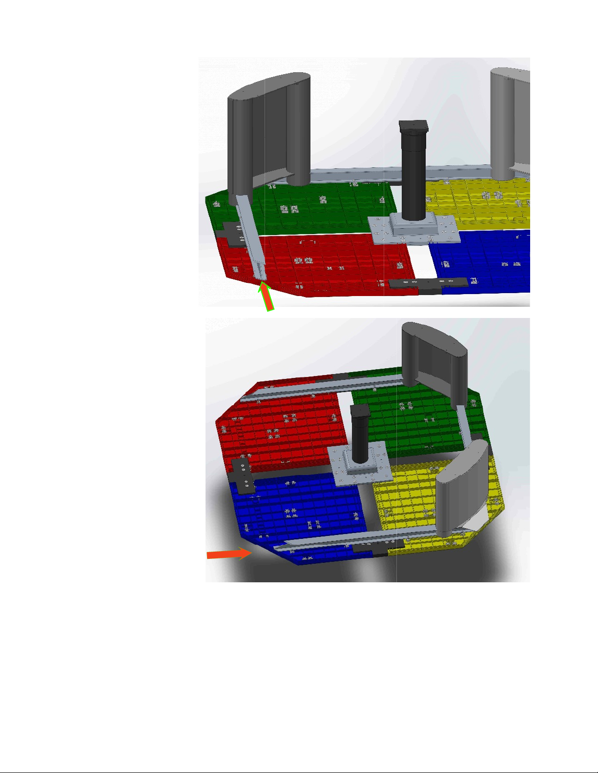
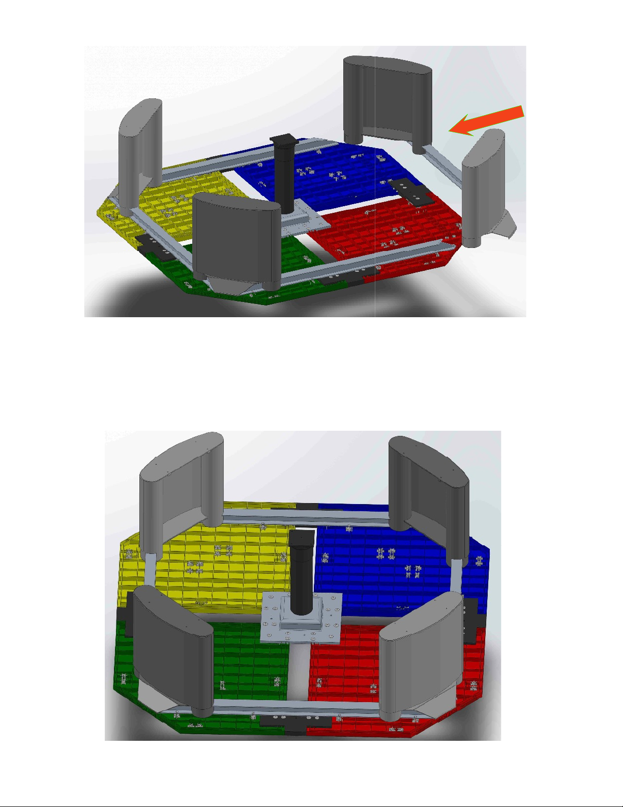
Now locate the center post. This will be
placed in the center of the four tables with
the large end down. It should fit snugly
between the table tops. Fig. 5.
Four 8 mm x 30 mm screws with large
washers should be screwed into the molded
nuts that are in the corners of each of the
four table tops. THESE SHOULD BE
ONLY TIGHTENED LOOSELY. Fig. 6.
You may now tighten all loose screws
in the table joiners and the four screws
in the center post. Now add sixteen
more 8 mm x 30 mm screws and large
washers to the remaining holes in the
center post, using four per table top.
Cinch these screws up tightly. Your
assembly should now look like Fig. 7.
Fig. 6
Fig. 5
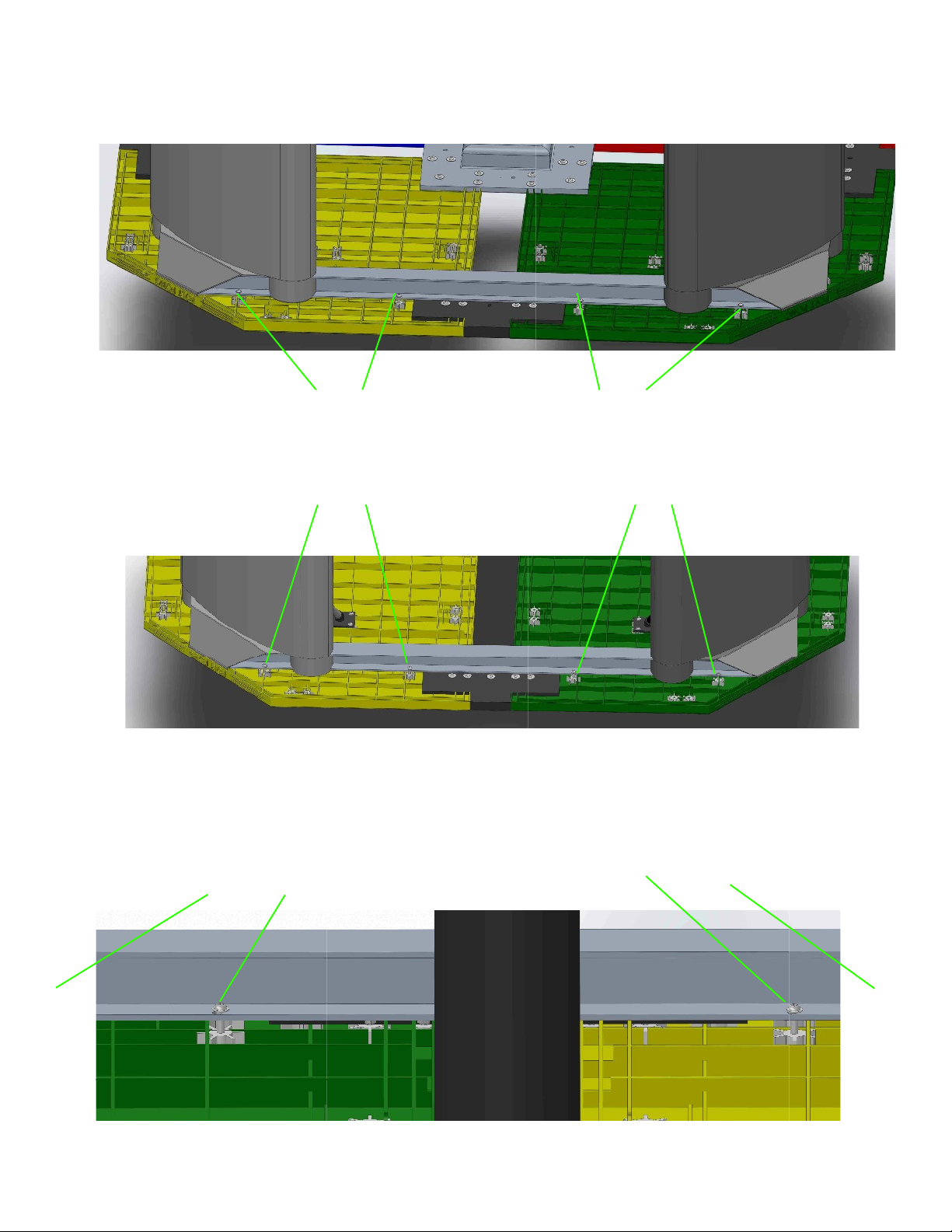
NOW CHECK AGAIN TO MAKE SURE
THAT THE DISTANCE BETWEEN EACH
TABLE TOP AND ITS ADJOINING TWO
TABLE TOPS IS EXACTLY 6 INCHES.
ALSO SIGHT ALONG THE OUTER
EDGES OF THE FOUR TABLE TOPS
AND INSURE THAT THEY ARE IN
PERFECT ALIGNMENT.
Fig. 7
PAGE 3
NOTE: Use both large
and small washers as
shown in this picture
for the 20 bolts in this
page.

BEAM AND LEG ASSEMBLY
Locate one I beam and one leg
assembly and position the beam
so that the longest side is down
and that the beveled end tapers
toward you. Carefully, slide the
beam into the ”I” slot on the end
of the leg assembly. Fig. 8.
It should pass through the leg
cylinder and protrude out the back
side. Keep advancing it through
until it makes contact with the
beam cover. Fig. 9. You may
need to use a soft mallet or a
hammer against a board to help
move the beams into the legs.
Fig. 8
Fig. 9
PAGE 4

Bring a second leg assembly into
position shown Fig. 10.
Carefully slide this leg onto the “I”
beam as you did before. It should
protrude through the leg assembly
and be advanced until it touches
the beam cover. Fig. 11.
Fig. 10
Fig. 11
This beam-leg assembly is then placed onto the four table tops assembly. This is shown in Fig. 12 as
being about 15 inches above the table top assembly.
Fig. 12
PAGE 5

Lower the beam-leg
assembly onto the table
tops assembly and
position it so that the
beam covers on each end
fit into the slots just inside
the front diagonal lip of
the table edge just above
the inverted POLY PONG
logo and centered on the
diagonal table edge. This
should be the same for
both sides Fig. 13 & 14.
Fig. 13
Fig. 14
PAGE 6

Look carefully and you will notice four bolt holes on the lower outer lip of the “I” beam.
(There are four on the inside as well.) Carefully re-position the beam slightly so that
these holes align up with four imbedded nuts it the table tops. Using 8 mm by 20 mm
screws and SMALL washers, attach the beam to the table tops. LEAVE THESE
SCREWS LOOSE. Fig 15.
Fig. 14
Fig. 15
Now do the same for the four holes on the inside of the beam. Use 8 mm x 20 mm
screws and small washers. The beam may need to be re-positioned slightly. Fig. 16.
Two of these screw holes are on the far side of the leg assemblies under the beam
covers. LEAVE THESE SCREWS LOOSE. Fig. 16.
Fig, 16
PAGE 7

Insert another “I” beam
into the remaining “I”
slot in the leg on the
green table top. Fig. 17.
Position it as you did
before. Add another “I”
beam. This one goes into
the leg on the yellow
table top. Fig. 18.
Fig, 17
Fig. 18
Assemble another leg-”I” beam assembly with your remaining two legs and the remaining
“I” beam as you did in Figures 8 through 11. This one will be positioned to slide onto the
two beams extending from the green and yellow table tops. This will require the help of
two people. Fig. 19.
PAGE 8

Fig. 19
Carefully re-adjust each beam so that the bolt holes all align. Check each beam cover
to insure that they are in the slot just inside the front angle table top. Fig. 14. Now
add eight 8 mm x 20 mm screws and small washers for each beam. LEAVE
THESE SCREWS LOOSE. Fig. 20.
Page 9
Fig. 20

Page 10
ADDING THE PIPE BRACES
There are eight pipe braces to be added, two per table top. The pipe braces swivel on
their base. Position the pipe brace as shown in Fig. 21. The flange should be aligned
parallel with the nut holes as shown but slightly away from the leg pipe. The other
end should swivel around to be made to align up with the hole drilled in the leg pipe.
Fig. 21. There are left pipe braces and right pipe braces, Select the one that fit squarely into the leg.
It should make a press fit into the hole
when the flange at the bottom is moved
to align with the four nuts in the table
top. When you are sure that everything
fits, pull the pipe brace back out from the
leg pipe, apply some PVC cement to the
end of the brace and some to the edge of
the hole. Quickly re-insert the brace end
into the hole and bolt the bottom flange
in place using four 8 mm x 20 mm
screws and small washers. The cement
sets quickly. You only have about 10-15
seconds to get it in place. Fig. 22. If it is
difficult to get it to fit, have a helper pull
out on the leg foot to extend it slightly.
It should then fit snuggly when your
helper relaxes his pull. See the arrow.
Fig. 21
Fig. 22.\

Repeat for the second pipe brace on the
yellow table top. If it is difficult to get
the pipe end into the hole, have the
helper pull out on the table leg making
it bow out slightly. Then you can get
the end to go into the hole as desired.
Fig, 23. Note the arrow. Remove it,
add some PVC cement to the brace end
and the hole edge as you did before.
When you have successfully mounted two pipe braces, proceed to the other three
leg assemblies. When completed, your table should resemble Fig. 24. Now Make
sure that everything is in place, then tighten all of the screws.
Fig. 23
Fig. 24
THIS COMPLETES THE ASSEMBLY OF THE TABLE BOTTOM SIDE.
Let the glue dry at least one hour.
Page 11

This step is the hard part. Use at least four helpers. You must lift up the table
and carefully turn it right-side-up without putting pressure on the legs against the
floor. You want to flip it over in the air and then allow the feet to touch the floor.
Once this is done, you can then carry it into the desired location and position.
Fig. 25.
ATTACHING THE BUMPERS
Notice the two threaded inserts on
the bottom side of the bumper.
Fig, 26. Insert a 60 mm screw into
each thread insert and bend the nut
placement if necessary to make
them perpendicular then remove
the screw. These are made to align
up with the two holes, one in the
table joiner and the other in the
center post top. Fig. 27.
Take the bumper and place it into
the slot for the bottom protrusion
with the pointed end towards the
table center. It should settle into
the gap between the two table
tops. Fig. 28 & 29.
Page 12
Fig. 25
Fig. 26
Fig. 27

From the underside of the table,
look through the two holes, one in
the center post and the other in the
table joiner. Carefully slide the
bumper until you can see the nut
inserts. Fig. 30 shown in
transparent mode.
Using an 8 mm x 60 mm screw
with a LARGE washer, put a
screw up into the hole in the center
post, then on into the bumper
insert. Repeat with a similar screw
through the table joiner into the
bumper insert. Fig. 31 & 32. Do
not cinch them up yet.
Repeat for the other three
bumpers.
Fig. 28
Fig. 29
Fig. 31 Fig. 32
Page 13
Fig. 30

Looking from the top,
gently slide each bumper
so that all the points
meet in the center and
the angled edges meet
smoothly. Fig. 33.
Once this is done, return
to the underside and
cinch up all eight of the
8 mm x 60 mm screws.
Fig. 33
All that remains is to secure
your table to the floor. This
is done by putting one or two
fasteners through each
corner leg. Use large
washers with your bolts.
Anchor the center post as
well. Only the large washers
are supplied. Choose
mounting hardware that
conforms to your surface.
YOUR TABLE IS NOW
COMPLETE! Mounting hardware
Page 14
Fig. 34
You will find four colorful paddles and some balls to test out your installation.

TABLE MAINTENANCE
Hand smudges, paddle scars, etc. can be wiped off using a mild soap, warm water and a
soft rag. The plastic surfaces on the legs and bumpers can be similarly cleaned. In
time, the bumpers will get hard and crack due to the ultra-violet sun rays. They can be
periodically replaced by placing an order to Poly Pong, Inc. This is true for any part of
your table.
The table colors are also susceptible to the ultra-violet rays. The paint contains UV
inhibitors but it eventually will fade. Yellow is the most susceptible to attack. Any of
the colors can be recoated. Use Valspar LIC43 low gloss Polyurethane Enamel of the
desired color. Mix with LK40 polyurethane LIC activator, four parts LIC to one part
LK40. One quart will easily coat a table top. The yellow top is John Deere yellow.
Black surfaces are coated with Sherman Williams paint Hi-Solids Polyurathane B65
TWJ 304 with B60V20 activator.
The process is:
1. Remove the bumpers by removing the two screws that hold each to the table..
2. Clean the surface thoroughly with a mild soap. Rinse thoroughly.
3. When dry, sand lightly with 320 grit sand paper.
4. Mask off the table joiners and any other nearby surfaces
5. Apply by roller or spray a good quality acrylic paint, one that has a good UV
inhibitor rating and requires a hardener to be stirred into the mix.
6. When it is thoroughly dry, remove the masking tape and replace the bumpers.
Page 15
POLY PONG, INC
412 South 100 East
Salem, Utah 84653
www,polypong.com
1-801-473-1321
Table of contents