Polycote ECS DO 335 Pfeil Arrow Supplement

Model airplanes, model engines, model engine fuel, propellers
and related accessories, tools and equipment can be haz-
ardous if improperly used. Be cautious and follow all safety
recommendations when using your VMAR model airplane.
Keep hands, tools, clothing and all foreign objects well clear of
engines when they are operating. Take particular care to
safeguard and protect your eyes and fingers and the eyes and
fingers of other persons who may be nearby. Use only a good
quality propeller that has no cracks or flaws. Stay clear of the
propeller and stay clear of the plane of rotation defined by the
propeller. The Manufacturer, Distributor, Retailer and/or other
suppliers of this product expressly disclaim any warranties or
representations, either expressed or implied, including but not
limited to implied warranties of fitness for the purposes of
achieving and sustaining remotely controlled flight. In no event
will the Manufacturer, Distributor, Retailer and/or other
suppliers of this product have any obligation arising from
contract or tort, or for loss of revenue or profit, or for indirect,
special, incidental, consequential or other damages arising
from the use of this product. In purchasing and/or using this
product, the user accepts all responsibility for its use and
accepts all liability associated with such use.
A Remote Control Model Aircraft is not a toy. It is a flying
model that functions much like a full size airplane. If you
do not assemble and operate this product properly you
can cause injury to yourself and others and damage
property. DO NOT FLY this model if you are not qualified.
You are entirely responsible for the mechanical,
aeronautical and electrical integrity of this model and it's
structure, control surfaces, hinges, linkages, covering,
engine, radio, wiring, battery and all other components.
Check all components before and after each flight.
Don't fly until it's right!
The Graphics and Detailing are inside the POLYCOTE ECS!
Proceeding with assembly and use of this product indicates
Agreement With & Acceptance of the following Liability Disclaimer.
CAUTION
ASSEMBLY & OPERATIONS MANUAL
Please review this manual thoroughly before assembling or operating this model.
16
VMAR, POLYCOTE and VMAX are Trademarks of VMAR Manufacturing Inc. and appointed VMAR agents worldwide.
Copyright VMAR Manufacturing Inc - 20070501
DO 335 Pfeil
Arrow
ARROW TIGER
DEHAVILAND DHC-6 TWIN OTTER
Order Item #VMA-A460B
Order Item #VMA-A340R Order Item #VMA-A340Y
Order Item #VMA-E340V
Order Item #VMA-E340Y
Order Item #VMA-T210W
Order Item #VMA-E340R

2
Parts needed
- Right and left wing panels
- Roll of wing joiner tape
- Wing joiner (also called dihedral brace)
- Two short dowel guides
.
Tools and adhesives needed
- 30 minute epoxy
- Epoxy brush or stir sticks
- Disposable mixing dish for the epoxy
- Sandpaper (coarse 240 grit recommended)
- Low tack masking tape
- Pencil
- Knife
- Ruler
- Paper towels
WING ASSEMBLY - JOINING THE WING HALVES
STAGE 1
STEP 1.1 Locate the wing joiner (also called the dihedral
brace). Using a ruler, mark a center line on the wing joiner as
illustrated in 1A. Also mark a center line on each of the dowel
guides..
Step 1.2 Trial fit the wing joiner into the wing panels. It
should insert smoothly up to the center line as illustrated in
1B. Now slide the other wing panel onto the wing joiner until
the wing panels meet. If the fit is overly tight, sand the wing
joiner slightly and try again. Mark the joiner to indicate which
way is UP as inllustrated in 1A
15
1B - Trial fit the wing joiner and dowel guides
1A - Preparation of wing joiner and dowel guides
1C - Apply CA glue to secure dowels into their places
Step 1.3 Insert the dowel guides into one of the wing panels
all the way to the center line. Apply CA glue to secure the
dowels into their places as illustrated 1B and 1C. Do not
apply CA glue to the wing joiner
Step 1.4 Apply plenty of 30 minute epoxy to one end of the
wing joiner using a stir stick or epoxy brush. Carefully insert
the joiner into the first wing panel as illustrated in 1D,1E and
1F, then wipe off the excess epoxy that squeezes out of the
joint with a cloth or tissue. Repeat this process several times
to ensure that the wing joiner and cavity are well coated in
epoxy. When the wing joiner and cavity are well coated with
30 minute epoxy, insert the joiner to the center line, wipe
away any excess epoxy and let dry. (Note. Do not use 5
minute epoxy or CA to join the wings)
1D - Apply plenty of 30 minute epoxy to the wing joiner
Top
Wing joiner
Center line
Dowel guides
OTHER VMAR ARF MODELS
FOR INFORMATION ABOUT THESE & OTHER
VMAR PRODUCTS PLEASE VISIT US AT...
www.richmondrccom
F 18 HORNET
Order Item #VMA-F590G
Order Item #VMA-F490N
Order Item #VMA-F690B
Order Item #VMA-M490R
Order Item #VMA-F690N
Order Item #VMA-F490U
Order Item #VMA-F590U

WING ASSEMBLY - JOINING THE WING HALVES (Cont.)
Step 3.1 When the epoxy has cured completely (allow several hours at least), the tape can be carefully removed from
the wing panels. Peel the tape back on itself.... do not pull upright away from the wing. To seal and finish the joint in the
wings, a roll of wing joiner tape has been supplied. Starting on the bottom side of the wing, stick the tape centrally over
the joint ensuring that it is pressed down firmly as you work around the wing. Wrap the tape all the way around the wing
in one piece, starting and finishing at the wiring harness cavities at the top of the wing
STAGE 3
2A- Apply plenty of 30 minute epoxy
to all surfaces
3A - Straddle the wing joint tape over
the wing joint starting here on the
bottom of the wing.
3B - Continue around the wing.
Ensure the tape straddles the joint.
3C- Continue over the top of the wing
and trim off the excess tape
2B - Align the wing panels and slowly
close the gap until the wing roots are
firmly in contact with each other.
2C- Use low tack masking tape to
hold tightly together
314
WING ASSEMBLY - JOINING THE WING HALVES (Cont.)
STAGE 2
1E- Carefully insert the joiner all the way to the center
line
Step 2.1 When the epoxy has cured in stage 1, trial fit
the second wing panel onto the wing joiner first to ensure
that the two panels fit without an excessive gap
Step 2.2 Now apply plenty of epoxy to the wing joiner and
wing roots ribs of both wing pannels.See 2A Use only 30
minute epoxy to ensure a strong bond and give youself plen
ty of working time
Step 2.3 As described in Step 1.4, repeatedly apply 30
minute epoxy to the wing joiner and insert into the wing
joiner cavity
Step 2.4 When the epoxy has been plentifully applied,
align and mate the wing halves. See 2B. Ensure the wing
roots are firmly in contact with each other. Clean off any
excess epoxy seeping from the joint before it cures.
Step 2.5 Use low tack masking tape to hold the wing pan-
els together until the epoxy cures. See 2C
1F-Wipe off the excess epoxy then allow to cure
UP
Center line pointing up
Top
JUNKERS 52 OLYMPIADE
L19 BIRDOG ARMY
L19 BIRDOG USAF
MUSTANG P51D EP
Order Item #VMA-JUNKRERS 52 OLY
Order Item #BIRDOG L19 ARMY
Order Item #BIRDOG L19 USAF
Order Item #MUSTANG P51D EP

134
Step 5.1 Consult your radio instruction manual and center the aileron servo by plugging it into the aileron channel in
the receiver. Turn on the transmitter then the receiver. Center the aileron trim lever on the transmitter. Remove the servo
arm mounting screw and the servo arm
Step 5.2 Mount the servo arm back on the servo. Position the arm parallel with the back edge of the wing. Screw the
arm into place with the servo arm mounting screw supplied with the servo. Locate the two aileron control rod in the
hardware bag. Ensure the clevises are screwed well onto the threaded portion of the rod. Rotate and tug aggressive-
ly on the clevises and ensure that they are not loose on the rods. Tape the ailerons into their neutral position so that
they are even with the tralling edge of the wing and not pointing up or down
Step 5.3 Ensure that the aileron control horns are screwed onto the threaded aileron control horn bolts and that both
control horns are in approximately the same their respective bolts
Step 5.4 Connect the aileron servo rods to the aileron control horns. Connect the control rod to the servo output arm
using a clevis.
5A- Aileron control rod assembly 5B- Aileron control horn and servo
installed
5C- Aileron control rod installed
INSTALLING THE AILERON CONTROL SYSTEM
STAGE 5
To install the aileron and flap servos into the wing you will
need the following items
- Servos
- Servo mounting screws and grommets as supplied with
the servos
- Servo control arms as supplied with the radio
- Two aileron control rod assemblies supplied with the kit.
- Two flap control rod assemblies supplied with the kit..
- Low tack masking tape
- 2 aileron control horn assemblies
- 2 flap control horn assemblies
Step 4.1 Trial fit the aileron servo into the servo mounting
cavity. You may have to modify the cavity slightly to fit the
servo
Step 4.2 Consult your radio manual to fit the grommets
and ferrules correctly. Secure the servo into place with the
screws.
4B - Location of aileron, aileron servo, flap and flap servo
4A- Prepare the servo by fitting the rubber grommets &
ferrules supplied with your radio
INSTALLING THE AILERON & FLAP SERVOS INTO THE WING
STAGE 4
Aileron Flap
Aileron control horn
Aileron servo location Flap servo location
L39 ALBATROS
BULLDOG SK 61 SWEE -
BULLDOG SK 61 RAF
Order Item #VMA-L39 ALBATROS
Order Item #VMA-BULLDOG SW
Order Item #VMA-BULLDOG RAF

5
12
6C- Right and left horizontal stabilizer
with pre-installed elevators
6B- Top and bottom vertical stabilizer
Step 5.5 Connect the other end of the control rod to the control horn using the second clevis
Step 5.6 Remove the masking tape holding the aileron.
Step 5.7 In the case of computer radios couple the servos together electronically by connecting them to the approriate
receiver channels. In the case of analog radios couple the servos together using a Y harness.
Step 5.8 Turn on your radio and activate the ailerons, using the aileron stick and ensure a smooth full motion can be
achieved.
Step 5.9 With the wing top side up and viewed from the back, ensure that moving the transmitter aileron stick to the left
raises the left aileron and lowers the right aileron. Movement of the stick to the left will roll the aircraft to the left.
(Counterclockwise roll of the wing when viewed from the back).
Step 5.10 With the wing top side up and viewed from the back, ensure that moving the transmitter aileron stick to the right
raises the right aileron and lowers the left aileron. Movement of the stick to the right will roll the aircraft to the right.
To install the stabilizer into the fuselage you will need:
- Fuselage
- Top vertical stabilizer with pre-install rudder
- Bottom vertical stabilizer
- Right and left horizontal stabilizers with pre-installed elevators
Mount the wing onto the fuselage first. The wing will be used as a reference point to align the horizontal stabilizer.
FITTING THE HORIZONTAL AND VERTICAL STABILIZERS
STAGE 6
INSTALL THE HORIZONTAL STABILIZER
STAGE 7
6A- The fuselage slots for the vertical
& horizontal stabilizer
90o
90o
7A- Trail fit the 2 horizontal stabi-
lizer joiners into the fuselage.
7C- Apply sufficient 30 minute
epoxy to the exposed wood on
both horizontal stabilizers.
7D- Apply sufficient 30 minute
epoxy to the exposed wood on the
horizontal slots
7F- Make sure the both horizontal
stabilizers are align and square to
the fuselage
7E- Slide both horizontal stabiliz-
er into the slots
7B- Before gluing anything, dry
(test) fit the horizontal stabilizers
and ensure they align parallel to
the wing and at 90 degrees to the
fuselage.
Bottom vertical stabilizer
Vertical stabilizer slots
Horizontal stabilizer slots Top vertical stabilizer
OTHER VMAR ARF MODELS
FOR INFORMATION ABOUT THESE & OTHER
VMAR PRODUCTS PLEASE VISIT US AT...
www.richmondrccom
Order Item #VMA-SPITFIRE 2M
Order Item #VMA-CESSNA 182
Order Item #VMA-SUBARU
2 meter SPITFIRE
CESSNA 182
AERO SUBARU

11
6
8A- Trial fit the top vertical stabilizer
into the slot in the top of the fuselage.
9A- Components of one main landing
gear
9B- Main landing gear location 9C- Both main landing gear mounted
to the wing
The DO 335 has a trike gear configuration using a nose wheel and main landing gear
Identify the main landing gear components show below
- 2 Pre-bent main landing gear sets pre-assembled
- 8 sheet metal screws (2 x 10 mm)
- 4 Plastic landing gear straps
Step 9.1 Turn over the wing to locate the pre-drilled main landing gear mounting location See 9B
Step 9.2 Insert one of the Pre-assembled main landing gear into place. Use 4 sheet metal screws to attach the landing gear to
the wing. See 9C
Step 9.3 Repeat step 9.2 to attach the second main landing gear to the wing
8F- Before the epoxy cures, confirm
the both vertical stabilizer is at 90
degrees with respect to the horizontal
stabilizer
8B- confirm the vertical stabilizer is at
90 degrees with respect to the hori-
zontal stabilizer
8C- Apply sufficient 30 minute epoxy
to the exposed wood in the top verti-
cal exposed wood area
8G- Apply sufficient 30 minute epoxy
to the exposed wood in the bottom
vertical exposed wood area
8F- Trial fit the bottom vertical stabi-
lizer into bottom slot
8E- Insert the top vertical siabilizer to
the top vertical slot
INSTALLING THE VERTICAL STABILIZER
STAGE 8
INSTALL THE LANDING GEAR
STAGE 9
90o
Main landing gear location Bottom view
Bottom view
8D- Apply sufficient 30 minute epoxy
to the exposed wood in the top verti-
cal slot
8H- Apply sufficient 30 minute epoxy
to the exposed wood in the bottom
vertical slot
90o
Low rate High rate
ELEVATOR 1/4“ (6mm) up 1/3” (8 mm) up
1/4“ (6mm) down 1/3” (8 mm) down
AILERON 1/4” (6 mm) up 1/2” (12 mm) up
1/4” ( mm) down 1/2” (12 mm) down
RUDDER 1/3 “ (8 mm) right 5/8” (15 mm) right
1/3 “ (8 mm) left 5/8” (15 mm) left
Aileron Rudder
Elevator
1/4“ (6mm)
1/4“ (6mm)
1/4“ (6mm)
1/4“ (6mm)
1/3” (8 mm)
1/3” (8 mm)
1/3” (8 mm)
5/8” (15 mm)
5/8” (15 mm)
1/3” (8mm)
1/3” (8mm)
1/3” (8mm)
INSTALL THE FLAPS
STAGE 21
BATTERY LOCATION
STAGE 22
This VMAR model comes with flaps. If you do not plan on using the flaps, secure them in their neutral positions. To acti-
vate the flaps, install the control linkages and servos as shown in 21A, 21B & 21C
21A- Flaps and flap servo cavily loca-
tions
22A- Battery locations 22A- Battery in its locations 22A- Battery hatch installed
21B- Install the flap servos and flap
control horns
21C- Install the flap control rods
between the servos and the horns.
Flap servo location
Flaps
Flaps

710
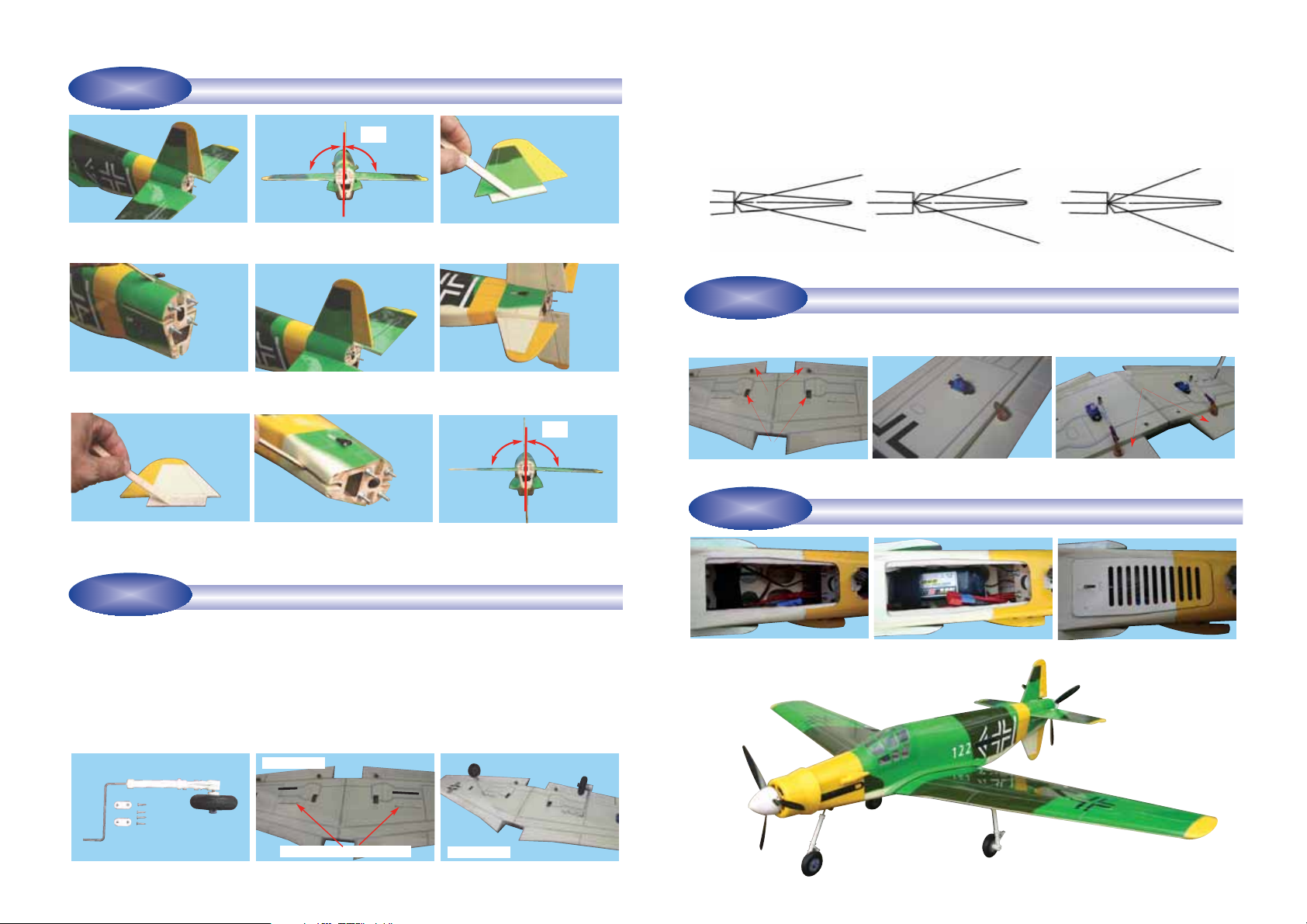
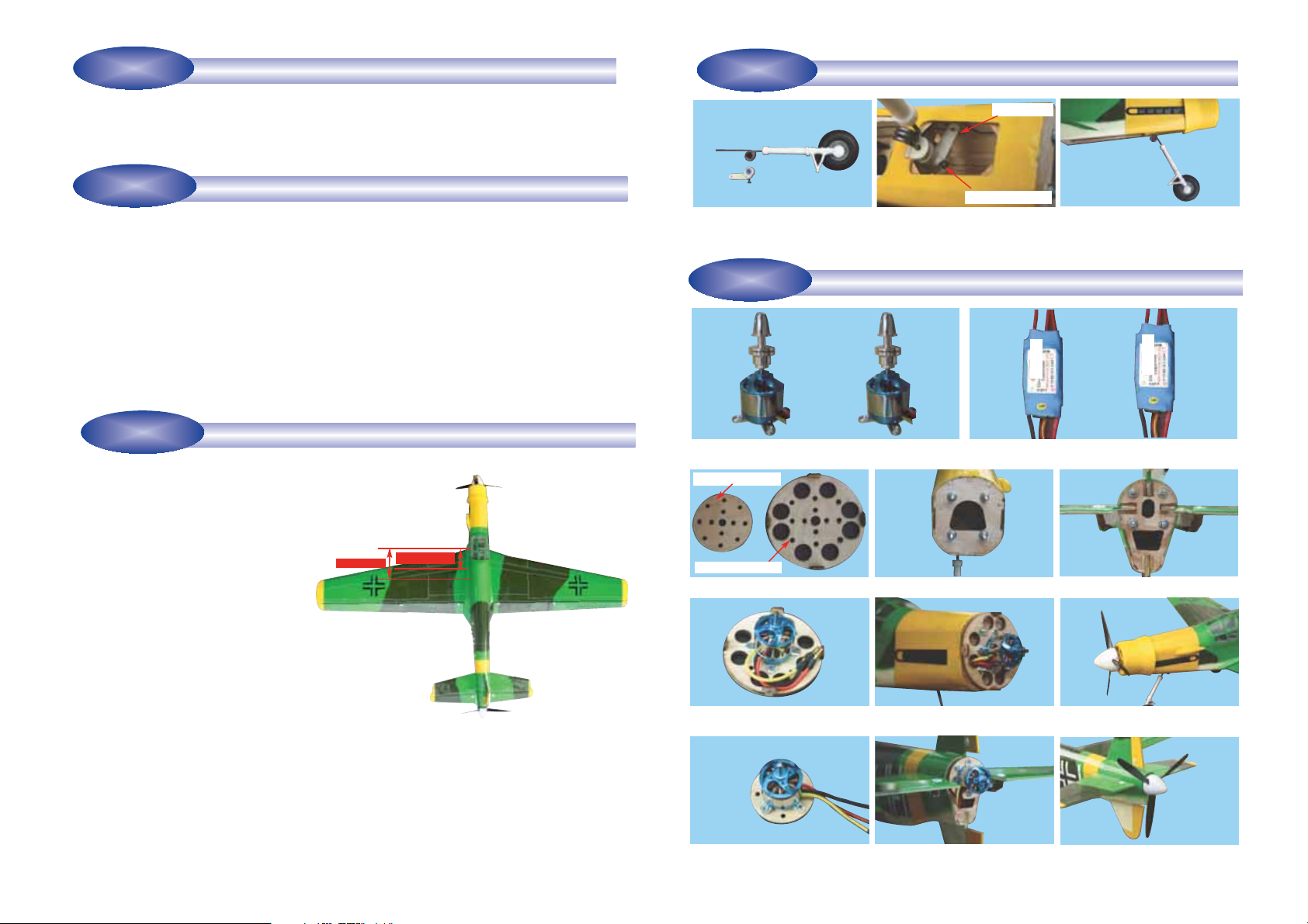
10A- Nose gear assembly 10C- Nose gear assembly installed to
the fuselage (side view)
10B- Insert the nose gear steering
control arm to the EZ connector then
insert the nose gear assembly into
the nose gear bearing then tighteng
the control arm screw
11C- Front and rear motor mount
11F- Mount the brushless motor to
the front motor mount
11I- Mount the brushless motor to the
rear motor mount
11G-The front motor mount with the
motor install to the nose
11H- Cowl,propeller and spinner are
installed to the nose
11H- Cowl,propeller and spinner
installed to the rear end
11D- Front motor location 11E- Read motor mount location
11B- The pair of the suitable ESC come with motor
11A- Front and rear brushless motors are same 150 watts
brushless motor recommended
INSTALL THE NOSE GEAR
STAGE 10
INSTALLING THE ELECTRIC MOTOR AND ESC
STAGE 11
Control arm screw
Front motor mount
Rear motor mount
EZ connector
E
S
C
E
S
C
11G-The rear motor mount with the
motor install to the rear end
CONFIRM RADIO OPERATION
STAGE 18
Step 18.1 Consult your radio manual for instructions about
testing and operating your radio system.
Step 18.2 Pay particular attention to charging your batter-
ies and range testing your system before and after each
flight.
Step 18.3 Check that all controls are working correctly
before and after each flight.
BALANCING THE AIRCRAFT
STAGE 19
Step 19.1 The CG for your DO 335 is located at 3.1/2 in to
4 in (87mm - 102mm) back from the leading edge of the
wing when the wing has been attached to the fuselage as
per illustration 20A.
Step 19.2 For the initial flight, the CG should be located at
3.1/2 (87mm) back from the leading edge of the wing when
the wing has been attached to the fuselage.
Step 26.3 The CG is measured with the engine,radio gear
and all other components installed
Step 26.4 Set up the CG as it will be when you fly it.
Step 26.5 It is very important to have the CG correct. Flying
your model with the CG too far back will likely lead to loss
of control and a crash. If you discover that after you have
assembled your model and installed your radio, motor and
battery that the CG of your model is incorrect you must
bring the CG to the correct location by doing the following
BEFORE FLYING :
- Move the battery pack fore or aft
- Move other components fore or aft
- Change engine to a lighter or heavier model
- Add weight to the nose or tail. If adding it to the nose,try
to make it useful by going to a heavier duty engine or
adding a spinner with a heavy metal backing plate. As a last
resort, add stick on “dead” weight where appropriate
CONFIRM MECHANICAL INTEGRITY
STAGE 20
Step 20.1 Once you have confirmed that the
CG is correct, you should do a thorough review
of the entire model before your first flight.
Check everything twice! Every hook up, every
coupling, everything! Do it twice!!
Step 20.2 Before your first flight, have an
experienced flyer review your work. Do not fly
your model until it has been checked out by a
third party who knows how to fly and how to
set up a model aircraft. Do not fly alone. Seek
experienced help.
Step 20.3 Once you have completed your first
flight, get in the habit of checking your model over
before and after each flight! Don’t fly if you find
something that is not right!
3.1/2in (152mm)
4in (102mm)
27A - CG location
CONTROL SURFACE THROW SPECIFICATIONS:
The throws are measured at the widest part of the control
surface. Adjust the position of the pushrods at the control
and/or servo horns to control the amount of throw. You may
also use ATV's if your radio has them but the mechanical
linkages should still be set so that the ATV's are near 100%
for best servo resolution.

89
FITTING THE ELEVATOR AND RUDDER CONTROL HORN
STAGE 12
12A- Elevator control horn location
12B- Rudder control horn location 12C- Elevator control horns and rudder control horn installed in its loca-
tion and connected to the clevises
13A- Elevator and rudder servos location 13B- Elevator servo connected to the elevator control
rod,rudder servo connected to the rudder and gear steer-
ing control rod
INSTALL THE RUDDER AND ELEVATOR SERVOS
STAGE 13
Elevator servo location Elevator control rod
Rudder control rod Nose steering control rod
Rudder servo location
LIPO BATTERY
FRONT MOTOR
Use Y connector to connect the front and
the rear ESC speed control signal then plug
into the receiver throttle control channel
( Do not connect the power from BEC on
the ESC to the receiver )
FRONT MOTOR ESC
REAR MOTOR ESC
RECEIVER
RECEIVER BATTERY
REAR MOTOR
50 AMP FUSE
Typical wiring diagram of the brushless motor systems for DO 335 EP model
Elevator control horn
Rudder control horn
ADJUST CONTROL SURFACE THROW LIMITS
STAGE 14
Adjust the deflection of the control surfaces to match the
specifications on page 8. You can reduce the amount of
throw by doing either or both of the following:
- From the servo end, move the clevis to a hole in the servo
arm that is closer to the servo output shaft.
- From the control horn end, move the control rod/clevis fur-
ther out on the horn (away from the control surface).
Always confirm that the clevis is firmly attached after mak-
ing any adjustment.
FINAL RC SET-UP
STAGE 15
Before starting the final set-up of the model, switch on the radio and ensure that all trims are in their neutral positions.
Check that the ailerons, elevator and rudder are centered. If any adjustments are needed, do these by uncoupling the rel-
evant clevis and turning it clockwise to shorten the linkage or counter - clockwise to lengthen it. Only when each control
surface has been centered mechanically in this way should you begin adjusting the surface movement (or throw)
Now confirm that the control surfaces are moving in the correct direction. Use the servo reversing switches on your trans-
mitter to reverse the direction of a servo if necessary. The most popular transmitter mode (with the throttle on the left, with
ailerons and elevator on the right) is shown here.
INSTALLING THE RECEIVER BATTERY
STAGE 16
Step 16.1 Consult your radio manual for instructions about
hooking up your receiver battery, receiver and swich har-
ness
Step 16.2 Wrap the battery pack securely in foam suitable
for RC equiment and wrap the foam insulated pack in a
plastic bag or cling wrap.
Step 16.3 Thread the battery pack connector forward in
preparation for connecting to your swich harness
Step 16.4 Connect the battery pack connector to your
switch harness according to your radio manual
We recommended to use separate receiver battery do not
use BEC from ESC
INSTALLING THE RECEIVER
STAGE 17
Step 17.1 Consult your radio manual for instructions about
hooking up your receiver.
Step 17.2 Plan where you are going to put the receiver with
consideration for routing the antenna safely.
Step 17.3 Wrap the receiver securely in foam suitable for
RC equipment and wrap the foam insulated receiver in a
plastic bag or cling wrap.
Step 17.4 Generally in the absence of specific instructions
from the radio manufacturer, it is recommended that the
receiver should be placed where it is least likely to have
impact during a crash. Keep the battery pack and other
heavy loose items ahead of the receiver.
Table of contents
Other Polycote ECS Toy manuals
Popular Toy manuals by other brands

Faller
Faller HOUSE OF EMMENTAL manual

Faller
Faller BEETHOVENSTRASSE 2 TOWN HOUSES manual

Mattel
Mattel Mega Bloks Hot Wheels Street Speeder quick start guide

Mattel
Mattel Roll Cage Tyco RC user guide

JAKKS Pacific
JAKKS Pacific World of Nintendo Mariokart 7 manual

Fisher-Price
Fisher-Price V5709 quick start guide