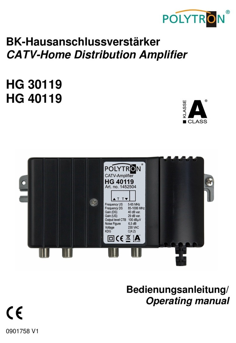
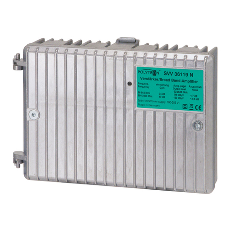
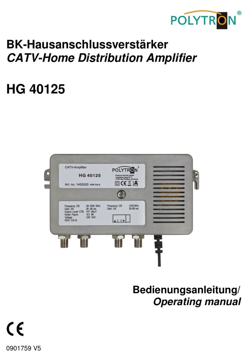
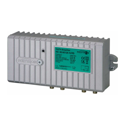
Polytron CV 30 126 N User manual

2
Sicherheitshinweise
Vor Inbetriebnahme des Polytron Gerätes bitte unbedingt die Sicherheits- und Be-
dienhinweise lesen!
Wichtig: Die Installation des Gerätes sollte nur von Fachpersonal durchgeführt
werden. Vor Beginn von Servicearbeiten das Gerät von der Spannungsversorgung
trennen, da beim Öffnen des Gehäuses spannungsführende Teile freigelegt wer-
den, die bei Berührung lebensgefährlich sein können.
Um die Störstrahlsicherheit des Verstärkers zu garantieren, muss der Ver-
stärkerdeckel nach dem Öffnen wieder fest verschraubt werden!
Umgebungstemperatur Die Umgebungstemperatur darf den Bereich von 0°C bis
+50°C nicht überschreiten.
Netzanschluss und Netzkabel
Bei Geräten mit der Netzteil-Schutzklasse I muss der gelb/grüne Leiter mit dem
Steckeranschluss "E" oder verbunden werden. Der blaue Leiter muss mit dem
Anschluss "N" und der braune Leiter mit dem Anschluss "L" verbunden werden.
Geräte die mit einer Fernspeise-Stromversorgung arbeiten, dürfen auf keinen Fall
an 230 V~ angeschlossen werden, sonst besteht Lebensgefahr!
Bei Geräten mit der Netzteil-Schutzklasse II muss das Gehäuse des Gerätes an
der in der Bedienungsanleitung angegebenen Stelle geerdet werden. Der Schutz-
leiter ist in diesem Fall nicht angeschlossen.
Erdung der Anlage
Nach den EN 50 083 / VDE 0855 Bestimmungen muss die Antennenanlage den
Sicherheitsbestimmungen wie z.B. Erdung, Potenzialausgleich, etc. entsprechen.
Bedingungen zur Sicherstellung der elektromagnetischen Verträglichkeit
(EMV)
Alle Abdeckungen und Schrauben müssen fest montiert und angezogen sein, Kon-
taktfedern dürfen nicht oxidiert oder verbogen sein.

3
1 Beschreibung
Die Verteilnetzverstärker der CV-Serie mit einer Ausgangsspannung 126 dBµV bei
862 MHz bieten vielseitige Einsatzmöglichkeiten. Die Typen CV 30126 und
CV 40126 mit einer max. Verstärkung von 36 dB bzw. 40 dB eignen sich bestens
als Verteilverstärker in den C-Linien.
Die Serie beinhaltet jeweils eine orts- als auch eine ferngespeiste Version mit ei-
nem Stromdurchgang von bis zu 7 A, so dass der Aufbau eines flexiblen Versor-
gungskonzeptes gewährleistet werden kann.
Die CV-Serie besitzt Steckplätze für Steckentzerrer, Dämpfungsglieder
oder Entzerrer und Regelmodule.
Durch den flexiblen Einsatz von Rückkanalmodulen können Mehrzweckdienste
(z.B. Internet) in Kabelnetzen genutzt werden.
Die Ausgänge können Vorort mit Verteil- bzw. Abzweigmodulen bestückt werden.
Ein Verteilmodul ermöglicht zwei gleichberechtigte Ausgänge, die beide um -4 dB
abgesenkt werden. Die Abzweigmodule reduzieren den zweiten Ausgang um -7 dB
oder -14 dB. Der zweite Ausgang kann bei Bedarf zu einer externen Messbuchse
mit -20 dB geschaltet werden. Am ersten Ausgang ist in diesem Fall das Aus-
gangssignal um 1 dB gedämpft.
Da alle Ein- und Ausgänge in PG11-Technik ausgeführt sind, ist der Anschluß von
IEC-, F- oder anderen Steckern möglich. (Werksausstattung: ohne Buchsen)
Auch gemischte Anschlußnormen, z.B. für Kabel mit unterschiedlichen Durchmes-
sern, sind möglich. Der Verstärker ist an allen Ein- und Ausgängen zuverlässig ge-
gen Überspannungen geschützt.
Achtung Beim Anschließen des
Verstärkers ist der zulässige Aus-
gangspegel zu beachten. Der Verstär-
ker wird mit zugedrehtem Dämpfungs-
regler (-20 dB) ausgeliefert. Beim Ein-
stellen des Gerätes auf die gewünsch-
te Verstärkung, ist die übliche Tabelle
(siehe unten) zur Pegelreduzierung in
Abhängigkeit der Anzahl der Kanäle zu
berücksichtigen. Bei Nichtbeachtung
kann das Gerät beschädigt werden.
Anzahl der
belegten Kanäle
Pegelreduzierung
in dB
2
-0
3
-2
4
-3
5
-4
6
-5
7
-5,5
8
-6
10
-7
12
-8
16
-9
24
-11
36
-12,5

4
2 Einstellungen
Serienmäßig sind die CV-Verstärker mit Steckbrücken ausgestattet. Die Verstärker
werden mit einer linearen Verstärkercharakteristik im Vorwärts- als auch Rückkanal
ausgeliefert. Dazu befinden sich in den Entzerrer-Steckplätzen Brücken.
Die Polytron Modulserie bietet Entzerrer-Module im Vorwärtszweig für die Fre-
quenzgrenze 450, 606 und 862 MHz und beim Rückkanal für die Frequenzgrenze
30 und 65 MHz an.
Generell gilt, dass die obere Frequenzgrenze des Entzerrers sowohl im Vorwärts-
zweig als auch im Rückkanal mit derjenigen der Anlage identisch sein sollte. Ober-
halb der spezifizierten Frequenz fällt die Entzerrungskurve steil ab.
Eine vollständige Übersicht der verfügbaren Steckmodule finden Sie in Kapitel 4.
13
1
2
3
4
5
6
7
8
9
2
10
11
12
12
4

5
(1) Signaleingang (PG 11 oder F)
(2) Line Out
Je nach Bestückung mit einem Verteil-
bzw. Abzweigmodul liefert dieser Aus-
gang ein nicht verstärktes Signal mit
einer Dämpfung zwischen -1 und -4
dB. Über die Buchse kann die Fern-
speisespannung auch in der Strecke
zugeführt werden. (Werksausstattung:
Line out nicht belegt).
(3) Eingangsmessbuchse
Bidirektionale Messbuchse zur Mes-
sung des Eingangssignals ohne Be-
triebsunterbrechung
(4) Rückkanaldiplexer
Der Rückkanal kann je nach Bedarf mit
einer Frequenzobergrenze von 30 oder
65 MHz realisiert werden. Der Vor-
wärtskanal beginnt dann bei 47 bzw.
86 MHz. (Werksausstattung: Brücke,
nur Vorwärtskanal aktiv).
(5) Entzerrer vor der ersten
Verstärkerstufe
Ein Entzerrer kompensiert die mit der
Frequenz zunehmende Dämpfung
passiver Bauteile in der Anlage. Vor
der ersten Verstärkerstufe sorgt er da-
für, dass diese nicht übermäßig durch
niedrige Frequenzanteile belastet wird.
Er erhöht allerdings hier entsprechend
seiner Dämpfung das Rauschmaß bei
niedrigen Frequenzen. Nach Möglich-
keit ist deshalb zuerst ein Entzerrer
hinter der ersten Verstärkerstufe zu
bestücken. (Werksausstattung: Brücke
für linearen Frequenzgang).
(6) Variabler Pegelsteller
Durch diesen Pegelsteller wird die ma-
ximal mögliche Verstärkung im Vor-
wärtszweig auf den gewünschten Wert
reduziert und somit der Ausgangspegel
eingestellt.
(7) Entzerrer nach der ersten Ver-
stärkerstufe
Ein Entzerrer oder ein Dämpfungsstel-
ler (max -6 dB) lässt sich an dieser
Stelle bestücken, ohne dass sich der
maximale Ausgangspegel verringert.
Der große Vorteil besteht darin, dass
das Rauschmaß des Verstärkers nur
leicht ansteigt. (Werksausstattung:
Brücke für linearen Frequenzgang).
(8) Aktiver / passiver Rückkanal
Der Rückkanal lässt sich mit Verstär-
kung (aktiv) oder ohne (passiv) auf-
bauen. Die Verstärkung bzw. Dämp-
fung im Rückkanal wird mit dem im
Steckmodul eingebauten Pegelsteller
justiert. (Werksausstattung:
Brücke nicht bestückt)
(9) Rückkanalentzerrer
Ein Entzerrer im Rückkanal sorgt da-
für, dass der frequenzabhängige
Dämpfungsverlauf im Rückkanalzweig
ausgeglichen werden kann. (Werks-
ausstattung: Brücke für linearen Fre-
quenzgang).
(10) Ausgangsmessbuchse
Die Messbuchse liefern ein um - 20 dB
gedämpftes Signal und erlaubt deshalb
die Durchführung von Installations- und
Serviceaufgaben ohne Betriebsunter-
brechung, da die Buchsen spannungs-
frei sind.
(11) Variable Ausgangskonfigura-
tion
Mit den Verteil- und Abzweigmodulen
können ein oder zwei Betriebsausgän-
ge oder alternativ ein Betriebs- und ein
Input
Line out
Output 2
Output 1

6
Messausgang realisiert werden.
Dadurch ist z.B. die Verteilung des
Signals auf mehrere Linien oder das
Durchführen von Messungen ohne Be-
triebsunterbrechung und ohne das Öff-
nen des Verstärkers möglich. (Werks-
ausstattung: Brücke).
(12) Signalausgang 1 / 2
(13) Fernspannungsversorgung
Der Stromdurchgang ist für alle Ein-/
Ausgänge des Verstärkers durch Si-
cherungen getrennt schaltbar. Durch
Bestückung mit den beiliegenden Si-
cherungen ist es möglich, die Fern-
speisspannung zu jedem Eingang bzw.
Ausgang durchzuschalten.
3 Tausch des Deckels und Wechseln des Netzteils
Bei den CV-Verstärkern lässt sich der Deckel mit integriertem Netzteil leicht ab-
nehmen und tauschen. Der Tausch des Netzteils erlaubt z.B. vor Ort die Umstel-
lung von Ortsspeisung auf Fernspeisung. Auch im Servicefall ist der Netzteiltausch
besonders einfach: Die Konfiguration des Verstärkers mit allen Steckmodulen, Pe-
geleinstellungen sowie Schalterstellungen bleibt erhalten.
1. Inbusschrauben lösen und Verstärker
öffnen.
2. Steckverbindung zwischen Netzteil
und Verstärkerplatine lösen
3. Scharnier mit einem Handgriff aus-
hängen.
4. Neuen Deckel einsetzen, Steckverbin-
dung wieder herstellen und Deckel
verschließen.
Input
Line out
Output 2
Output 1

7
Safety instructions
All safety and operation instructions should be read before this Polytron product is
operated.
Important: Only qualified persons should install the device. To prevent electric
shock, unplug power supply before carrying out service work. Open devices access
dangerous voltages which contact may endanger your life.
To guarantee the EMC protection of the amplifier the lid must be bold tight
again after opening the amplifier.
Ambient temperature The ambient temperature should not exceed a range of 0 C
to + 50°C (32°F to 122°F).
Mains connection and mains cable
At devices of power supply safety class I, the green/yellow coloured wire must be
connected to the terminal plug marked with letter "E" or earth symbol . The blue
coloured wire must be connected to the terminal marked "N" and the brown col-
oured wire to the terminal marked "L".
Remote feeding supply operating devices may not be connected to 230 VAC. This
could endanger your life! At devices of the power supply safety class II, the housing
of the device must be connected to ground at the place indicated in the operating
instructions of the device. The earthing equipment conductor is not connected in
this case.
Grounding of system
According to EN 50 083 / VDE 0855 regulations, the antenna system must comply
with the safety regulations e.g. grounding, potential equalisation etc.
Precautions to ensure the electromagnetic compability (EMV)
All covers and screws must tightly be fitted and should be tightly fastened. Contact
springs should not be oxidated or deformed.

8
1 Description
The line distribution amplifiers of the CV series with an output level of 126 dBµV at
862 MHz can be used in many applications. The types CV 30126 and CV 40126
with a max. amplification of 36 dB or 40 dB can be used as network amplifiers for C
lines.
The series contains versions with mains supply or remote feeding, all with a transit
current up to 7 A, allowing a flexible power supply concept.
The amplifiers include slots for point attenuators, equalizers or attenuators and
AGC module.
The use of active or passive return path modules can support multimedia services
(e.g. Internet) in cable networks.
The outputs can be equipped with distribution or splitter modules. A distribution
module enables two equal outputs, which both can be reduced by -4 dB. The split-
ter modules reduce the second output by -7 dB or -14 dB. If required the second
output can be switched to an extern test sockets. In this case the output signal at
the first output is attenuated by 1 dB.
All input and outputs are in PG11 technology, which allows the connection of IEC,F
and other plugs. (Factory setting: without sockets)
Mixed connection standards, e.g. for cables with different diameter are also possi-
ble. The amplifier is well protected against high tension on all inputs and output
Attention When connecting the ampli-
fier please pay attention to the max.
permissible output level. The variable
attenuator is turned to max. attenuation
(-20 dB) upon leaving the factory.
When setting the amplifier to the re-
quired amplification, the usual table
(see below) for level reduction in rela-
tion to the number of channels must be
taken into consideration. Please note
that an excessive power level can
damage the amplifier.
Number of
occupied channels
Level reduction
in dB
2
-0
3
-2
4
-3
5
-4
6
-5
7
-5,5
8
-6
10
-7
12
-8
16
-9
24
-11
36
-12,5

9
2 Settings
The CV amplifier series is generally equipped (ex factory) with bridges in all slots.
The amplifiers are manufactured with a flat frequency response through-out the
forward and reverse band. For this purpose upon delivery all slots are fitted with
bridges.
The Polytron module series supplies equalizers for 450, 606 and 862 MHz for the
forward-path and 30 and 65 MHz for the return-path.
Generally the upper frequency barrier
of the attenuator of the forward and the return path should be the same as the up-
per frequency barrier of the unit. Above the specified barrier the attenuator curve
slopes.
You will find a module overview in chapter 4.
13
1
2
3
4
5
6
7
8
9
2
10
11
12
12
4

10
(1) Signal input (PG11 or F)
(2) Line Out
Depending on the assembly of distribu-
tion or splitter modules this output de-
livers a looped-through input signal at-
tenuated from –1 to –4 dB.
Additionally the remote feeding voltage
can be fed in line via this socket. (Fac-
tory setting: not active -Jumper bridge)
(3) Input test socket
Bi-directional test socket for measure-
ment of input signal without operation
interruption.
(4) Return path diplexer
The return path diplexer can be config-
ured depending on capacity needs, for
a frequency range up to 30 or 65 MHz.
The forward path begins at 47 resp. 86
MHz. (Factory setting: Jumper bridge,
only forward path is active).
(5) Equalizer in front of first ampli-
fier stage
An equalizer compensates the increa-
sing attenuation of passive compo-
nents at higher frequencies. It ensures
that the first amplification stage is not
overburdened with low frequency
parts. However, at this place it in-
creases the noise figure at lower fre-
quencies, dependent on its attenua-
tion. If possible it is therefore recom-
mended to place an equalizer behind
the first amplifier stage.
(6) Variable attenuator
The variable attenuator allows the
maximum amplification setting to be
reduced to the required amplification in
the forward path, thus enabling the ad-
justment of the output level.
(7) Equalizer after the first amplifier
stage
An equalizer or a variable attenuator
(max -6 dB) can be installed at this
point. The output level will not change.
The main advantage is that the noise
figure of the amplifier is not increased
hereby. (Factory setting: Jumper
bridge for linear frequency response).
(8) Active / passive return path
The return path can be built-up with
amplification (active) or without (pas-
sive). The amplification resp. attenua-
tion of the return path is adjusted with
the built-in attenuator of the plug-in
module. (Factory setting: Jumper
bridge).
(9) Return path equalizer
An equalizer in the return path ensures
that frequency dependent attenuation
differences could be compensated.
(Factory setting: Jumper bridge for lin-
ear frequency range).
(10) Output test sockets
On the test socket the signal is availa-
ble as -20 dB attenuated signal and
thus it allows measurements and ser-
vice activities without interrupting the
operation.
(11) Variable output configuration
Two operating outputs or alternatively
one operating and one test output can
be configured with splitter and tap
modules. Thus it is possible to either
distribute the signals on more than one
line, or make measurements without
affecting the operation nor having to
open the amplifier. (Factory setting:
Jumper bridge).
11
(12) Signal output 1/2
(13) Remote feeding
Remote feeding of the input and output
can be separately set by fuses. It is
possible to switch the remote feeding
voltage to the input or output by as-
sembling with the enclosed fuses
3 Removing lid and changing power supply
The CV range allows an easy removal and replacement of the lid integrated power
supply. Changing of the power supply lid allows the amplifier to be reconfigured
from mains to remotely fed supply. In service cases this is especially convenient:
The configuration of the amplifier with all plug-in modules, level settings as well as
switch setting are retained.
1. Loosen the screws and open amplifier.
2. Remove power supply connection be-
tween lid and amplifier board.
3. Hinge-out lid with one hand grip.
4. Place new lid, reconnect power supply
connection and close lid.
Input
Line out
Output 2
Output 1

12
Consignes de sécurité
Avant la mise en service de l'équipement, veuillez lire les consignes de sécurité
ainsi que le mode d'emploi !
Important : L'installation de l'appareil doit être effectuée par un personnel qualifié.
Avant toute intervention sur l’appareil, veuillez débrancher l'alimentation électrique.
Lors d’une intervention sur un appareil en fonction, veuillez veiller lors de l'ouver-
ture du couvercle de ne pas toucher les parties restées sous tension. Tout contact
peut être mortel.
Afin d’empêcher tout rayonnement vers l’extérieur de l’amplificateur, il est recom-
mander de bien resserrer les vis de serrage du couvercle.
Température ambiante: la plage de la température de fonctionnement ambiante
est de 0°C à 50°C maximum.
Alimentation et raccordement d’un cordon d'alimentation
Pour les appareils électrique de la catégorie I, le conducteur de couleur jaune/vert
doit être raccordé au branchement repéré par « E » ou .
Le conducteur bleu doit être raccordé au branchement repéré « N » et le conduc-
teur brun doit être raccordé au branchement repéré « L ».
Les appareils destinés à fonctionner en mode télé alimentation, ne doivent pas être
raccordés au secteur 230 VAC sous risque de destruction générale de l’appareil.
Cette action représente un danger de mort !
Pour les appareils électrique de la catégorie II, la mise à la terre du boitier est obli-
gatoire et à effectuer comme décrit dans le manuel d'utilisation.
Mise à la terre du système
Conformément aux dispositions EN 50 083 / VDE 0855, le système d'antenne doit
être installé dans le respect des normes de sécurité en vigueur concernant la mise
à la terre, la liaison équipotentielle, etc.
Garantie de la compatibilité électromagnétique de l’appareil.
Toutes les vis de fixation du couvercle doivent être en place et serrées. Les res-
sorts de contact entre les deux parties du boitier ne doivent pas être oxydés, ni dé-
formés.

13
1 Description
Les amplificateurs de ligne ou de distribution de la gamme CV disposent d’un ni-
veau de sortie de 126 dBµV à 862 MHz.
L’utilisation d’un hybride GaAs-Fet pour l’étage de sortie de certains modèles per-
met d’obtenir und fort niveau de sortie et de répondre ainsi à tout type réseaux de
télédistribution-
Les amplificateurs de la gamme CV sont disponibles en version secteur ou téléali-
menté. La téléalimentation peut s'effectuer par l'entrée ou la(les) sortie(s). Le pas-
sage de la téléalimentation sur l'entrée ou la sortie est également possible.
Les modules enfichables permettent une adaptation optimale aux besoins the ré-
seaux de télédistribution. Les bandes de fréquence, l’atténuation, l’égalisation, la
voie de retour passive ou active, l’entrée et la sortie sont des paramètres configu-
rables. La modularité des amplificateurs est un gage d'économie et de pérennité.
Elle permet également une maintenance aisée et une réponse à l'évolution future
des réseaux de télédistribution.
Important
L'amplificateur est livré avec son atténuateur
réglable positionné à -20 dB.
Lors de la mise en œuvre de l'amplificateur, le
niveau de sortie maximum de l’amplificateur à
respecter doit tenir compte du facteur de ré-
duction lié au nombre de canaux transmis
dans l’installation. Voir tableau ci-après. La
valeur de réduction maximale à prendre en
compte au-delà des 36 canaux est de 12 dB.
Le non-respect de ce point peut endommager
l'appareil.
Nombre de canaux
Réduction de
gain en dB
2
-0
3
-2
4
-3
5
-4
6
-5
7
-5,5
8
-6
10
-7
12
-8
16
-9
24
-11
36 et +
-12

14
2 Configuration du Produit
Les amplificateurs de la série CV sont équipés en sortie d’usine de ponts enfi-
chables 0 dB, permettant une utilisation du produit en tant que amplificateur large
bande 4 –862 MHz.
Selon la configuration souhaitée, le large choix dans les différents modules enfi-
chables à valeurs fixes ou variables, permet de configurer la bande passante (V.R.
de 5 –30 ou 5 –65 MHz), l’égalisation et/ou atténuation en inter-étage, ainsi que
le type de voie de retour active ou passive.
Aperçu complet des modules disponibles au chapitre 4
1
2
3
4
5
6
7
8
9
2
10
11
12
12
4

15
(1) Signal d'entrée
Accès PG 11
(2) Line Out
Qu’elle soit assemblée avec un module
de dérivation ou de distribution, cette
sortie fournit un signal non amplifié
avec une atténuation entre -1 et -4 dB.
La tension d'alimentation à distance de
la gamme peut être alimentée via la
prise. (ex. usine: Line Out non utilisée).
(3) Point test d‘entée
Point test bidirectionnel permettant la
mesure des signaux sans interruption
du service.
(4) Filtre de voie de retour
Choix des bandes passantes à l’aide
du type de module filtre: 86 –862 MHz
/ 5 –30 MHz ou 47 –862 MHZ / 5 –65
MHz
(5) Egaliseur
Emplacement pour modules égaliseurs
ou atténuateurs fixes ou variables.
(6) Atténuateur
Permet d’ajuster le niveau de travail de
l’amplificateur
(7) Module inter-étage
Emplacement pour atténuateurs ou
égaliseurs (fixe ou variable) en inter-
étage.
(8) Voie de retour active ou passive
Différentes possibilités en fonction du
module utilisé. Equipés d'un atténua-
teur réglable et d’un égaliseur en fonc-
tion du modèle.
(9) Egaliseur voie de retour
Modules égaliseurs fixes ou réglables.
(10) Point test
Point test permettant la mesure des si-
gnaux de sortie sans interruption de la
distribution du signal.
(11) Modules de sortie
En fonction du module utilisé nous dis-
posons de :
Une sortie unique
Une sortie et une sortie test
Deux sorties symétriques ou asy-
métriques
(12) Sortie HF 1 / 2
(13) Téléalimentation
Disponible uniquement sur la version
CV …F. Configuration passage de la
téléalimentation par fusibles enfi-
chables.
Input
Line out
Output 2
Output 1

16
3 Échange du cache et changement de l'alimentation
Les caches avec l’alimentation intégrée des amplificateurs de CV peuvent facile-
ment être enlevés et remplacés.
Le remplacement de l’alimentation permet, par exemple, la conversion, de
l’alimentation locale en téléalimentation sur le site.
Le remplacement est très facile même en service.
La configuration de l'amplificateur avec les modules, les réglages de niveau et les
positions du commutateur est conservée.
1. Desserrer la vis Allen et ouvrir l'ampli-
ficateur.
2. Desserrer la prise de connexion entre
l'alimentation et la platine d'amplifica-
teur.
3. Décrocher la charnière d’une main.
4. Insérer le nouveau cache, rétablir la
prise de connexion et fermer le cache.

17
4 Technische Daten / Modulübersicht
Technical date / module overview
Caractéristiques techniques / Sommaire des modules
Typ / Type
CV 30126
CV 40126
Frequenzbereich / frequency range/
Bande passante
4-862 MHz
Rückkanal / return path / Voie de re-
tour
steckbar 30 / 65 MHz
Verstärkung / gain / Amplification
V.D.
30 dB
40 dB
Linearität / flatness / Linéarité
≤ 7,5 dB
≤ 6,5 dB
Variabler Pegelsteller / variable at-
tenuator / Atténuateur variable
- 20 dB
Rauschmaß / noise figure / Facteur
de bruit
± 0,5 dB
Entzerrer-Steckplätze/ equalizer slots
/ Emplacement d‘égalisation
2
Ausgangspegel / output level /
Niveau de sortie
862 MHz
60 dB IMR3
126 dBµV
60 dB IMR2
118 dBµV
60 dB CTBA
112 dBµV
60 dB CSO
113 dBµV
Rückflussdämpfung / return loss /
Adaption d’impédance
20 dB - 40 MHz (-1,5 dB/ Oktave)
Endstufe / final stage / Etage de sor-
tie
GaAS-FET
Leistungsaufnahme / power con-
sumption / Consommation
13 W
Stromdurchgang / transit current /
Passage de téléalimentation
CV…F: 7 A
Maße (B x H x T) / dimensions (w x h
x d) / Dimension du boîtier (L x I x H)
242 x 163 x 90 mm
Gewicht / weight / Poids
3,15 kg
Schutzklasse
protection class
IP 66
Spannungsversorgung / voltage
supply/ Tension d‘alimentation
CV…N: 180-255 V~
CV…F: 24-70 V~

18
Rückkanalmodule ak-
tiv/passiv
sind als aktive oder pas-
sive Ausführung erhält-
lich. Die Verstärkung
bzw. Dämpfung wird
durch den Pegelsteller in
einem Bereich von 10
dB eingestellt. Die
Rückkanal-Module
VMR…E haben bereits
einen Entzerrer inte-
griert.
Return path module
active/passive
are available as active
version and as passive
version. Amplification or
attenuation is adjusted
in a 10 dB range by a
variable attenuator. The
return path modules
VMR...E provide an in-
tegrated equalizer.
Modules de voie de re-
tour active/passive
Modules de configura-
tion de la voie de retour
active ou passive. Les
modules sont équipés
d'un atténuateur réglable
0 à 10 dB. Les modules
VMR…E ont un égali-
seur intègre.
Typ / Type
VMR 0
VMR 12
VMR 24
VMR 12 E
VMR 24 E
Verstärkung /
amplification
-10 –0 dB
2 –12 dB
14 –24 dB
2 –12 dB
14 –24 dB
Ausgangspegel /
output level/
niveau de sortie
113 dBµV
113 dBµV
113 dBµV
113 dBµV
113 dBµV
Entzerrung/
equalisation /
egalisation
-
-
-
0-10 dB
0-10 dB
Artikel-Nr. / article
no./ référence
1481500
1481700
1481600
1481710
1481610

19
Rückkanaldiplexer
trennen den Vorwärts-
und Rückkanal zur se-
paraten Verstärkung auf.
Dazu wird ein Diplexfilter
am Ausgang und am
Eingang eines Verstär-
kers eingesetzt.
Return path diplexer
split the forward and re-
turn path for separate
amplification. Therefore
a filter is placed at the
input and output slots of
the amplifier.
Diplexeur de voie de
retour.
Les 2 modules configu-
rent en entrée et en sor-
tie amplificateur les
bandes de fréquences
de la voie descendante
et de retou
Entzerrer
kompensieren die zu-
nehmende Dämpfung
passiver Bauteile zu hö-
heren Frequenzen.Die
Entzerrer gibt es sowohl
mit gestuften als auch
mit einstellbaren Wer-
ten.
Equalizers
compensate the increas-
ing attenuation of pas-
sive components to
higher frequencies.The
equalizers are available
with stepped values as
well as with adjustable
ones.
Egaliseur
compense la non linéari-
té des pertes du câble
en fonction des fré-
quences.
Des modules à valeur
fixe ou réglable sont
proposés.
Typ / Type
VMF 3
VMF 6
Frequenzbereich / frequency range /
Bande passante
4 –30 MHz
4 –65 MHz
Durchgangsdämfung / through loss /
Perte de passage
0,5 dB
0,5 dB
Artikel-Nr. / article no./ Référence
1484500
1484700

20
Festentzerrer / Fixed equalizers / Egaliseurs fixes
Typ / Type
VM 4-6
VM 4-12
VM 6-6
VM 6-9
VM 6-12
Frequenzbereich / frequency range/
Bande passante
47 –450 MHz
47 –606 MHz
Entzerrung / equalization/
Egalisation
6 dB
12 dB
6 dB
9dB
12 dB
Grunddämpfung / basic loss/
Perte d’insertion
-1 dB
Artikel-Nr. / article no. / référence
1472500
1472700
1473000
1473100
1473200
Festentzerrer / Fixed equalizers / Egaliseurs fixes
Typ / Type
VM 8-3
VM 8-6
VM 8-9
VM 8-12
Frequenzbereich / frequency range/
Bande passante
47 –862 MHz
Entzerrung / equalization/ Egalisa-
tion
3 dB
6 dB
9 dB
12 dB
Grunddämpfung / basic loss/
Perte d’insertion
-1 dB
Artikel-Nr. / article no. / référence
1472400
1473500
1473600
1473700
Variable Entzerrer / Variable equalizers / Egaliseurs variables
Typ / Type
VM 4
R-10
VM 4
R-20
VM 6
R-10
VM 6
R-20
VM 8
R-10
VM 8
R-20
Frequenzbereich
/ frequency range/
Bande passante
47 –450 MHz
47 –606 MHz
47 –862 MHz
Entzerrung /
equalization/
Egalisation
0 - 10 dB
0 –20 dB
0 - 10 dB
0 –20 dB
0 - 10 dB
0 –20 dB
Grunddämpfung /
basic loss/
Perte d’insertion
-1 dB
Artikel-Nr. / ar-
ticle no. / Réfé-
rence
1476500
1476600
1476800
1476900
1477100
1477200
This manual suits for next models
3
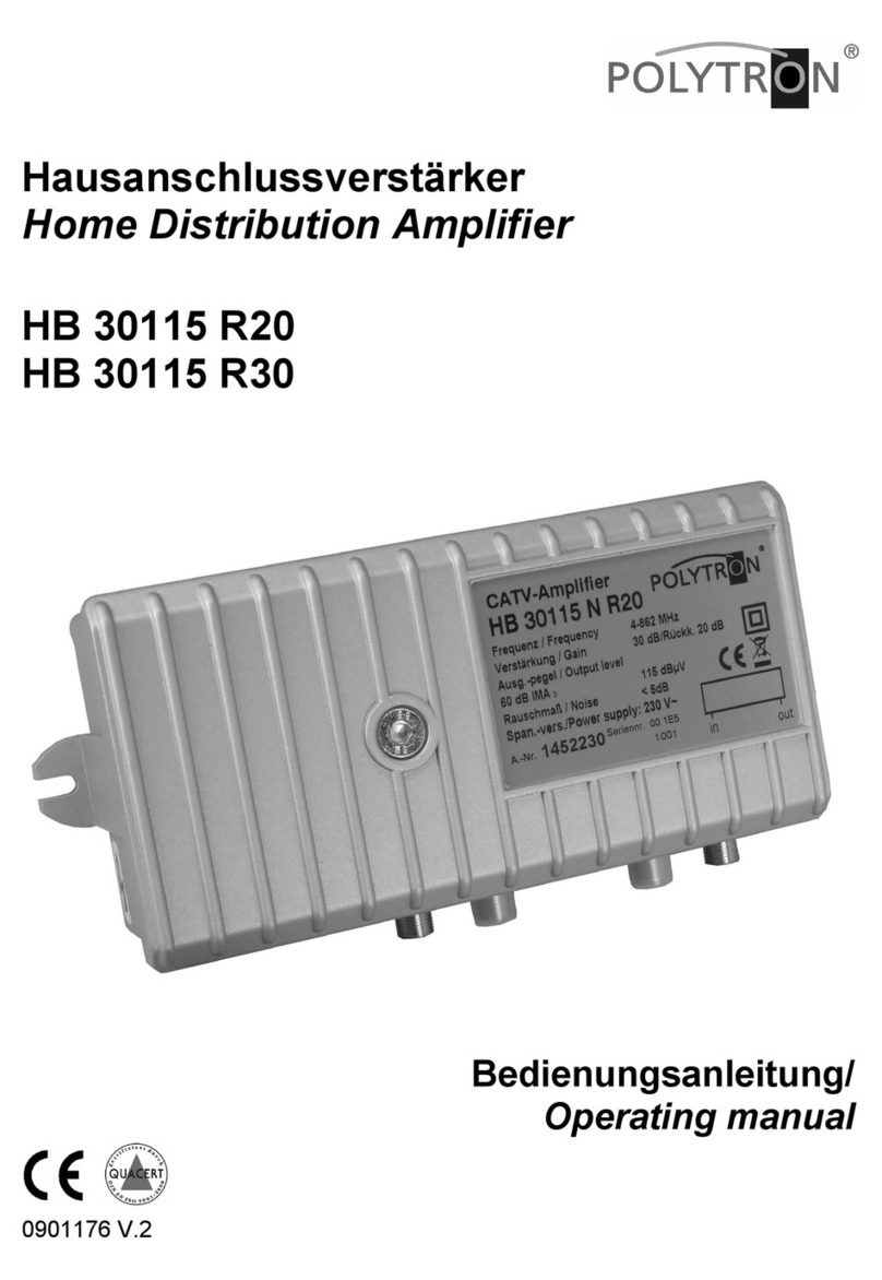
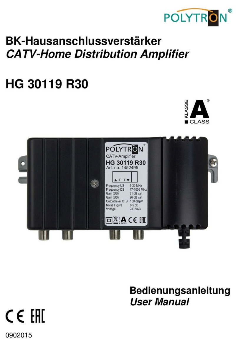
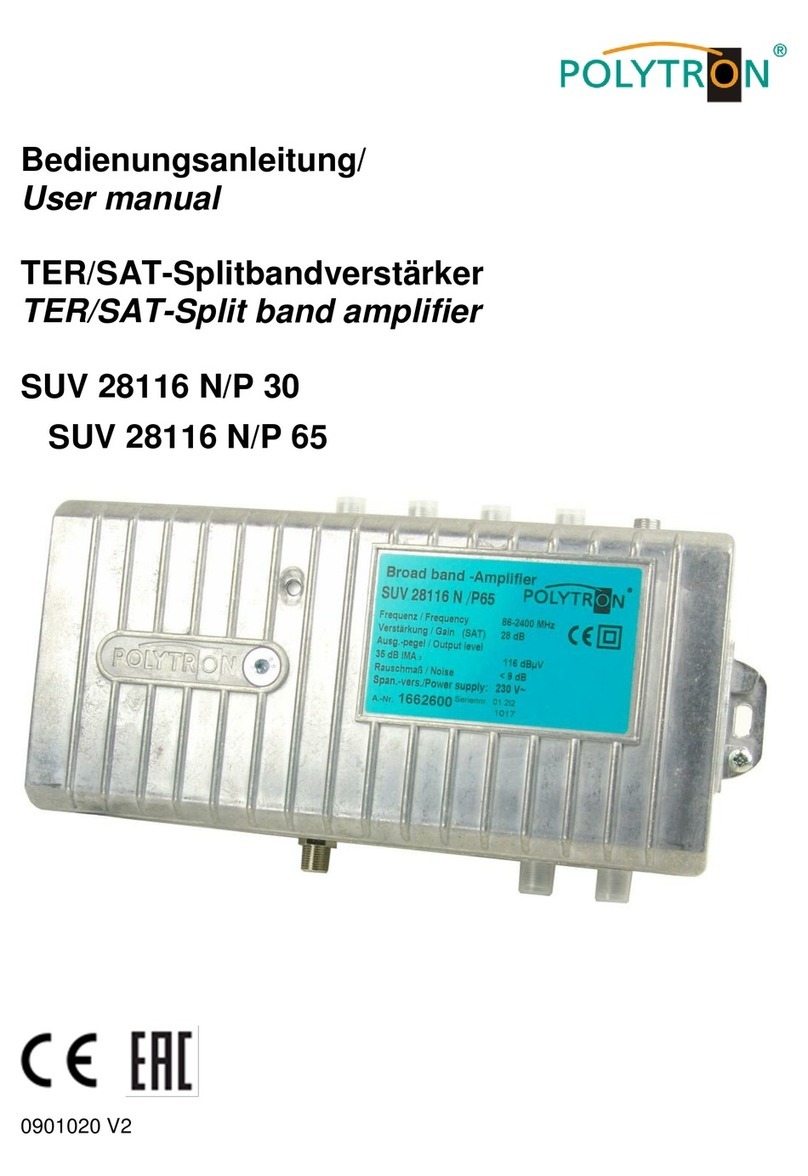
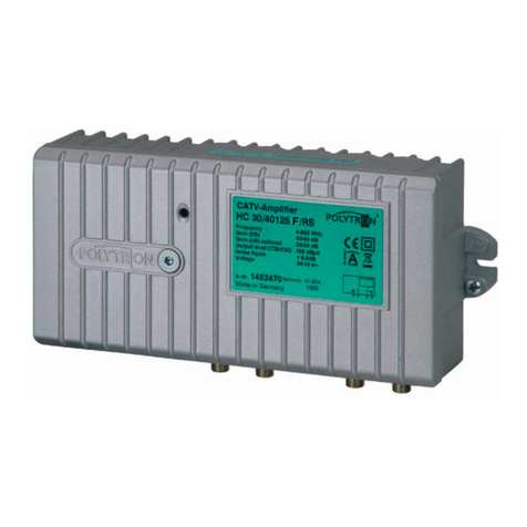
Table of contents
Languages:
Other Polytron Amplifier manuals

Polytron
Polytron CV 30 126 N/F User manual

Polytron
Polytron HC 30/40125 FRS User manual

Polytron
Polytron HG 30119 User manual

Polytron
Polytron HG 30119 R30 User manual

Polytron
Polytron HB 30115 R20 User manual

Polytron
Polytron SVV 36119 F User manual

Polytron
Polytron HG 30/40127D User manual

Polytron
Polytron HA 30116 N/AP User manual

Polytron
Polytron HG 40125 User manual

Polytron
Polytron SUV 28116 N/P 65 User manual