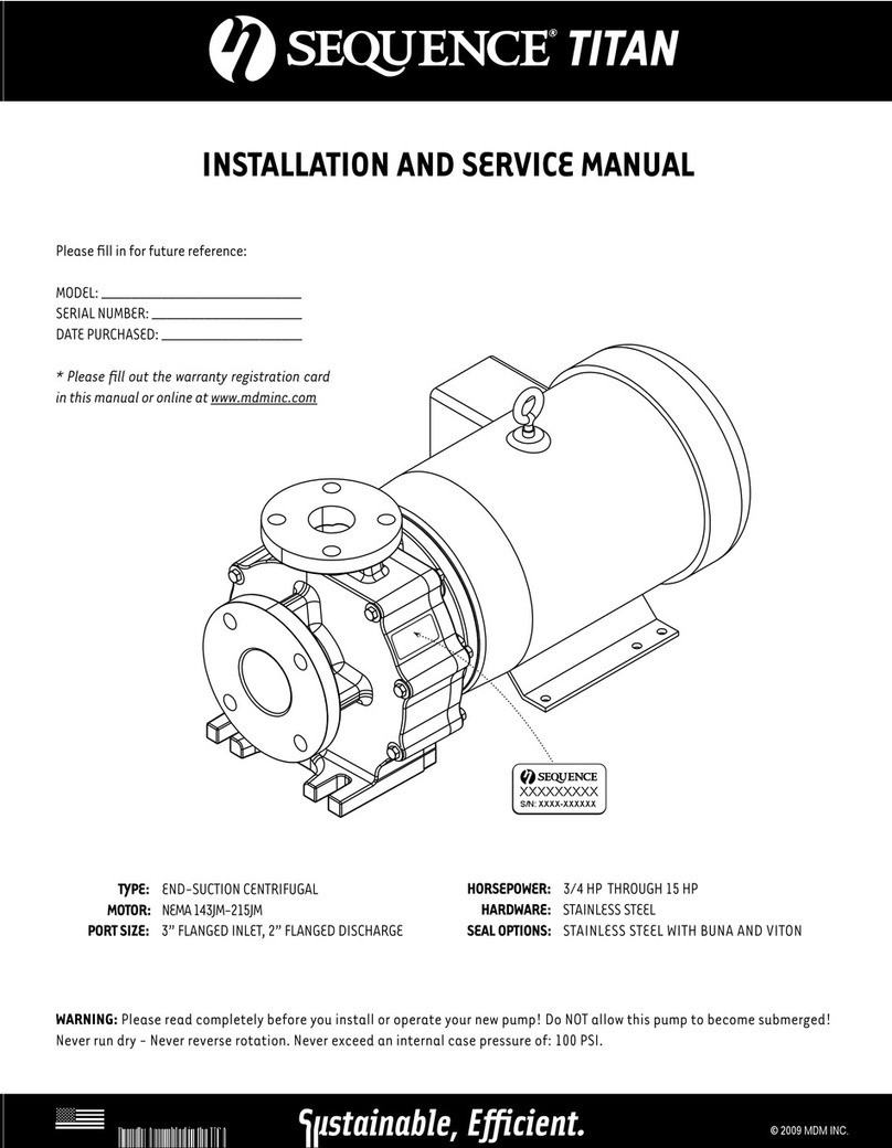
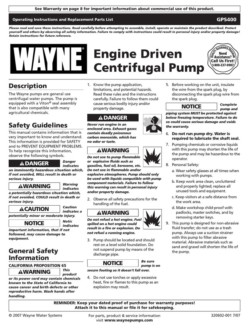
PompDirect ROBOT PUMPS RW Series Manual

782-001-GB HSC 08-W36 Edition 4
OPERAOPERA
OPERAOPERA
OPERATIONTION
TIONTION
TION
&&
&&
&
MAINTENMAINTEN
MAINTENMAINTEN
MAINTENANCE MANUANCE MANU
ANCE MANUANCE MANU
ANCE MANUALAL
ALAL
AL
RR
RR
RWW
WW
W-SERIES-SERIES
-SERIES-SERIES
-SERIES
www.robotpompen-onderdelen.nl
T +31(0)294-457712

Operation &
Maintenance Manual
Pump
RW
782-001-GB HSC 08-W36 Edition 4 3/32
Contents............................................................................................................................... page
1. FOREWORD................................................................................................................. 4
2. GUARANTEE ............................................................................................................... 4
3. SAFETY AND ENVIRONMENT.................................................................................... 5
3.1 Symbols ............................................................................................................................................... 5
3.2 General safety instructions .................................................................................................................. 5
3.3 Environment......................................................................................................................................... 5
4. TECHNICAL DATA....................................................................................................... 6
4.1 General ................................................................................................................................................ 6
4.2 Main parts ............................................................................................................................................ 6
5. FIRST PUMP START ................................................................................................... 9
5.1 Delivery check ..................................................................................................................................... 9
5.2 Oillevel ................................................................................................................................................. 9
5.3 Power supply........................................................................................................................................ 9
5.4 Thermoswitches ................................................................................................................................... 9
5.5 Cable entry........................................................................................................................................... 9
5.6 Motor protection ................................................................................................................................... 9
5.7 Motor check ......................................................................................................................................... 10
5.8 Installation parts ................................................................................................................................... 10
5.9 Direction of rotation.............................................................................................................................. 10
5.10 Current-check....................................................................................................................................... 10
5.11 Medium temperature / max. motorload................................................................................................ 11
5.12 Start frequency...................................................................................................................................... 11
5.13 Min. and max. submersible depth ........................................................................................................ 11
6. INSTALLATION OPTIONS ........................................................................................... 12
6.1 Installation -H ....................................................................................................................................... 12
6.2 Installation -V ....................................................................................................................................... 13
6.3 Checkpoint installation -V .................................................................................................................... 14
6.4 Installation -F ....................................................................................................................................... 15
6.5 Installation -T ....................................................................................................................................... 15
6.6 Installation -A ....................................................................................................................................... 16
6.7 Flange forcesand momentsforstationary immersiblepumps ............................................................... 16
7. MAINTENANCE............................................................................................................ 17
7.1 General ................................................................................................................................................ 17
7.2 Maintenanceschedule .......................................................................................................................... 17
7.3 Lubricants............................................................................................................................................. 17
7.4 Cable entry........................................................................................................................................... 18
7.5 Oil level................................................................................................................................................ 19
7.6 Oil change............................................................................................................................................ 20
7.7 Motor housing ...................................................................................................................................... 21
8. TRANSPORT AND STORAGE .................................................................................... 22
9. OPTIONS...................................................................................................................... 23
9.1 Waterdetector ...................................................................................................................................... 23
9.2 Thermoswitches ................................................................................................................................... 23
9.3 Thermistors .......................................................................................................................................... 23
9.4 Cable protection................................................................................................................................... 24
9.5 Special oil............................................................................................................................................. 24
9.6 Version with cooling system ................................................................................................................. 24
10. TROUBLE SHOOTING ................................................................................................ 25
APPENDIX 1; Dataplate....................................................................................................... 26
APPENDIX 2; Direct-on-line start motor............................................................................ 27
APPENDIX 3; Star-delta start motor................................................................................... 29
APPENDIX 4; Single phase start ........................................................................................ 31
APPENDIX 5; Notes............................................................................................................. 32
www.robotpompen-onderdelen.nl
T +31(0)294-457712

Operation &
Maintenance Manual Pump
RW
4/32 Edition 4 HSC 08-W36 782-001-GB
1. FOREWORD
You are to be congratulated on choosing a ROBOT
pump, which will undoubtedly serve you both reliably
and economically for a long time, providing you observe
the Maintenance Instructions given in this manual.
The RW-pump is a Non-Clogging Vortex pump designed
to pump sewage and other solids containing waste
water.
Properuse andmaintenancewillprolong theoperational
lifeof yourROBOTpump.
Thismanual containsdifferentwarningsand safety
precaution.
Readthis manualproperly,so thatdangerous situations,
physical injury or damage can be avoided.
TheRW-pumpis designedforprofessional
use only. Service and maintenance may only
bedone byauthorisedpersonnel,after
reading this manual.
The RW-pump in basic version may not be
used in a potentially explosive atmosphere.
When ordering spareparts, always quote.
1. Pump type
2. Code
3.Serial number
This information is found on the dataplate.
(See appendix 1)
Sectionaldrawings andpartslists areavailableon
request.
All products manufactured by ITTW&WWAlphen B.V.
aremade withgreat care andaccording toourhigh
internalstandards.Should youhoweverhaveany
suggestionsconcerning ourpumprange orthis
instruction manual which will contribute to the quality of
our product please do not hesitate to contact us.
ITT W&WWAlphen B.V.
Produktieweg 5
P.O. Box 140
2400 AC Alphen aan den Rijn
The Netherlands
2. GUARANTEE
Werefer tothewarranty agreementwithyour
local dealer.
www.robotpompen-onderdelen.nl
T +31(0)294-457712

Operation &
Maintenance Manual
Pump
RW
782-001-GB HSC 08-W36 Edition 4 5/32
3. SAFETY AND ENVIRONMENT
3.1 Symbols
* In this manual
General warning
Danger !
Electrical hazard !
Attention !
* On the pump
Danger of physical injury
Rotating parts !
Electrical hazard !
EC-conformity symbol
3.2 General safety instructions
* Onlytrained andauthorizedpersonal mayinstall and
maintain the pump after carefully reading this
manual.
* Only use the pump for its intended purposes and
under the regulated circumstances.
* Don’t go near rotating parts.
* Clean the pump before maintenance and inspection.
* Observe the local regulations when working with
agressive,corrossive, toxic, flammableandexplosive
chemicals.
* Never remove safety signs, keep them clean.
* Always connect to a grounded circuit.
* Before maintenance and inspection always
disconnect the pump from the mains.
* Use a proper hoist for lifting and handling the pump.
* Do not leave a large loop of cable in the sump,
as the pump may eventually damage it.
* Never drop the loose cable end in water. The water
may enter the cable and finally enter the
motorhousing, eventually causing motor failure.
3.3 Environment
Parts which are replaced during repair, maintenance or
renewal, could contain materials which could be harmful
to the environment.
Please take care in the disposal of these parts.
Do this in accordance with the local environmental
regulations.
www.robotpompen-onderdelen.nl
T +31(0)294-457712

Operation &
Maintenance Manual Pump
RW
6/32 Edition 4 HSC 08-W36 782-001-GB
4. TECHNICAL DATA
4.1 General
The RW-pump is a cast iron non-clogging vortex
impeller pump, designed to pump a wide variety of
solids contaminated liquids.
Thepump canbeused for sewageandother non-
agressivewaste water applications.
The impeller leaves a wide unobstructed passage
through the volute, in which a strong vortex is created
that carries most of the solids.
1 Pumpcasing
2 Impeller
3 Suction
4 Delivery
5 Motorcasing
6 Rotor
7 Stator
8 Shaft
9 Bearings
10 Mechanical seal
(2x)
11 Oil reservoir
12 Oil plug
13 Cable entry
14 Cable
15 Inspection plug
4.2 Main parts
Construction:
- High efficiency motor, standard class F
insulation (up to 155oC).
- Two independent mechanical seals, running in oil,
form an effective barrier between pump and motor.
- Heavyduty bearings, greasedforlife.
- Clog-free vortex impeller.
- Vanes at the backside prevent solids entering the
seal area and reduce the pressure on the seal.
13
14
11
OIL
9
10
12
2
4
15
6
7
9
1
3
Fig. 4.1
RW20
www.robotpompen-onderdelen.nl
T +31(0)294-457712

Operation &
Maintenance Manual
Pump
RW
782-001-GB HSC 08-W36 Edition 4 7/32
1 Pumpcasing
2 Impeller
3 Suction
4 Delivery
5 Motorcasing
6 Rotor
7 Stator
8 Shaft
9 Bearings
10 Mechanical seal
(2x)
11 Oil reservoir
12 Oil plug
13 Cable entry
14 Cable
15 Inspection plug
5
7
15
8
10
2
1
4
3
13
12
11
9
6
9
14
OIL
Fig. 4.2
RW40
RW60
Fig. 4.3
www.robotpompen-onderdelen.nl
T +31(0)294-457712

Operation &
Maintenance Manual Pump
RW
8/32 Edition 4 HSC 08-W36 782-001-GB
1 Pumpcasing
2 Impeller
3 Suction
4 Delivery
5 Motorcasing
6 Rotor
7 Stator
8 Shaft
9 Bearings
10 Mechanical seal
(2x)
11 Oil reservoir
12 Oil plug
13 Cable entry
14 Cable
15 Inspection plug
16 Cable entry box
15
15
14 32
5
OIL
7
6
9
9
10
10
8
14
13
11
12
16
Fig. 4.4
RW80
www.robotpompen-onderdelen.nl
T +31(0)294-457712

Operation &
Maintenance Manual
Pump
RW
782-001-GB HSC 08-W36 Edition 4 9/32
5. FIRST PUMSTART
After unpacking the pump, carry out the following check
points:
5.1 Delivery-check
Check for possible transport damage and especially
check that the cable has not been nicked or
damaged.
Check for complete delivery.
Whenthe deliveryisincomplete ordamaged,please
contactyour dealerimmediately.
5.2 Oil level
Check the oil level. (see 7.5)
5.3 Power supply
Before making the electrical connections, check if
the line voltage and frequency are the same as on the
pump dataplate.
If thermostats are supplied make sure that they are
correctly connected.
For examples of electrical diagrams and pump
cable coding, see appendix 2, 3 and 4.
5.4 Thermoswitches
Check if the pump is equipped with thermo-switches
(optional for RW20 and RW40, standard for RW60
series).
Contact rating: max. 250V-1.6A
The contacts are normally closed.
5.5 Cable entry
Especially when the pump has been in store for a
long time, the cable gland should be checked and
if necessary tightened (see 7.4).
5.6 Motor protection
The pump should always be connected to the line by
means of a suitable motor protection circuitbreaker.
If the pump is started direct on line (DOL), the protection
breaker should be set to the current, as given on the
dataplate.
For star delta start (YD), it is good practice to install the
overcurrent relay directly after the main contactor. In
this case, the pump is also adequately protected in star-
connection.The maximumsettingof theovercurrentrelay
is 0.6x the current as given on the dataplate.
It is good practice to set the protection breaker at a 10%
lower current, because all breakers require at least
110% of the adjusted current before tripping.
www.robotpompen-onderdelen.nl
T +31(0)294-457712

Operation &
Maintenance Manual Pump
RW
10/32 Edition 4 HSC 08-W36 782-001-GB
5.7 Motor check
If in doubt about the condition of the motor or cable,
Megger test motorwindings against grounding wire.
The phase resistance against grounding wire should be
at least 1 MOhm.
Turn the impeller clockwise by hand, using a proper
socket wrench (see fig.5.1)
This should be possible without much force.
With this procedure sticking mechanical seal
surfaces will be loosened smoothly.
5.8 Installation parts
Check if all components for your installation
are delivered. See also chapter 6.
5.9 Direction of rotation
A correct direction of rotation is essential for proper
operation. This can be checked as follows:
- Put the pump in horizontal position and start the
pump.
Looking on the impeller through the suction
opening, the correct direction of rotation is
counter-clockwise.
(See arrow on pumpcasing, Fig. 5.2).
or:
- Starting the pump will give a recoil on the
pump frame.
Looking at the motor (in vertical position see
Fig. 5.3), the recoil is counter-clockwise.
Take care !
The recoil can be very powerful !
Don’tgo nearrotating parts !
5.10 Current-check
Note the max. current from the dataplate.
Apply an ammeter to one of the phase wires
during normal operation. Check that the current
is not higher than the value on the dataplate.
(see appendix 1). If so check for:
- voltage (too low ?)
- specific gravity or viscosity of the fluid
(too high ?)
- blocked impeller ?
- direction of rotation correct ?
If the problem cannot be solved contact your dealer.
Fig. 5.1
Fig. 5.2
Fig. 5.3
www.robotpompen-onderdelen.nl
T +31(0)294-457712

Operation &
Maintenance Manual
Pump
RW
782-001-GB HSC 08-W36 Edition 4 11/32
5.11 Medium temp. / max.motorload
When the medium temperature is higher than 40oC, the
maximum motorload must be reduced.
The relationship between medium temperature and
maximum absorbed motor current is shown below.
Checkthe readingofthe dataplateagainstthe readingof
anAmmeter.
Ifthe motorcurrent exceedsthemax. motorcurrentfrom
the table below the pump is not suitable or the
motorcurrentmust bereduced.
The motorcurrent can be reduced by installing a
smaller impeller. Contact your dealer.
Temperature Max.motorcurrent
oCoF %
40 104 100
50 122 95
60 144 90
70 158 80
80 176 70
5.12 Start frequency
When the pump is controlled by level regulators, the on
and off levels should be adjusted in such a way, that the
pump does not do more than 20 starts an hour.
5.13 Min. and max. submersion depth
Themotorhousing shouldbeat least2/3submerged for
continuous operation at full load (see Hmin.1 Fig. 5.4).
It is good practice, whenever possible to keep the
motorhousing completely under water.
This is not applicable if the pump is
equipped with a cooling system.
For interrupted level controlled operation, less cooling is
required. We recommend not to run the pump with the
water level below the top of the volute in order to avoid
air being drawn in (see Hmin.2 Fig. 5.4).
Air in the discharge pipes might impair performance.
The maximum submersion depth is 20m / 60ft.
Fig. 5.4
www.robotpompen-onderdelen.nl
T +31(0)294-457712

Operation &
Maintenance Manual Pump
RW
12/32 Edition 4 HSC 08-W36 782-001-GB
6. INSTALLATION OPTIONS
For the submersible pump the following installations are
possible:
-H Stationary wet installation with a header coupling
type HK.
-V Stationary wet installation with a guide bar
quick release coupling type V.
-F Freestanding wet installation.
-T Transportable wet installation.
-A Stationary immersible installation.
6.1 INSTALLATION - H
Stationary wet installation with a ROBOT quick-release
header coupling type HK.
A flexible hose connects pump and coupling.
Most of the RW20 pumps (except types with a large
pumpcasing) will have a vertical position, see Fig. 6.1.
All RW 40 and RW60 pumps are horizontally placed,
see Fig. 6.2. Not available for RW80.
Except for the pump the following components are
necessary:
1. Hose connection, which is fastened to the
pump;
2. Flexible hose, between pump and coupling;
3. Header coupling, consisting of coupling
bend, rubber joint and a fixed coupling part;
4. Suspension bracket and chain, for lifting the
pump;
5. Level regulators for start-, stop- and alarm-
signals;
6. Suspension for level regulators and power
supply cable;
7. Piping, non return valve, bends etc.
Checkpoints before operating:
- Ensure a good free passage beneath
the suction elbow of the pump
(at least the same as the suction diameter).
- Adjust the start- and stoplevels in such a
way that the motor does not make more
than 20 starts per hour.
- Check that the motor is adequately cooled.
The motorhousing should be at least 2/3 submerged
for continuous operation at full load (see Hmin.1
Fig. 6.1).
It is good practice, whenever possible to keep the
motorhousing completely under water.
For interrupted level controlled operation, less cooling is
required. We recommend not to run the pump with the
water level below the top of the volute in order to avoid
air being drawn in (see Hmin.2 Fig. 6.1).
Air in the discharge pipes might impair performance.
Fig. 6.1
Fig. 6.2
www.robotpompen-onderdelen.nl
T +31(0)294-457712

Operation &
Maintenance Manual
Pump
RW
782-001-GB HSC 08-W36 Edition 4 13/32
6.2 INSTALLATION -V
Stationary wet installation with a ROBOT quick-release
guide bar coupling type -V. The pump is
automatically coupled to the discharge.
Except for the pump the following components are
necessary:
1. Bottom elbow, rubber joint and coupling
adapter;
2. Guide bar foundation plate
(n.a. for V-50 and V-65-S);
3. Two guide bars
(V-50 and 65-S coupling need only one guide bar);
4. Top bracket, mounted within the wellcover
clearance;
5. Level regulators for start-, stop- and alarm-
signals;
6. Suspension for level regulators and power
supply cables;
7. Piping, non return valve, discharge bends etc.
Checkpoints before operating:
- The guide bars must stand vertical
(maximum tolerance 3o).
- The installation angle should be :
RW20/RW40/RW60: 10-15o
RW80: 5o
(see Fig. 6.4). If necessary, this angle can be
changed by alteration of the position of the
lifting hook on the suspension bracket on top
of the motor (pos. 1).
- Adjust the start- and stoplevels in such a
way that the motor does not make more
than 20 starts per hour.
- Check that the motor is adequately cooled.
The motorhousing should be at least 2/3 submerged
for continuous operation at full load (see Hmin.1
Fig. 6.3).
It is good practice, whenever possible to keep the
motorhousing completely under water.
For interrupted level controlled operation, less cooling is
required. We recommend not to run the pump with the
water level below the top of the volute in order to avoid
air being drawn in (see Hmin.2 Fig. 6.3).
Air in the discharge pipes might impair performance.
Fig. 6.3
Fig. 6.4
www.robotpompen-onderdelen.nl
T +31(0)294-457712

Operation &
Maintenance Manual Pump
RW
14/32 Edition 4 HSC 08-W36 782-001-GB
6.3 Checkpoint installation - V
In some applications it is possible that the pump will not
work due to presence of air in the volute.
Lifting the pump a bit (10-20mm) while running may
solve the problem.
When the problem repeats, an air-venthole can be
drilled in the coupling adapter and a special gasket must
be fitted. (see fig. 6.5).
When air is present, this will escape through the hole.
When the fluid arrives, the special gasket will close the
hole.
- Take part (1) (fig.6.6).
- Drill a 8mm hole in the cast boss on top
ofthe coupling adapter.
- Deburr the hole.
- Place a special gasket (3) (Fig. 6.7)
- Mountthe couplingadapter (1)tothe
pump (2).
Part numbers for special gaskets.
Coupling type: part number:
V 65/ V 80 761-056
V 100 761-057
V 150 761-058
V 200-N 761-064
Fig. 6.5
Fig. 6.6
Fig. 6.7
Air
www.robotpompen-onderdelen.nl
T +31(0)294-457712

Operation &
Maintenance Manual
Pump
RW
782-001-GB HSC 08-W36 Edition 4 15/32
6.4 INSTALLATION - F
Freestanding: semi-permanent fixed wet installation.
Except for the pump the following components are
necessary:
1. Hose or threaded connection, which is
fastened to the pump;
2. Flexible hose or pipe;
3. Pump support;
4. Level regulators.
Checkpoints before operating:
- Adjust the start- and stoplevels in such a
way that the motor does not make more
than 20 starts per hour.
- Check that the motor is adequately cooled.
The motorhousing should be at least 2/3 submerged
for continuous operation at full load (see Hmin.1
Fig. 6.8).
It is good practice, whenever possible to keep the
motorhousing completely under water.
For interrupted level controlled operation, less cooling
is required. We recommend not to run the pump with
the water level below the top of the volute in order to
avoid air being drawn in (see Hmin.2 Fig. 6.8).
Air in the discharge pipes might impair performance.
6.5 INSTALLATION - T
Transportable wet installation.
Except for the pump the following components are
necessary:
1. Hose connection, which is fastened to the pump;
2. Flexible hose;
3. Pump support.
Checkpoints before operating:
- Do not let the pump bury itself in the mud.
- Do not leave a large loop of the cable in
the sump, as the pump may eventually
damage it.
- Check that the motor is adequately cooled.
The motorhousing should be at least 2/3 submerged
for continuous operation at full load (see Hmin.1
Fig. 6.9).
It is good practice, whenever possible to keep the
motorhousing completely under water.
For interrupted level controlled operation, less cooling
is required. We recommend not to run the pump with
the water level below the top of the volute in order to
avoid air being drawn in (see Hmin.2 Fig. 6.9).
Air in the discharge pipes might impair performance.
Fig. 6.8
Fig. 6.9
www.robotpompen-onderdelen.nl
T +31(0)294-457712

Operation &
Maintenance Manual Pump
RW
16/32 Edition 4 HSC 08-W36 782-001-GB
6.6 Installation - A
Stationary immersible installation, horizontal, see fig. 6.10
orvertical, seefig. 6.11.
This installation is only possible if the pump is equipped
with a cooling system.
The main components are :
1. pumpcasing
2. motorunit
3. cooling system
4. sealhousing
5. pump support
6. discharge pipeline
7. suction pipeline
8. levelregulators for start-stop- and alarm-signals
Checkpoints before operating:
- In-lineposition ofthedischarge andsuction
pumpflanges.
- Forces on the pumpflanges may not exceed
the values in par. 6.7.
- Adjust the start- and stoplevels in such a
way that the motor does not make more
than 20 starts per hour.
If maintenance and/or inspection is necessary, as
described in chapter 7, we recommend to disconnect the
motorunitfrom thepumpcasing.
This can easily be done by removing the nuts of the
sealhousing-pumpcasing connection.
6.7 Flange forces and moments for
stationary immersible pumps
Because of the pipeline system, specific forces on the
discharge and suction flanges of the pump will occur:
The forces (F) and moments (M) may not exceed the
values of table below.
1. Forces Fx, Fy and Fz
2. Moments Mxy, Mxz and Myz
See fig. 6.12
(1) is the discharge flange
(2) is the suction flange
Pump Fx Fy Fz Mxy Mxz Myz
type [N] [N] [N] [Nm] [Nm] [Nm]
RW60 1200 1200 2500 1000 1000 1100
RW80 1200 1200 2800 1100 1100 1200
Fig. 6.10
Fig. 6.11
Fig. 6.12
www.robotpompen-onderdelen.nl
T +31(0)294-457712

Operation &
Maintenance Manual
Pump
RW
782-001-GB HSC 08-W36 Edition 4 17/32
7. MAINTENANCE
7.1 General
Always disconnect the pump from the
mains before inspection or disassembly.
Clean the pump thoroughly.
The motor housing can be hot when the
pump is just switched off.
7.2 Maintenance schedule
* After the first 20 running hours:
- Check the oil level (see chapter 7.5).
If there is more than a few drops of water
in it, contact your dealer.
* Every 6 months or 500 running hours:
- Check the oil and oil level (see chapter 7.5).
If there is more than a few cm3 water in it,
contact your dealer.
- Refresh the oil every year or when it is no
longertransparent. (seechapter7.6)
- RW80:refresh thegreaseofthe mainbearingevery
10,000runninghours.
7.3 Lubricants
* The bearings are greased for life and need
norefill (exceptRW80).
Main bearing RW80: SHELLALBIDA EP 2.
* The oil reservoir is filled with SHELL
VITREA ISO-VG 46 .
Viscosity: 46 cSt.
When another kind of oil is used this is
marked on a label on the pump.
Oil quantities:
RW 20: 0.6 L
RW 40: 1.5 L
RW 60: 2.4 L
RW 80: 7.3 L
www.robotpompen-onderdelen.nl
T +31(0)294-457712

Operation &
Maintenance Manual Pump
RW
18/32 Edition 4 HSC 08-W36 782-001-GB
7.4 Cable entry
Especially when the pump has been in use for a long
time, the compression of the rubber cable
seal might be deminished, which can cause leakage. By
screwing-in the cable entry the seal will be retentioned.
7.4.1 RW 20
Turn the hexagon head of the entry (1) for 1/6 of a turn
clockwise using the right tool.
It is possible that your cable entry is
fitted with a cable clamp.
See 7.4.2.
7.4.2 RW 40
Unscrew the 2 hexagon socket screws (1).
Remove the cable clamp (2).
Turn the hexagon head of the entry (1) clockwise, using
the right tool, so far that it is possible to replace the
cable clamp again.
Screw-in the 2 hexagon socket screws (1).
It is possible that your pump is fitted
with 2 cable entries.
7.4.3 RW 60 / RW 80
Unscrew the 4 hexagon socket screws (1) from
the outer cable entries.
Remove the cable clamps (2).
Turn the hexagon heads of the entry clockwise,
using the right tool, so far that it is possible to
replace the cable clamps again.
Screw in the 4 hexagon socket screws (1).
Turn the hexagon head of the middle entry (3) for 1/6 of
a turn clockwise.
It is possible that your pump is fitted
with only 2 cables.
Fig. 7.1
Fig. 7.2
Fig. 7.3
www.robotpompen-onderdelen.nl
T +31(0)294-457712

Operation &
Maintenance Manual
Pump
RW
782-001-GB HSC 08-W36 Edition 4 19/32
7.5 Oil level
7.5.1 RW 20
Put the pump in a horizontal position so that the 2
hexagonal socket screws are on top (see fig.7.4).
Unscrew the level plug (1) and the vent plug (2).
Theoil levelshould beatthe lowerside oftheopenings
(see drawing).
By turning the pump a bit this should be visible.
If not so fill up to the right level.
Always use the right kind of oil !
It is possible that your pump is fitted
with 3 plugs.
For oil check see 7.5.2
7.5.2 RW 40
Put the pump in a horizontal position so that 2
hexagonal socket screws are on top and one at
the bottom (see fig.7.5).
Unscrew the level plug (1) and the vent plug (2).
Theoil levelshould beatthe lowerside oftheopenings
(see drawing). By turning the pump a bit this should be
visible.
If not so fill up to the right level.
Always use the right kind of oil !
7.5.3 RW 60 / RW 80
Put the pump in a vertical position.
Unscrew the M20 oil pug (1) which can be found at the
opposite side of the cable entry box
(see fig. 7.6).
The oil level should be at the lower side of the opening.
If not so fill up to the right level.
Always use the right kind of oil !
Ensure that the pump is fully supported
to prevent it from falling over !
Fig. 7.4
Fig. 7.5
Fig. 7.6
www.robotpompen-onderdelen.nl
T +31(0)294-457712

Operation &
Maintenance Manual Pump
RW
20/32 Edition 4 HSC 08-W36 782-001-GB
7.6 Oil change
Collection, storage and removal of the
oil should be done according to the
regulations of the local authorities.
When necessary replace the sealing rings.
Always use the right kind of oil !
(see chapter 7.3).
7.6.1 RW 20
Put the pump in a horizontal position so that one of oil
plugs is at the bottom ( fig.7.7 position B).
Remove the vent plug (2).
Put a receiving bin underneath the drain plug (1).
Remove the plug and drain the oil.
Rotate the pump so that the 2 openings are on top
(fig.7.7 position C).
Refill the oilhousing.
The oil level should be at the lower side of the openings.
(fig.7.7 position A).
Replace the plugs.
7.6.2 RW 40
Put the pump in a horizontal position so that the drain
plug (3) is at the bottom (Fig.7.8 position A).
Remove the vent plugs (1) and (2).
Put a receiving bin underneath the drain plug.
Remove the plug and drain the oil.
Replace the drain plug.
Refill the oilhousing.
The oil level should be at the lower side of the openings
(Fig.7.8 position A).
Replace the plugs.
7.6.3 RW 60 / RW 80
Put the pump in a horizontal position so that the drain
plug (M20) is at the bottom (Fig.7.9 pos. A).
Remove the vent plugs (1) and (2).
Put a receiving bin underneath the drain plug.
Remove the plug and drain the oil.
Replace the drain plug (3).
Refill the oilhousing through the opening (1).
The oil level should be at the lower side of the
opening (Fig.7.9 position A).
Replace the plugs.
Fig. 7.7
Fig. 7.8
Fig. 7.9
www.robotpompen-onderdelen.nl
T +31(0)294-457712

Operation &
Maintenance Manual
Pump
RW
782-001-GB HSC 08-W36 Edition 4 21/32
7.7 Motor housing
7.7.1 RW 20
Unscrew the inspection plug of the motorhousing (see
Fig. 7.10 pos 1).
Put the pump in horizontal position with the inspection
openingdownwards.
If water is present this will come out this way.
A small amount of water, due to condensation, is
permissable.
More water is an indication of leakage of
the construction. Oil is an indication of
seal failure between motorhousing and oil
chamber. If so, contact your dealer.
7.7.2 RW 40
Unscrew the inspection plug of the motorhousing.
This plug is found at the opposite side of the cable
entries (see Fig.7.11 pos 1).
Put the pump in horizontal position with the inspection
opening downwards. If water is present this will come
out this way.
A small amount of water, due to condensation, is
permissable.
More water is an indication of leakage of the
construction. Oil is an indication of
sealfailure between motorhousingandoil
chamber. Ifso,contact yourdealer.
7.7.3 RW 60
Place the pump in a vertical position and remove the 4
hexagon socket screws (1) of the cable entry box (2).
Pull the cable entry box a few cm’s from the pump.
If water is present this will come out this way.
A small amount of water, due to condensation, is
permissable.
Morewater isan indicationofleakage of
the construction. Oil is an indication of
sealfailure between motorhousingandoil
chamber. Ifso,contact yourdealer.
Fig. 7.10
Fig. 7.11
Fig. 7.12
www.robotpompen-onderdelen.nl
T +31(0)294-457712
This manual suits for next models
4
Table of contents
Popular Power Pump manuals by other brands
BLACKMER
BLACKMER GX Series Operation and maintenance
Wayne
Wayne WEU250 operating instructions
ProMinent
ProMinent Makro TZ operating instructions
BLACKMER
BLACKMER SX3A Installation, operation and maintenance instructions
Greenlee
Greenlee 940m3 SERIES instruction manual
Patterson
Patterson RC Operation and maintenance manual
