Greenlee Textron / Subsidiary of Textron Inc. 94455 Boeing Dr., Rockford, IL 61109-2988 815/397-7070
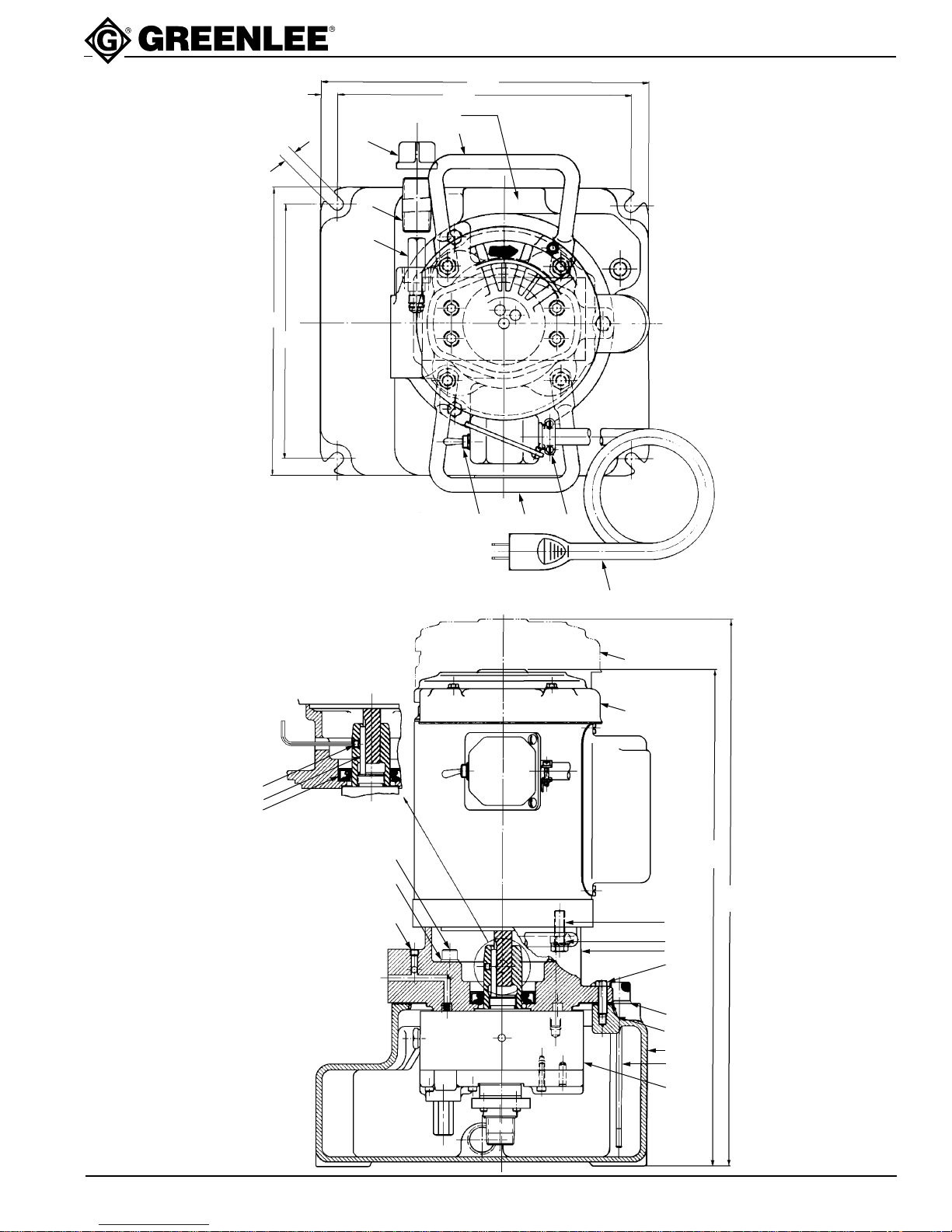
1721-M4 Basic & 1722-M4 Basic Hydraulic Power Pumps
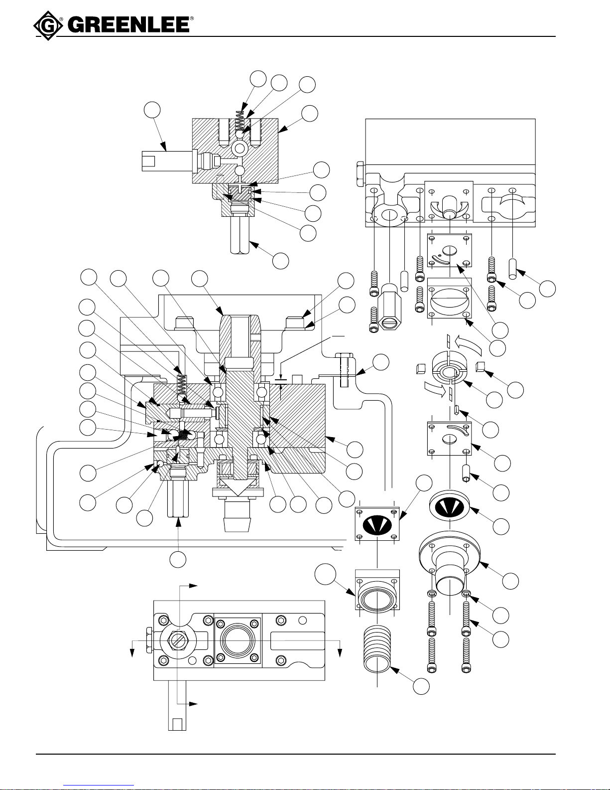
Parts - Hydraulic Power Pumps
1721-M4 Basic (501 8320.6)
1722-M4 Basic (501 8355.9)
Key Control No. Description Qty
A 501 8236.6 Block Unit, Pump (1 - 41) ...................................................................... 1
1 500 6067.8 Valve Unit, Relief ................................................................................... 1
2 501 7766.4 Valve Unit, Relief ................................................................................... 1
3 501 8194.7 Plate, Pump Mounting ........................................................................... 1
4 500 3493.6 Pin, Seal ................................................................................................ 1
5 501 8871.2 Spacer, Bearing..................................................................................... 1
6 501 1855.2 Race, Outer ........................................................................................... 1
7 501 1862.5 Plug, Hi-Pressure Plunger ..................................................................... 1
8 501 9060.1 Plunger, Hi-Pressure ............................................................................. 1
9 501 9059.8 Bushing, Hi-Pressure Plunger ............................................................... 1
10 502 0424.6 Block, Intake .......................................................................................... 1
10A 501 4859.1 Block, Intake (replaced by 10)............................................................... 1
11 501 4861.3 Plate, Pump ........................................................................................... 1
12 501 4862.1 Key, Lo-Pressure Pump ........................................................................ 1
13 501 4876.1 Shaft, Eccentric...................................................................................... 1
14 501 7130.5 Plate, Top .............................................................................................. 1
15 501 7131.3 Plate, Bottom ......................................................................................... 1
16 501 7135.6 Vane....................................................................................................... 4
17 501 7136.4 Rotor ...................................................................................................... 1
18 501 7467.3 Dowel, Hollow ........................................................................................ 1
19 501 8195.5 Plunger, Check Valve ............................................................................ 1
20 501 8237.4 Block, Pump........................................................................................... 1
21 501 8238.2 Adapter, Drive Shaft .............................................................................. 1
22 500 6111.9 Spring, Compression ............................................................................. 1
23 501 4865.6 Spring, Compression ............................................................................. 1
24 502 1175.7 Screen, Intake........................................................................................ 1
24A 501 6599.2 Screen, Intake (replaced by 24) ............................................................ 1
25 905 0014.8 O-Ring, 5/8 x 3/4 x 1/16......................................................................... 1
26 905 0436.4 Ball, 9/32 Grade #1 Chrome Steel ........................................................ 2
27 905 0490.9 Nipple, Intake (replaced by 10) ............................................................. 1
28 905 0677.4 Ball, 5/32 Grade #1 Chrome Steel ........................................................ 1
29 905 0681.2 Ball, 3/8 Grade #1 Chrome Steel .......................................................... 1
30 905 1526.9 Washer, #8 Hi-Collar Lock..................................................................... 4
32 905 0911.0 Roller, .125 x .750 ............................................................................... 30
33 905 1524.2 O-Ring, 1/2 x 5/8 x 1/16......................................................................... 1
34 905 0989.7 Bearing, Single Row Unshielded Ball.................................................... 1
35 905 0994.3 Screw, #8-32 NF x 1-1/4 Socket Head Cap .......................................... 4
36 905 1111.5 Screw, 7/16-20 NF x 1/2 Cup Point Socket Set .................................... 1
37 905 2817.4 O-Ring, 7/16 x 9/16 x 1/16..................................................................... 1
38 905 1241.3 Screw, #10-32 NF x 3/16 Flat Point Socket Set.................................... 1
39 905 1471.8 Screw, #10-32 NF x 7/8 Socket Head Set Cap ..................................... 6
40 905 1472.6 Lok-Dowel, 1/4 x 3/4.............................................................................. 2
41 905 1473.4 Bearing, Single Row Unshielded Ball.................................................... 1
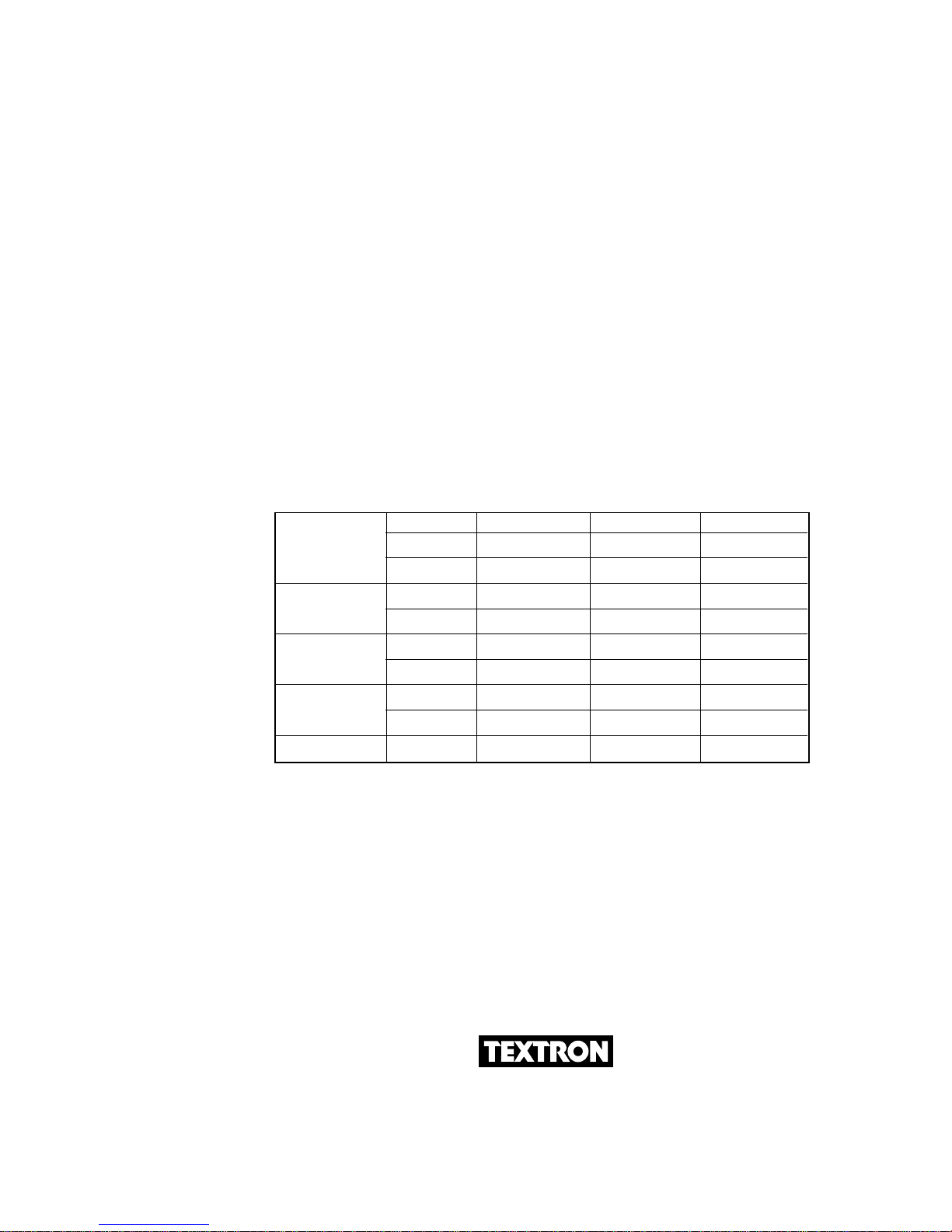
52 500 3407.3 Valve Unit, Relief ................................................................................... 1
53 501 5646.2 Dipstick Unit........................................................................................... 1
54 503 2705.4 Plate, Motor Mounting ........................................................................... 1
55 501 5695.0 Reservoir ............................................................................................... 1
56 501 2663.6 Handle, Lifting........................................................................................ 2
57 501 4852.4 Key......................................................................................................... 1
58 501 5701.9 Gasket Reservoir ................................................................................... 1
59 905 0320.1 Seal, 1-3/8 ID x 2-3/8 OD Oil................................................................. 1
60 905 0467.4 Cap, 3/4 Pipe ......................................................................................... 1