Viking pump SLAL Operating manual

SL SERIES PUMP WITH HEAD REMOVED
SL SERIES PUMP CUTAWAY
TECHNICAL SERVICE MANUAL
VIKING PUMP, INC. •A Unit of IDEX Corporation • Cedar Falls, IA 50613 USA
SECTION TSM 288
PAGE 1 OF 36
ISSUE A
CONTENTS
1.0 Safety Information...................................................2
1.1 Risk Assessment Relating to the Use of Viking
Pump Classic+ Rotary Lobe Pumps and Pump
Units in Potentially Explosive Atmospheres ............3
2.0 Introduction .............................................................3
2.1 General ...................................................................3
2.2 Viking Pump Distributors.........................................3
2.3 Receipts and Storage..............................................3
2.4 Cleaning..................................................................3
2.5 Pump Model Designation........................................4
2.6 Atex Information Plate.............................................4
2.6.1 Equipment Groups & Categories ............................4
2.7 Pump Model and Serial Number.............................4
2.8 Standard Pump Component Terms.........................5
3.0 General ...................................................................5
3.1 SL Pumping Principle..............................................5
3.2 Rotary Lobe Pump Principle ...................................5
3.3 SL Pump Operating Parameters .............................5
3.4 System Design and Installation...............................6
3.4.1 Installation For In-Line Cleaning Systems...............7
3.5 Start Up Procedure .................................................7
3.6 Shutdown Procedure...............................................8
3.7 Routine Maintenance ..............................................8
3.8 Integral Pressure Relief Valves ...............................8
3.8.1 Setting and Operating Spring Loaded Valves .........8
3.8.2 Setting and Operating Air Loaded Valve .................9
3.9 Rectangular Inlet...................................................11
3.9.1 Jacketed Head ......................................................11
3.9.2 Jacketed Casing....................................................12
4.0 SL Pump Dismantling and Assembly ....................12
4.1 Pump Assembly SLA – SLF ..................................13
4.1.1 Shaft Assembly .....................................................13
4.1.2 Rolling Torque / Pre-load.......................................14
4.1.3 Casing Assembly...................................................14
4.1.4 Rotor Assembly.....................................................15
4.1.5 Setting Front Clearances SLA – SLD....................15
4.1.6 Setting Front Clearance SLE and SLF..................15
4.1.7 Foot Assembly.......................................................16
4.1.8 Timing – Multilobe Rotors Only .............................16
4.1.9 Gearbox Assembly................................................17
4.1.10 Final Assembly......................................................17
4.2 Pump Assembly SLG ............................................18
4.2.1 Shaft Assembly .....................................................18
4.2.2 Rolling Torque / Pre-load.......................................19
4.2.3 Final Pre-load Assembly .......................................19
4.2.4 Timing – Multilobe Rotors only..............................19
4.2.5 Foot Assembly.......................................................20
4.2.6 Setting Front Clearance SLG................................21
4.2.7 Final Assembly......................................................21
4.2.8 Gearbox Assembly................................................22
5.0 Seals .....................................................................23
5.1 Single Seal SLA – SLG .........................................23
5.2 Single Flush SLA – SLF ........................................24
5.3 Single Flush SLG ..................................................26
5.4 Double Seal SLA, SLB, SLC.................................27
5.5 Double Seal SLD – SLG .......................................29
5.6 Rotary Seal Removal ............................................30
6.0 Specications........................................................31
6.1 Clearance Chart....................................................31
6.2 Fasteners & Torque Settings.................................32
6.3 Lip-Seal Setting Distances....................................33
6.4 Lubricants..............................................................33
6.5 Material Specication............................................33
6.6 Trouble Shooting...................................................33
6.7 SL Series Foundation Dimensions........................34
6.8 Tool List.................................................................35
SL SERIES ROTARY LOBE PUMPS
MODELS SLAS, SLAL, SLBS, SLBL, SLCS, SLCL,
SLDS, SLDL, SLES, SLEL, SLFS, SLFL, SLGS, SLGL

SECTION TSM 288 ISSUE A PAGE 2 OF 36
DO NOT OPERATE PUMP IF:
- The head is not installed correctly.
- Any guards are missing or incorrectly installed.
- The suction or discharge piping is not connected.
DO NOT place ngers, etc. into the pumping chamber
or its connection ports or into any part of the gearbox if
there is ANY possibility of the pump shafts being rotated.
Severe injury will occur.
DO NOT exceed the pumps rated pressure, speed, and
temperature, or change the system/duty parameters
from those for which the pump was originally supplied,
without conrming its suitability for the new duty. Running
the pump outside of its operating envelope can cause
mechanical contact in the pump head, excessive heat
and can represent a serious risk to health and safety.
Installation and operation of the pump must always
comply with health and safety regulations.
A device must be incorporated into the pump, system,
or drive to prevent the pump exceeding its stated duty
pressure. It must be suitable for both directions of pump
rotation where applicable. Do not allow pump to operate
with a closed/blocked discharge unless a pressure
relief device is incorporated. If an integral relief valve is
incorporated into the pump, do not allow re-circulation
through the relief valve for extended periods, refer to
section 3.8
The mounting of the pump or pump unit should be solid
and stable. Pump orientation must be considered in
relation to drainage requirements. Once mounted, shaft
drive elements must be checked for correct alignment.
Rotate pump shaft by at least one full revolution to ensure
smoothness of operation. Incorrect alignment will produce
excessive loading and will create high temperatures and
increased noise emissions. It may also be necessary to
earth the pump to avoid the build up of a potential charge
difference that could cause a spark.
The installation must allow safe routine maintenance and
inspection (to check for leakage, monitor pressures, etc)
and provide adequate ventilation necessary to prevent
overheating.
SL series pumps are shipped fully lubricated with a lithium
based extreme pressure Grease suitable for sealed for
life units.
Before operating the pump, be sure that it and all parts
of the system to which it is connected are clean and
free from debris and that all valves in the suction and
discharge pipelines are fully opened. Ensure that all piping
connecting to the pump is fully supported and correctly
aligned with its relevant connections. Misalignment
and/or excess loads will cause severe pump damage.
This could result in unexpected mechanical contact in
the pump head and has the potential to be a source of
ignition.
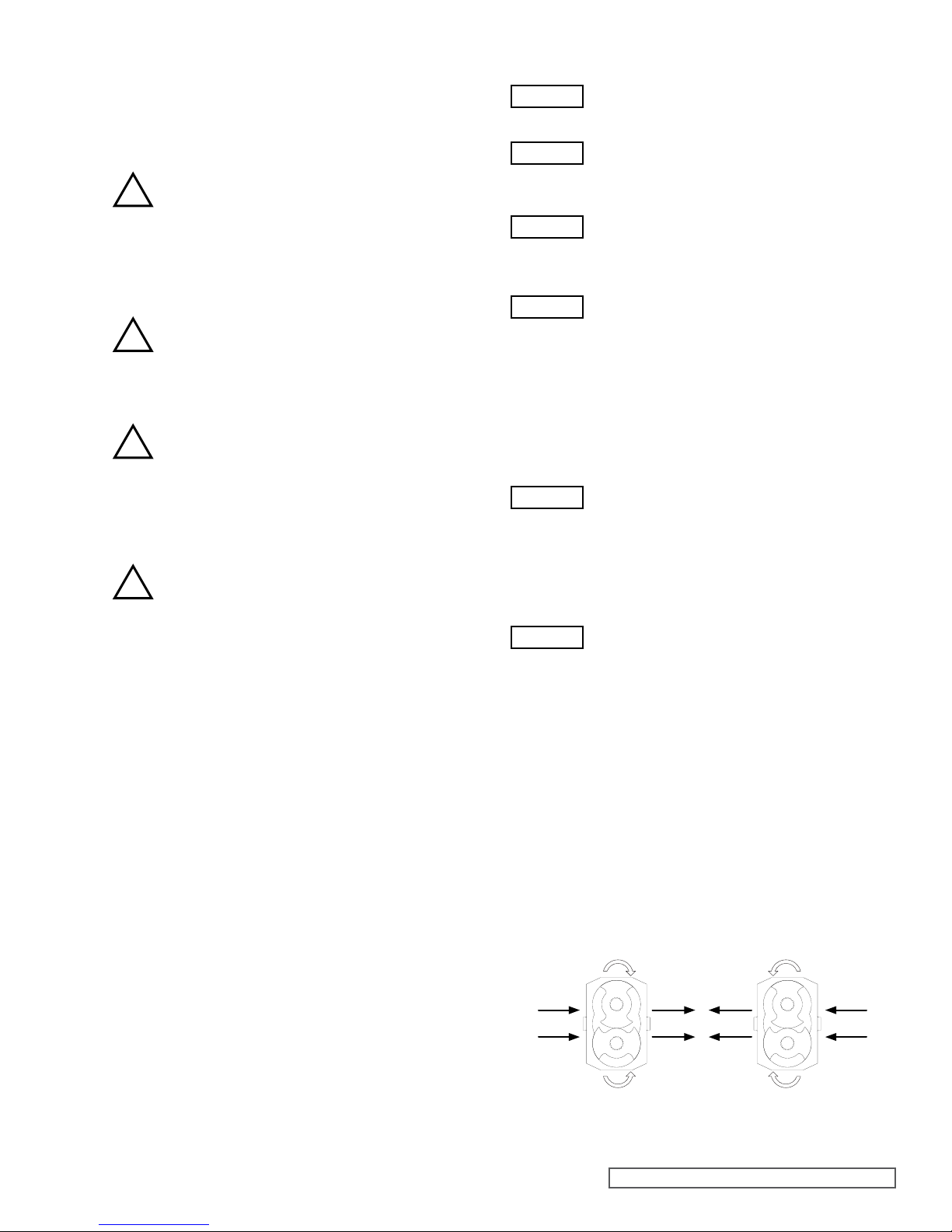
Be sure that pump rotation is correct for the desired
direction of ow (refer to section 3.1).
Do not install the pump into a system where it will run
dry (i.e. without a supply of pumped media) unless it is
equipped with a ushed shaft seal arrangement complete
with a fully operational ushing system. Mechanical seals
require a thin uid lm to lubricate the seal faces. Dry
running can cause excessive heat and seal failure.
Pressure gauges/sensors are recommended, next to
the pump suction and discharge connections to monitor
pressures.
Caution must be taken when lifting the pump. Suitable
lifting devices should be used as appropriate. Lifting eyes
installed on the pump must only be used to lift the pump,
not pump with drive and/or base plate. If pump is base
plate mounted, the base plate must be used for all lifting
purposes. If slings are used for lifting, they must be safely
and securely attached.
DO NOT attempt any maintenance or disassembly of the
pump or pump unit without rst ensuring that:
- The pump is fully isolated from the power source
(electric, hydraulic, pneumatic).
- The pumping chamber, pneumatic relief valve and
any shaft seal support system are depressurized and
purged.
- Any temperature control devices (jackets, heat-tracing,
etc) are fully isolated, that they are depressurized and
purged, and components are allowed to reach a safe
handling temperature.
DO NOT attempt to dismantle a pressure relief valve,
which has not had the spring pressure relieved, is still
connected to a pressurized gas/air supply or is mounted
on a pump that is operating. Serious personal injury or
death and/or pump damage may occur.
DO NOT loosen or undo the head, any connections to the
pump, shaft seal housings, temperature control devices,
or other components, until sure that such action will not
allow the unsafe escape of any pressurized media.
Pumps and/or drives can produce sound power levels
exceeding 85dB (A) under certain operating conditions.
When necessary, personal protection against noise must
be taken
Avoid any contact with hot parts of pumps and/or drives
that may cause injury. Certain operating conditions,
temperature control devices (jackets, heat-tracing, etc.),
bad installation, or poor maintenance can all promote
high temperatures on pumps and/or drives.
When cleaning, either manually or by an in-line cleaning
method, the operator must ensure that a suitable
procedure is used in accordance with the system
requirements. During a in-line cleaning cycle, a pump
differential pressure of between 2 and 3 bar (30 and 45
psi) is recommended to ensure suitable velocities are
reached within the pump head. The exterior of the pump
should be cleaned periodically.
Surface temperature of pump is also dependent on the
temperature of pumped medium.
1.0 SAFETY INFORMATION
Danger - Failure to follow the listed
precautionary measures identified by
this symbol may result in serious injury
or death.
Warning - Safety instructions which
shall be considered for reasons of safe
operation of the pump or pump unit and/
or protection of the pump or pump unit
itself are marked by this symbol.
INCORRECT INSTALLATION, OPERATION OR MAINTENANCE OF EQUIPMENT MAY CAUSE SEVERE
PERSONAL INJURY OR DEATH AND/OR EQUIPMENT DAMAGE AND MAY INVALIDATE THE WARRANTY.
This information must be read fully before beginning installation, operation or maintenance and must be
kept with the pump. All installation and maintenance must be undertaken by suitably trained or qualified
persons only.
Symbol
Legend :
!
!
!
!
!
!
!
!
!
!
!
!
!
!
WARNING
WARNING
WARNING
WARNING
WARNING
WARNING
WARNING
WARNING

SECTION TSM 288 ISSUE A PAGE 3 OF 36
Source
of Hazards
Potential
Hazards
Frequency
of Hazards
Recommended
Measures
Unvented
Cavities Build up of explosive gas Very Rare
Ensure that pump is totally
lled. Consider mounting
ports vertically.
Casing /
Rotors /
Head
Unintended mechanical
contact Rare
Ensure that operating
pressures are not
exceeded. Ensure that
sufcient NPSH to prevent
cavitation. Service Plan.
Pump
External
Surfaces
Excess temperature.
Electrostatic charging Rare
User must ensure
temperature limits. Do not
overll gearboxes with
lubricant. Provide a ground
contact for pump.
Service plan.
Cover
O-Ring
Pump liquid leakage.
Build up of explosive gas Very Rare
Check selection of
elastomers are suitable for
application. Ensure cover
retaining nuts are tight.
Service plan.
Pump
Casing / Cover
Pump liquid leakage.
Build up of explosive gas Very Rare Stainless Steel.
Corrosion Resistant.
Shaft Seals
Excessive temperature.
Unintended mechanical
contact. Leakage. Build
up of explosive gas
Rare
Selection of seal system
must be suitable for
application. Manual.
Service plan. Seals must
never run dry.
Auxiliary
System for
Shaft
Sealing
Pump liquid leakage.
Build up of explosive gas Rare
Selection of auxiliary seal
system must be suitable
for application. Seals must
never run dry.
Rotation
Direction
Test
Excess Temperature Very Rare
If ushed seals are
installed, ensure that
ush is applied to seal
assemblies. Only allow
pump to run for minimum
period - just a few seconds.
Closed
Valve
Condition
Excess Temperature.
Excess Pressure.
Mechanical Contact
Rare
Can cause excessive
pressure, heat and
mechanical contact.
Manual.
Shaft Random induced current Very Rare Provide a ground
contact for pump.
Mechanical
Shaft
Coupling
(Torque
Protection)
Temperature from
friction. Sparks from
break up of shear pins.
Electrostatic charging
Rare
Coupling selection must
suit application.
Provide ground
contact for pump.
Mechanical
Shaft
Coupling
(Standard)
Break up of spider.
Unintended
mechanical contact.
Electrostatic charging
Rare
Coupling selection must
suit application. Service
plan. Provide ground
contact for pump.
NOTE
For a feature to be suitable for an application, the
feature must be t for its designated purpose and also
suitable for the environment where it is to be installed.
1.1 RISK ASSESSMENT RELATING
TO THE USE OF VIKING PUMP
SL SERIES ROTARY LOBE
PUMPS AND PUMP UNITS IN
POTENTIALLY EXPLOSIVE
ATMOSPHERES
2.0 INTRODUCTION
2.1 GENERAL
SL Series rotary lobe pumps are manufactured by Johnson
Pump (UK) Ltd. , a subsidiary of Viking Pump Co., (a unit of the
IDEX Corporation).
This manual includes all the necessary information for SL
Series pumps and should be read prior to beginning installation,
operation, or maintenance.
Should you require any additional information regarding the
SL Series pumps contact Viking Pump or their local authorized
distributor, refer to section 2.2.
When asking for assistance please provide the pump model
and serial number. This information can be obtained from the
pump nameplate which is located on the side of the bearing
housing, refer to section 2.7.
Should the nameplate be unreadable or missing the serial
number is also stamped on either side of the casing refer to
section 2.7.
If the system or product characteristics are to be changed from
the original application for which the pump was selected, or
their authorized distributor should be consulted to ensure the
pump is suitable for the new application.
2.2 VIKING PUMP DISTRIBUTORS
Viking Pump distributes its products internationally via a network
of authorized distributors. Throughout this manual where
reference is made to Viking Pump, service and assistance will
also be provided by any Viking Pump authorized distributor for
SL Series pumps.
2.3 RECEIPTS AND STORAGE
Upon receipt of the pump, immediately examine it for any signs
of visible damage. If any damage is noted, contact Viking
Pump or your Viking Pump distributor and clearly mark upon
the carriers’ paperwork that the goods have been received in a
damaged condition, with a brief description of damage.
If the pump is not required for immediate installation then it
should be stored in a clean, dry environment. It is recommended
that storage temperature should be between –10°C and 40°C
(14°F and 105°F).
Additionally, if the pump is not intended for installation or use
within 18 months or more then refer to Viking Pump or the Viking
Pump authorized distributor for storage recommendations.
2.4 CLEANING
The SL Series pump range is suitable for manual cleaning and
in-line cleaning refer to section 3.4.1.
The mechanical seals are mounted directly behind the rotor
and are designed and to minimize product entrapment and
maximize the effects of cleaning.
This strategic positioning of the mechanical seals, combined
with their ease of access provides an arrangement that can be
more effectively cleaned by both manual and in-line cleaning
procedures.
Whenever the pump head is dismantled, and at regular intervals
as determined by local operating conditions and veried
cleaning procedures, including installations where the pump
is only operated using n-line cleaning procedures, the areas
behind the rotor case adjacent to the mechanical seals and the

FIGURE 1
FIGURE 2
Equipment-groups (Annex I of the EC-Directive 94/9/EC)
Group I
(mines, mine gas & dust)
Group II
(other explosive atmospheres gas/dust)
Category M Category 1 Category 2 Category 3
1 2
G
(gas)
(Zone 0)
D
(dust)
(Zone 20)
G
(gas)
(Zone 1)
D
(dust)
(Zone 21)
G
(gas)
(Zone 2)
D
(dust)
(Zone 22)
for equipment
providing a
very high level
of protection
when
endangered by
an explosive
atmosphere
for equipment
providing a
high level of
protection when
likely to
be endangered
by an explosive
atmosphere
for equipment providing
a very high level of
protection when used
in areas where an
explosive atmosphere
is very likely to occur
for equipment providing
a high level of
protection when used
in areas where an
explosive atmosphere
is likely to occur
for equipment providing
a normal level of
protection when used
in areas where an
explosive atmosphere
is less likely to occur
FIGURE 4
EG. 123456/A/04
SECTION TSM 288 ISSUE A PAGE 4 OF 36
seals/area behind the rotor retainers including the threads in
the shafts should be inspected for seal deterioration or product
contamination. If any is found then the pump head should be
fully disassembled, cleaned and sanitized using a combination
of appropriate cleaning solutions and brushes and new seals
installed. Refer to Section 5 for seal assembly instructions.
It is recommended that the exterior of the pump be cleaned
periodically with a non-aggressive, non-abrasive cleaning
solution.
2.5 PUMP MODEL DESIGNATION
The designations of pump models are as follows:
SLAS SLBS SLCS SLDS SLES SLFS SLGS
SLAL SLBL SLCL SLDL SLEL SLFL SLGL
This information, together with the pump serial number, should
be provided when requesting additional information on the
pump or when ordering spare parts. The pump serial number
is stamped on the pump nameplate and the casing, (refer to
section 2.7, Figures 3 and 4).
For the maximum operating pressures, temperatures and
speeds refer to section 3.3, Figure 7.
2.6 ATEX INFORMATION PLATE
2.6.1 EQUIPMENT GROUPS &
CATEGORIES
2.7 PUMP MODEL AND SERIAL
NUMBER
Should you require any information regarding your SL Series
rotary lobe pump contact Viking Pump or your Viking Pump
(distributor, providing the pump model and serial number as
stated on the pump nameplate, see Figure 3, which is xed to
the bearing housing (see Figure 5 for standard pump build).
Should this be damaged or missing, the pump serial number
is also stamped on opposite corners of the casing, (see
Figure 4).
Figure 3
Nameplate
VIKING PUMP, INC.
A Unit of IDEX Corporation
CEDAR FALLS, IOWA USA
Phone: (319) 266-1741
Fax: (319) 273-8157

FIGURE 5
FIGURE 6
6a 6b 6c 6d 6e
FLOW
SECTION TSM 288 ISSUE A PAGE 5 OF 36
3.3 SL SERIES PUMP OPERATING
PARAMETERS
The maximum pressure and speed operating parameters are
given in Figure 7, page 6. In practice these may be limited due
to the nature of the product to be pumped and/or design of the
system in which the pump is to be installed. Consult Viking
Pump or your distributor for assistance.
If the system or product characteristics are to be changed
from the original application for which the pump was
selected, Viking Pump or their authorized distributor should
be consulted to ensure the pump is suitable for the new
application.
The pump should not be subjected to sudden temperature
changes to avoid the risk of damage from sudden
expansion/contraction of components. Care should be
taken when selecting pumps for handling liquids containing
abrasive particles as these may cause wear of pump head
components. For advice or assistance contact your Viking
Pump distributor.
2.8 STANDARD PUMP
COMPONENT TERMS
3.0 GENERAL
3.1 SL SERIES PUMPING
PRINCIPLE
The pumping action of the rotary lobe pump principle is
generated by the contra-rotation of two pumping elements
(rotors) within a chamber (casing) see Figure 6.
The rotors are located on shafts that in turn are held within a
bearing housing mounted to the back of the casing. The shaft
assemblies comprise of, the shaft support bearings and the
timing gears. The gears transfer the energy from the drive
shaft to the driven shaft, synchronizing the rotors such that
they rotate without contact with each other.
As the rotors pass the suction port, Figure 6a, the cavity
increases creating a pressure decrease, which induces the
pumped medium to ow into the casing.
The pumped medium is carried around the casing by the
rotors, Figure 6b and 6c, to the discharge side of the pump,
Figure 6d. Here the cavity decreases and the pumped medium
is discharged from the casing, Figure 6e.
For pump component terms see Figure 5.
3.2 ROTARY LOBE PUMP
PRINCIPLE
WARNING

FIGURE 8
10.0 Meters (32.8 Feet) Water Column
Suction Lift
Or Vacuum
Atmospheric
Pressure
Suction
Head
NPSH
Available
Suction Line
Friction Loss
Vapour
Pressure
NPSH
Available
Suction Line
Friction Loss
Vapour
Pressure
For Suction Lift
Or Vacuum
Conditions.
For Conditions
With Positive
Suction Head.
Atmospheric
Vacuum
FIGURE 7
Pump
Series
Theoretical
Displacement
Nominal
Connection
Size
Max Diff.
Pressure
Max
Speed
Max
Temp
Liter
/rev
Imp. Gal
/100 rev
US gal
/100 rev mm in. bar psi rev
/min °C °F
SLAS 0.039 0.86 1.03 19 3/4” 15 218 1400 150 300
SLAL 0.059 1.30 1.56 25 1” 10 145 1400 150 300
SLBS 0.081 1.78 2.14 25 1” 15 218 1200 150 300
SLBL 0.122 2.68 3.22 38 1 1/2” 10 145 1200 150 300
SLCS 0.169 3.72 4.46 38 1 1/2” 15 218 1200 150 300
SLCL 0.254 5.59 6.71 50 2” 10 145 1200 150 300
SLDS 0.352 7.74 9.30 38 1 1/2” 15 218 1000 150 300
SLDL 0.528 11.61 13.95 50 2” 10 145 1000 150 300
SLES 0.732 16.10 19.34 50 2” 15 218 800 150 300
SLEL 1.099 24.18 29.03 76 3” 10 145 800 150 300
SLFS 1.524 33.52 40.26 76 3” 15 218 600 150 300
SLFL 2.285 50.26 60.36 101 4” 10 145 600 150 300
SLGS 3.17 69.73 83.74 101 4” 15 218 600 150 300
SLGL 4.754 104.58 125.59 152 6” 10 145 600 150 300
SLHS 6.4 140.78 169.07 152 6” 15 218 600 150 300
SECTION TSM 288 ISSUE A PAGE 6 OF 36
Pressure gauges should be installed adjacent
to the pump suction and discharge connections
such that system pressures can be monitored.
These gauges will provide a clear indication of
changes in operating conditions and where a
relief valve is incorporated in the system, will be
necessary for setting and checking the functioning
of the valve.
It is imperative that the suction condition at the
pump inlet meets the Net Positive Suction Head
required (NPSHr) by the pump. Failure to observe
this could cause cavitation, resulting in noisy
operation, reduction in ow rate and mechanical
damage to the pump and associated equipment.
The Net Positive Suction Head available (NPSHa)
from the system must always exceed the Net
Positive Suction Head required (NPSHr) by the
pump.
Observing the following general guidelines should ensure the
best possible suction condition is created.
• Suction piping is at least the same diameter as the pump
connections.
• The length of suction piping is kept to the absolute
minimum.
• The minimum number of bends, tees and pipework
restrictions are used.
• Calculations to determine system NPSHa are carried out for
the worst condition see below.
Should advice on pump or system NPSH characteristics be
required contact the factory or their authorized distributor.
3.4 SYSTEM DESIGN AND
INSTALLATION
When incorporating any pump into a system it is considered
good practice to minimize piping runs and the number of pipe
ttings (tees, unions, bends etc.) and restrictions. Particular
care should be taken in designing the suction line, which
should be as short and straight as possible with a minimum of
pipe ttings to minimize restricting product ow to the pump.
The following should be considered at the design stage of any
system.
Be sure ample room is provided around the pump
to allow for:
• Access to the pump and drive for routine
inspection and maintenance, i.e. to remove
pump head and rotors.
• Ventilation of the drive to prevent over
heating.
The exterior of the pump unit may exceed 68°C
(154°F); Appropriate measures must be taken to
warn or protect operators.
The pump must not be used to support piping.
All piping to and from the pump unit must be
independently supported. Failure to observe
this may distort the pump head components
or assembly and cause serious consequential
damage to the pump.
Valves should be provided adjacent to the pump
suction and discharge connections to allow the
pump to be isolated from the system for routine
inspection and maintenance.
Rotarylobepumps are ofthepositivedisplacement
type and therefore an overload protection device
must be provided. This can take the form of:
• An in-line pressure relief system, i.e. external
to the pump.
• Incorporation of a torque-limiting device in the
drive system.
It is recommended that all piping and associated
equipment from the tank to the discharge point
is thoroughly cleaned before installation of the
pump to avoid the possibility of debris entering
the pump and causing damage.
WARNING
WARNING
WARNING
WARNING
WARNING
!
!
!

FIGURE 9
ROTATION
DISCHARGE SUCTIONSUCTION
ROTATION
SECTION TSM 288 ISSUE A PAGE 7 OF 36
3.5 START UP PROCEDURE
• Check that all piping and associated equipment
are clean and free from debris and that all pipe
connections are secure and leak free.
• For pumps installed with ushed product seals
check that all auxiliary services are in place
and connected and provide sufcient ow and
pressure for ushing purposes
• Ensure lubrication is provided for both pump
and drive. SL Series pumps are shipped pre-
lled with grease, refer to section 6.4 grease
capacities and grades.
• If an external relief valve is incorporated in the
system check that it is set correctly. For start
up purposes it is considered good practice
to set the relief valve lower than the system
design pressure. On completion of start up the
relief valve should be set for the application.
The required setting should never exceed the
lower of either the pumps maximum pressure
rating or the system design pressure. For
setting integral relief valves, refer to sections
3.8.1 and 3.8.2.
• Ensure both suction and discharge valves
are fully open, and pipe work is free from
all obstructions. SL Series pumps are of
the positive displacement type and should
therefore never be operated against a closed
valve as this would result in pressure overload,
resulting in damage to the pump and possibly
the system.
• Ensure rotation of the drive shaft is correct for
the direction of ow required see Figure 9.
• Ensure product is available in the tank before
starting pump. This is very important for pumps
installed with un-ushed product seals, as
these sealing arrangements must never be
allowed to run dry.
• Before beginning operation it is considered
good practice to momentarily start/stop the
pump to check the direction of rotation and
ensure that the pump is free of obstructions.
Once this has been carried out, begin
operation keeping a visual check on suction
and discharge pressure gauges and monitor
pump temperature and power absorbed where
possible.
Where motor mounted options are to be installed follow the
manufactures recommended guidelines. However, when
installing a pump complete with base and drive, the following
guidelines must be observed:
• The preferred drive arrangement for any rotary
lobe pump is in-line direct coupled.
• Flexible couplings must always be incorporated
and correctly aligned within the limits
recommended by the coupling manufacturer.
To check coupling alignment rotate the shaft
by at least one full revolution and ensure that
the shaft rotates smoothly.
Couplings of a non-exible design must never
be used.
• Couplings must always be enclosed in
a suitable
guard to prevent contact with rotating parts that
could result in personal injury. Guards should
be of suitable material, and of sufciently rigid
design to prevent contact with rotating parts
under normal operating conditions.
• When installing pump sets in ammable
or explosive environments, or for handling
ammable or explosive materials, special
consideration must be given not only to the
safety aspects of the drive unit enclosure
but also to the materials used for both the
coupling and the guard to eliminate the risk of
explosion.
• Baseplates must be secured to a at level
surface such that distortion and misalignment
are avoided. Once baseplates are fastened
in position the drive alignment must be re-
checked.
• When using electric motor drives, ensure
that the electrical supply is compatible with
the drive and controls and that the method of
wiring is correct for the type of starting required
by the motor i.e. Direct On Line, or other similar
method. Ensure all components are correctly
grounded.
3.4.1 INSTALLATION WITH IN-LINE
CLEANING SYSTEMS
The SL Series range has been designed to be effectively
cleaned by procedures recommended for in-line cleaning of
process plant. To assist in maximizing the effectiveness of
cleaning within the pump head it is recommended that during
the cleaning cycle a ow rate equivalent to a velocity of 1.5
metres per second (3.3 feet per second); in a pipe of equal
diameter to the rotor case connections is achieved. With a
differential pressure of 2 to 3 bar (30 to 45 psi) being developed
across the pump head
For applications where maximum drainage of the pump head is
required, and / or where in-line cleaning is employed, the pump
ideally should be mounted with the rotor case connections in
the vertical orientation. A procedure must be determined to
ensure that the pump is effectively cleaned. It is recommended
that this cycle would typically include a combination of some
or all of the following: Acidic or Caustic based Detergents,
‘Sanitizers’, Disinfectants and Water rinses. These must
be appropriate to both the products being handled and the
materials of construction of the pump.
WARNING
WARNING
WARNING
WARNING
WARNING
WARNING
!
!
!
!

SECTION TSM 288 ISSUE A PAGE 8 OF 36
Integral pressure relief valves are normally used to protect the
pump from the effects of increases in system pressure caused,
for example, by a restricted or closed discharge line. In
response to a pressure increase the valve opens and internally
circulates the pumped media within the pump chamber.
When the valve opens, because the volume
of uid circulating is relatively small, the
temperature of the uid in the pump chamber
may rise if the pump continues to operate for
an extended period. In severe cases this may
result in temperatures in excess of the pumps
operating limits or vaporisation of the uid, both
of which should be avoided. For these reasons
when the valve is activated the cause of the
system pressure increase should be eliminated
as continuous operation of the pump with the
valve open is not recommended and may cause
severe damage to the pump.
If the pump on which the valve is installed is to be installed
in either a pressurized system or one incorporating a vessel
under vacuum, the application of the valve should be referred
to Viking Pump or their authorized distributor.
The selection, setting and application of integral relief valves
is inuenced by the viscosity and nature of the pumped media,
the pump operating speed and the required pressure relief
setting and mode of operation. For these reasons, and to cover
the diverse range of products, the conditions under which they
are pumped, and application demands, it is not practical to
factory set integral relief valves. The setting of the valve should
be carried out on site under the proposed duty conditions for
which the pump and valve were selected.
Before beginning the relief valve setting procedure
the pump should be installed, (see section 3.4)
with a pressure gauge in the discharge line
adjacent to the pump discharge port.
3.8.1 SETTING AND OPERATING
SPRING LOADED VALVES
See Figures 10, 11, 12 and 13.
• Remove cover (108). For integral relief valve with manual
lift, see Figure 11; rst remove nut (129) and hand wheel
(111).
• Loosen nut (107) using a pry bar in the holes
provided, to relieve spring compression. For
integral relief valve with airlift, see Figure 13,
the air cylinder must be exhausted prior to
unscrewing the nut (107).
• Start pump, refer to section 3.5.
• Screw in nut (107) using pry bar in holes provided until
required pressure relief setting is reached.
NOTE: Care should be taken not to exceed the
lower of either the pumps maximum pressure
rating or the system design pressure.
• Reinstall cover (108). For integral relief valve with manual
lift, see Figure 11; reinstall hand wheel (111) and nut (129).
• The relief valve is now set.
3.6 SHUTDOWN PROCEDURE
After shutting the pump down close both the
suction and discharge valves and ensure that the
necessary safety precautions are taken:
• The prime mover power source has been
isolated.
• If installed, the pneumatically operated integral
relief valve has been depressurized.
• If installed, ushed product seal auxiliary
services have been isolated and de-
pressurized.
• Pump head and piping have been drained and
purged.
3.7 ROUTINE MAINTENANCE
• SL Series pumps are shipped fully lubricated with a lithium
based extreme pressure lubricant suitable for sealed for
life units.
• For lubricant capacities refer to section 6.4.
3.8 INTEGRAL PRESSURE RELIEF
VALVES
See Figures 10, 11, 12, 13, 14, and 15.
Most models in the SL Series series can be supplied with
integral pressure relief valves with both spring and air loaded
versions available. The function of the valves can be further
enhanced with the option of manual or airlift override offering
particular benets where in-line cleaning is employed. Valves
incorporating this option can be opened to regulate the volume
of the cleaning media within the pump chamber thereby
avoiding the need for manual cleaning or external by-pass.
Where the pump is mounted onto a portable base plate
complete with motor and drive to be used as a mobile set, it
is strongly recommended that a integral pressure relief valve
is installed.
The SL Series integral pressure relief valves available include:
Spring Loaded - see Figure 10, 11, 12, & 13.
Valve can be set to required pressure relief setting.
Spring Loaded with Manual Lift - see Figure 11.
Valve can be set to required pressure relief setting. Manual lift
override can be used to open valve without disturbing pressure
relief setting.
Spring loaded with airlift - see Figure 13.
Valve can be set to required pressure relief setting. Airlift
override, which operates on an air supply of up to 7 Bar (105
psi) depending on pressure relief setting, can be used to open
valve without disturbing pressure relief setting.
Air loaded with airlift - see Figure 14.
Valve, which operates on an air supply of up to 7 Bar (100 psi)
for SLA - E, and 10 Bar (145 psi) for SLF, can be set to required
pressure relief setting. Airlift override, which operates on an air
supply of up to 7 Bar (100 psi) for SLA - E and 10 Bar (145 psi)
for SLF, depending on pressure relief setting, can be used to
open valve without disturbing pressure relief setting.
Air actuated relief valves can be operated remotely and
interfaced with other elements of the system or process
control.
WARNING
WARNING
!
!
!

FIGURE 10
108
107
FIGURE 11
108
129
111
107
102
128
SECTION TSM 288 ISSUE A PAGE 9 OF 36
For Integral Relief Valve with Manual Lift - see Figure 11.
• To operate the manual lift, turn the hand wheel (111)
clockwise, which will lift the valve head (102/128). To
resume normal operation turn the hand wheel (111)
counter-clockwise.
For Integral Relief Valve with airlift - see Figure 13.
• To actuate the air lift connect an air supply not exceeding 7
Bar for SLA -E and 10 Bar for SLF to the cylinder (123) which
will lift the valve head (112). To resume normal relief valve
operation, exhaust the Cylinder (123).
3.8.2 SETTING AND OPERATING AIR
LOADED VALVE
See Figure 14.
• Connect an air supply, via a regulating valve to the relief
valve connection A in the cylinder (114). Do not turn on the
air supply.
• Start the pump, refer to section 3.5.
• Using the regulating valve gradually increase the air pressure
until required pressure relief setting is reached. The air
pressure must not exceed 7 Bar SLA - E and 10 Bar SLF.
• The relief valve is now set.
• SLF Only - If the valve assembly is
disassembled, e.g. for maintenance or
repair, it is necessary to apply a thread
locking compound (Loctite 270 or similar)
to the piston retaining screw (120).
NOTE: Care should be taken not to exceed the lower of
either the pumps maximum pressure rating or the system
design pressure.
• To use the air lift system the regulated air supply must be
routed through a change over valve in order to transfer
air from the relief valve load air chamber, connection A,
to the lift air chamber, connection B while depressurizing
the load chamber and vice versa. The change over valve
will actuate the air lift which will lift when the air supply is
diverted to connection B, and will close, restoring normal
relief valve operation, when the air supply is diverted back
to connection A.
Spring Loaded Integral Pressure Relief Valve
SLA – E Typical.
Spring Loaded Integral Pressure Relief Valve with Manual Lift
SLA - E Typical.
WARNING
DANGER !
Under no circumstances should any
attempt be made to dismantle a pressure
relief valve which has not had the spring
pressure relieved, is still connected to
a pressurized air supply, or is mounted
on a pump that is operating. Serious
personal injury or pump damage may
occur.
! !

FIGURE 14
114114
B A
FIGURE 15
125 122
116
117
119
117
120
121
118
114
101
112
103A
103B
FIGURE 12
131
109
127
126
107
108
106
110A
110A
112
101
FIGURE 13
112
123
108
107
SECTION TSM 288 ISSUE A PAGE 10 OF 36
Air Loaded Integral Pressure Relief Valve with Airlift
SLF Typical
Air Loaded Integral Pressure Relief Valve with Airlift
SLA – E Typical.
Spring Loaded Integral Pressure Relief Valve
SLF Typical.
Spring Loaded Integral Pressure Relief Valve with Airlift
SLA – E Typical.

FIGURE 16
SECTION TSM 288 ISSUE A PAGE 11 OF 36
3.9 RECTANGULAR INLET
SLAS SLAL SLBS SLBL SLCS SLCL SLDS SLDL SLES SLEL SLFS SLFL SLGS SLGL
B64 64 64 64 80 80 110 110 138 138 156 156 188 188
C66889 9 11 11 11 11 11 11 11 11
D11.5 20 15 27 21 35 23 42 34 58 56 90 96 149
E55558888888888
G80.2 80.2 86.2 86.2 102.2 102.2 140.3 140.3 188.3 188.3 216.3 216.3 248.3 248.3
79.8 79.8 85.8 85.8 101.8 101.8 139.7 139.7 187.7 187.7 215.7 215.7 247.7 247.7
20H 11.75 11.75 6 7 7 9 9 10 12 10 10 15 15 20
JN/A 20.2 17.2 29.2 21.2 35.2 25.3 40.3 36.3 60.3 48.3 82.3 78.3 131.3
19.8 16.8 28.8 20.8 34.8 24.7 39.7 35.7 59.7 47.7 81.7 77.7 130.7
K24444444444444
LM6 M6 M8 M8 M8 M8 M10 M10 M12 M12 M16 M16 M16 M16
M8 8 10 10 10 10 12 12 14 14 18 18 18 18
Q45 45 60 60 66.5 66.5 89 89 117 117 132 132 149 149
V33333333333333
X134 137 137 141 144 150 152 154 156 158 160 163 167 173
3.9.1 JACKETED HEAD
SLAS SLAL SLBS SLBL SLCS SLCL SLDS SLDL SLES SLEL SLFS SLFL SLGS SLGL
A43 46.5 54 52 62 66 66
B90 110 150 210 260 300 370
C67.3 76 83.5 95.5 65.9 79.9 77 96 67.2 91.2 102.5 136.5 154 207
D1/4” BSP 1/2” BSP

SECTION TSM 288 ISSUE A PAGE 12 OF 36
When removing and retting lipseals or O-rings care
should be taken to avoid cutting or tearing the sealing
faces as they pass over keyways, splines, threads or other
potentially sharp or abrasive edges. All lipseals and O-rings
should be carefully examined and if damaged in any way,
replaced on assembly.
All O-rings and sealing lips of lipseals should be lightly lubricated
with a suitable lubricant (silicon grease, etc.) before installing.
When installing lipseals do not allow the rear face to come into
contact with bearings see section 6.3 for details
Prior to beginning assembly, ensure all parts are clean and
free from burrs or damage. Where a vice is to be used, it
should have protective jaws to avoid damage to components.
Do not hammer or apply undue force to install or position
components.
All fasteners are required to be tightened to the required torque
setting during assembly, refer to section 6.2.
The preferred method of installing bearing cones
is to heat them to approximately 120°C (250°F)
priortoinstallation.Duringthisoperationprotective
gloves should be used. Once bearing cones
are installed in correct position they should be
allowed to cool before proceeding with assembly.
As an alternative, bearing cones may be pressed
into position providing the proper equipment is
employed and the necessary procedures are
used to prevent component damage.
Under no circumstances should bearing cones or cups be
hammered into position.
4.0 SL SERIES PUMP DISMANTL-
ING AND ASSEMBLY
Before undertaking any work on the pump the
recommended shutdown procedure should be
followed, refer to section 3.6, and site safety
practices must be observed.
While dismantling or assembling the pump it
is essential to ensure that the pump and/or
components are secured to provide adequate
stability.
Large pump components or sub assemblies
should be lifted using suitable devices. Use
threaded holes for the attachment of lifting eyes
where appropriate.
During dismantling or before assembly all components should
be inspected for t, wear, and damage. If worn or damaged the
components should be replaced before re-assembly.
The position of all parts should be identied as they are removed
to ensure they are reinstalled in the same position.
Lipseals and O-rings are incorporated within the bearing
housing assemblies and the gearbox cover to contain the
lubricant for the bearings and timing gears. Regular inspection
and correct maintenance of these items will ensure that the
lubrication is sustained and the pump maximum working life is
achieved. To ensure this, it is extremely important that care is
taken when removing and installing new O-rings and lipseals.
When removing and replacing lipseals ensure that the location
bore for the outside diameter and the seat for the back of the
lipseal is not damaged as this may create a leak path for the
lubricant.
3.9.2 JACKETED CASING
SLAS SLAL SLBS SLBL SLCS SLCL SLDS SLDL SLES SLEL SLFS SLFL
A28 42.4 54.5 65.5 86 67
B54.5 62 70 93 95 102
C45 60 66.5 89 117 132
D1/8” BSP
E37 - 39 41 - 43 41 - 43 46 - 48 44 - 46 52 - 54 51 - 53 61 - 63 53 - 55 65 - 67 65 - 67 80 - 82
!
!
!
!

5.03 4.01 5.04
FIGURE 19
4.01
FIGURE 20
4.01 5.04
FIGURE 21
TWO TIMING
MARKS ON DRIVE
ONE TIMING
MARK ON LAY
FIGURE 22i
FIGURE 18
5.01 / 5.02 5.12 5.03
FIGURE 22ii
NOTE: On a right hand helical gear, the form of
the teeth slants to the right.
SECTION TSM 288 ISSUE A PAGE 13 OF 36
4.1 PUMP ASSEMBLY SLA-SLF
4.1.1 SHAFT ASSEMBLY
• Install a nominal 0.1 mm (0.003”) shims (5.12) and bearing
cone (5.03) onto shaft (5.01 / 5.02)
• Install shafts assemblies into the bearing housing (4.01)
• Install rear bearing cone (5.04) into the bearing housing
(4.01)
• Install bearing cups (5.03 / 5.04) into the bearing housing
(4.01)
• To set the timing marks on the gears (5.06) place the gears
next to each other and line up the keyways, you can now
punch three timing marks to show the correct alignment of
the gears see Figure 22i.
NOTE: When installing the gears onto the shaft make sure
that you use the right hand helical gear on the drive shaft (See
Figure 22ii) The right hand helical gear will have the letter ‘D’
stamped on the face.

FIGURE 25
To increase the pre-load add shims to position A.
To decrease the pre-load remove Shims from position A.
See section 6.2 for pre-load settings.
POSITION A
FIGURE 26
4.06
FIGURE 24
FIGURE 23
5.13 5.06 5.09
5.05
SECTION TSM 288 ISSUE A PAGE 14 OF 36
• Install the casing (3.01) onto the bearing housing (4.01) and
use the bolts (4.07) to secure the casing (3.01)
NOTE: Without the gearbox cover spacers may be required to
ensure the casing is fully clamped in position
NOTE: The pre-load must be set one shaft at a time.
When the pre-load is set remove the gear and install the gear
keys (5.07)
This procedure must be repeated for the second shaft
4.1.3 CASING ASSEMBLY
• Install the dowels (4.06) into the bearing housing
(See Figure 26)
4.1.2 ROLLING TORQUE /
PRE-LOAD
Use a torque meter to check the rolling torque see section 6.2
for torque settings.
If the rolling torque is under / over the required amount add /
remove shims to adjust the pre-load to suit (See section 6.2
Fasteners & Torque Settings).
NOTE: Rolling torque can only be set on new bearings, with no
sealing devices installed i.e. lip-seals or O-rings.
When checking the rolling torque is it important to make sure
the shaft is rotating freely, completely rotate the shaft 10 times
before checking the rolling torque.
The pre-load is set by adding or removing shims in position A
(See Figure 25).
Install 0.25 mm (0.009”) of shims (5.13) , pre-load spacer
(5.05), gear (5.06) and locknut (5.09)
NOTE: Do not install the gear key or tab washer at this time
When setting the pre-load on the shafts note the pre-load has to
be set on individual shafts, so only install one gear at a time.

FIGURE 28
2.01
2.02
FIGURE 27
4.013.01 4.07
FIGURE 29i
POSITION B POSITION A
LOCKNUT
TAB WASHER
FIGURE 29ii
2.02 2.01 5.18 5.17
FIGURE 29iii
5.17
SECTION TSM 288 ISSUE A PAGE 15 OF 36
4.1.4 ROTOR ASSEMBLY
NOTE: For SLF Build see section 4.1.6
• Install the Rotors (2.01) and Rotor retainers (2.02)
4.1.5 SETTING FRONT
CLEARANCES SLA – SLD
• Set the front clearance by adding / removing shim from
position B.
(See Figure 29i)
NOTE: If any shims are added (or removed) from position B
then the corresponding thickness of shims needs to be
removed (or added) to position A to maintain the bearing pre-
load. Adding additional shim in position B will reduce the front
clearance (See section 6.1 for Clearance Charts)
When the front clearance is set install the tab washer and
lock nut, bend one of the tabs onto the locknut to secure the
assembly.
4.1.6 SETTING FRONT CLEARANCE
SLE AND SLF
• Install the clearance spacer (5.17), shaft sleeve (5.18), rotor
(2.01) and rotor retainer (2.02)
• The front clearance is set by machining the clearance spacer
(5.17)
• Using a depth micrometer check the front clearance (distance
from the front of the rotor to the front of the casing) and
adjust the width of the front clearance spacer as necessary
to set the front clearance see section 6.1 for pump head
clearances
NOTE: When assembling the pump with a new front
clearance spacer the rotor will be proud of the casing.
When the front clearance spacer has been machined to the
correct width make sure that the spacer kept with the respective
shaft.

POSITION C
FIGURE 32
FIGURE 33
5.11
FIGURE 31
POSITION M
FIGURE 30
6.01
6.02
FIGURE 29IIII
5.18 5.19
5.21 5.17
SECTION TSM 288 ISSUE A PAGE 16 OF 36
• To change the rotor timing add / remove shims from
position C.
• To adjust the drive rotor clockwise you need to add shim in
position C on the drive shaft
• When the mesh clearance is set within tolerance (See
clearance chart 6.1), remove the rotor retainers, rotors and
casing
NOTE: When the gears are installed, tighten the locknut up to
the correct torque (see section 6.2) and secure by knocking
down one of the tabs on the tab washer
• Install the Front Lip-seals (5.11)
NOTE: see lip-seal tting table for Instillation depths
(Section 6.3)
4.1.7 FOOT ASSEMBLY
• Install the foot (6.01) and secure with screws (6.02)
4.1.8 TIMING – MULTILOBE
ROTORS ONLY
• Using feeler gauge to check the mesh clearance in position
‘M’, ensure the rotor is turned in the correct orientation to
minimize the mesh clearance.
• When the front clearance has been set Install the clearance
spacer (5.17) and secure in place using the dowel (5.19).
• Install the O-ring (5.21) into the shaft sleeve (5.18) and
assemble it onto the shaft. Note that the shaft sleeve has a
drive slot which lines up with the dowel

4.03 4.04
FIGURE 34
4.01
FIGURE 35
FIGURE 36
4.08
4.04
FIGURE 37
3.01
7.03
FIGURE 38
4.07
3.01
FIGURE 39
2.02 / 2.03
2.01
FIGURE 40
1.04
3.01
SECTION TSM 288 ISSUE A PAGE 17 OF 36
4.1.9 GEARBOX ASSEMBLY
• Install the rear lip-seal (4.03) into the bearing housing cover
(4.04)
• Install the bearing housing O-ring (4.02) into the bearing
housing (4.01)
• Install the bearing housing cover (4.04) and the retaining
screws (4.08)
4.1.10 FINAL ASSEMBLY
NOTE: Before re-assembling the casing refer to the seal
section for assembly instructions.
• Install the guard (7.03) onto the rear of the casing (3.01)
• Install the casing (3.01) and secure with screws (4.07)
NOTE: For the SLF
• Install the rotors (2.01) and rotor retainer O-ring (2.03) and
secure with rotor retainers (2.02) (See section 6.2 for torque
settings)
• Install the head studs (1.04) into the casing (3.01)

FIGURE 44
5.04
FIGURE 45
4.10 5.03 4.10 5.04
FIGURE 46
FIGURE 43
5.16
5.03
FIGURE 42II
FILLING POINT
FIGURE 42I
1.01
1.03
FIGURE 41
1.02
1.01
SECTION TSM 288 ISSUE A PAGE 18 OF 36
NOTE: The preferred method of installing bearing
cones is that they are heated to approximately
125°C (250°F) prior to installation. During this
operation protective gloves should be used.
Once bearing cones are installed in correct
position they should be allowed to cool before
proceeding with assembly. As an alternative,
bearing cones may be pressed into position
providing the proper equipment is employed and
the necessary procedures are used to prevent
component damage.
Under no circumstances should bearing cones or cups be
hammered into position.
• Install Bearing cups (5.03, 5.04) and the bearing pre-load
adjustment spacer (4.10) into the bearing housing (4.01)
• Install the needle roller inner race (5.04)
• Install the shaft assembly into the bearing housing.
4.2 PUMP ASSEMBLY SLG
4.2.1 SHAFT ASSEMBLY.
• Install the bearing cones (5.03) see Figure 43 and secure
using the two locknuts (5.16) see section 6.2 for torque
settings.
• Install the head O-ring (1.02) into the head (1.01)
• Install the head (1.01) and secure with the dome nuts (1.03).
(See section 6.2 for torque settings)
• Rotate the pump so ller hole is uppermost, add lubricant.
(See section 6.4 for lubricants and quantities)
!

FIGURE 48
6
4
7
2
8
1
5
3
5.05
FIGURE 47
5.03
FIGURE 49
MACHINED
FACE
FIGURE 50
5.11 5.05
FIGURE 51
5.22
TWO TIMING
MARKS ON DRIVE
ONE TIMING
MARK ON LAY
FIGURE 52
SECTION TSM 288 ISSUE A PAGE 19 OF 36
• Install the bearing cone (5.03) and the bearing pre-load
spacer (5.05) secure using the M12 screws (5.20) see Figure
48 for the correct order to tightening the screws also see
section 6.2 for torque settings.
4.2.2 ROLLING TORQUE /
PRE-LOAD
Use a torque meter to check the rolling torque see section 6.2
for torque settings
The rolling torque as standard with new components will be
under the required amount and will require adjustment.
• To adjust the pre-load modify the size of the bearing pre-load
adjustment spacer (4.10)
NOTE: When machining the spacer make sure small cuts are
taken i.e. 0.02 mm – 0.03
4.2.3 FINAL PRE-LOAD ASSEMBLY
• When the pre-load is set remove the bearing pre-load spacer
(5.05) and install the front lip-seals (5.11) – refer to lip-seal
setting distances section 6.3
• Install the gearbox O-ring (5.22) and secure the pre-load
spacer (5.05) with the M12 screws (5.20) see Figure 48 for
the correct order to tightening the screws also see section
6.2 for torque settings.
4.2.4 TIMING – MULTILOBE ROTORS
ONLY
• To set the timing marks on the gears (5.06) lay the gears
next to each other and line up the keyways, You can now
punch three timing marks to show the correct alignment of
the gears see Figure 52

FIGURE 57
POSITION C
FIGURE 58
6.01 6.02
FIGURE 56
POSITION M
FIGURE 55
5.17
5.18
2.01
2.01
FIGURE 54
5.07 5.06
5.09
5.08
FIGURE 53
NOTE: On a right hand helical gear, the form of
the teeth slants to the right.
SECTION TSM 288 ISSUE A PAGE 20 OF 36
• To change the rotor timing add / remove shims from
position C
• To adjust the drive rotor clockwise you need to add shim in
position C on the drive shaft
• When the mesh clearance is set and is within tolerance (See
clearance chart 6.1), secure the locknut to the correct torque
and knock down one of the tabs on the tab washer to secure
the assembly (See assembly 6.2 for torque settings)
4.2.5 FOOT ASSEMBLY
• Using feeler gauge to check the mesh clearance in position
‘M’, ensure the rotor is turned in the correct orientation to
minimize the mesh clearance.
• Install the foot (6.01) and secure with screws (6.02)
• Install the front clearance spacer (5.17), seal sleeve (5.18),
multilobe rotors (2.01) and rotor retainers (2.02) See section
6.2 for rotor retainer torque setting
• Install the gear key (5.07) into the shaft, (5.01) then install
the gear (5.06), tab washer (5.08) and locknut (5.09) – See
section 6.2 for torque settings
NOTE: When installing the gears onto the shaft make sure
that you use the right hand helical gear on the drive shaft (See
Figure 22ii) The right hand helical gear will have the letter ‘D’
stamped on the face.
This manual suits for next models
13
Table of contents
Other Viking pump Power Pump manuals
Popular Power Pump manuals by other brands

Appion
Appion TEZ 8 operating manual

BLACKMER
BLACKMER LGRL1.25 Installation, operation and maintenance instructions

ProMinent
ProMinent TZ operating instructions

Greenlee
Greenlee 940m3 SERIES Operation, service and parts instruction manual

Tanaka
Tanaka TCP-25B owner's manual

Oleo-Mac
Oleo-Mac SA 18 Operators instruction book