Formal Falls Installation - 16 LED Pg. 3 www.pondbuilder.com
Formal Falls
Manufacturers of Quality Pond Equipment & Supplies
Manufacturers of Quality Pond Equipment & Supplies
Manufacturers of Quality Pond Equipment & Supplies
InstallatIon InstructIons - 16 lED
Step 1:
Once your Formal Falls unit has been placed in the wall, decide
the best location for the weatherproof controller. There is a small
IR Sensor that must be installed along side the Formal Falls unit so
that the remote can speak to the controller.
Step 2:
Stretch the light lead out to the desired controller location and
cut o excess- allow 12” of extra for slack. Note: The shorter the
distance of lead cord between the light and controller will give
the light more intensity.
Step 3:
Strip light lead back approx 2” exposing the 4 wires , leave the
wires with blunt tips, do not strip.
Step 4:
Match up color coded wires
from the light lead and from
the controller.
Step 5:
Insert each colored wire into
the supplied connector and
with pliers depressing the red
button joining the circuit. Do
the same for the remaining
wires, noting the yellow and
white wires go together.
Step 6:
Stretch the power cord
from the power source
to the controller and
connect the power cord to the controller
using the same technique as with the
lights.
Step 7:
Plug wire into the supplied driver
and plug into the power source.
Step 8:
Use the supplied remote to customize
the lighting to your preference.
Note: If low voltage landscape lighting
is near you can connect to it by hard wiring in with adaptors(sold
separately).If you would like to sync two or more units together
please contact us for specic instructions.
16 Color LED Lights
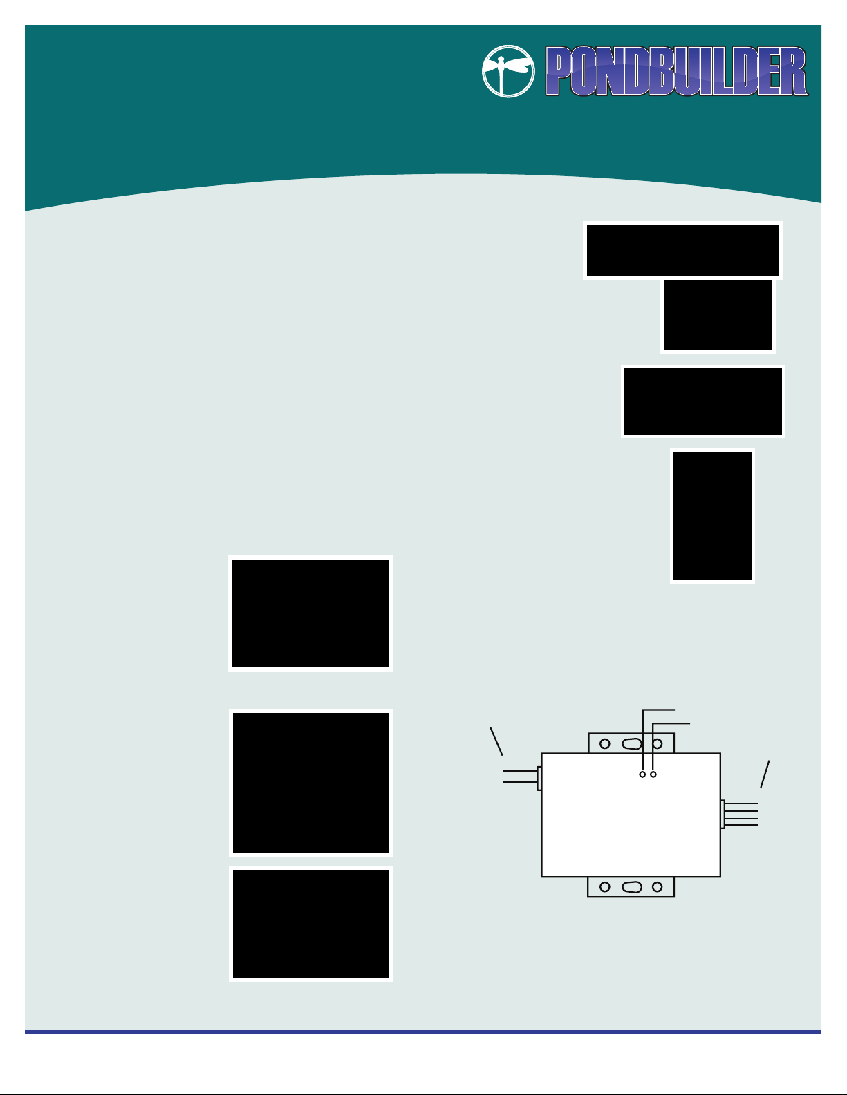
Black wire:GND
SAFETY INFORMATION
CONNECT DIAGRAM
1. The input voltage of this controller should be only DC12V-24V.
2. The 4 wires coming out of the controller can’t be incorrectly
interconnected or short circuit could occur.
3. Connect the wires of the controller and LED wires as per the instruction.
4. The standard warranty on the controller/remote is 1 year.
INPUT
OUTPUT
Signal light
Power light
White wire:+
Red Wire: R
Green wire: G
Blue wire: B
power
signal
Red wire:+12V~24V