Atlantic ColorFalls CC06 User manual

1-877-80-PONDS
www.atlanticwatergardens.com
Includes Models:
Couvre les modèles :
Incluye los modelos:
CC06
CC12
CC24
CC36
Operating Manual
Manuel d’utilisation
Manual de operación

2
Introduction
Thank you for choosing Atlantic’s Color Changing Colorfalls. The Colorfalls are
designed for use in Pond-free and fountain applications. The Color Changing
Colorfalls feature a larger opening which produces a thicker water sheer and less
clogging from debris in the water, a remote controlled Color Changing LED light
bar, and a removable back plate that provides access to the interior of the spillway
for easy maintenance and winterizing.
Prior to Operation and Installation
Caution:
• DONOToperatethisproductunderanyconditionotherthanthose
for which it is specified. Failure to observe these precautions can lead
to electrical shock, product failure, or other problems.
• FollowallaspectsofelectricalcodeswheninstallingtheColor
Changing Colorfalls.
• Toreducetheriskofelectricalshock,connectonlytoa110volt
receptacle protected by a ground fault circuit interrupter (GFCI).
• TheinputpowertotheColorChangingControlModuleis12voltAC.
TheControlModulecanbeconnectedtoalargeroutdoorlighting
transformer;howeverthismustbedonebetweentheControlModule
andthetransformer.RemovingtheControlModuleortamperingwith
thecordbetweentheControlModuleandtheColorfallswilldamage
the light bar and void warranty.
• TheControlModuleisweatherresistantwithanIP54rating.Donot
submersetheControlModuleorexposeittoheavyrainfall.Itmustbe
mounted off the ground close to the power source. Failure to do so will
void the warranty.
• ColorfallsaredesignedforuseinPond-freeandfountainapplications.
Colorfalls are not intended for use in water gardens or any pond with
plant or aquatic life.
The ColorFalls must be accessible for service and maintenance. Installing the
ColorFalls so that the entire body is removable is highly recommended. Do not
glue the cap stones above the ColorFalls or permanently mortar the ColorFalls
in place.
TheColorfallscansupport40lbs.perlinearfoot(e.g.a24”Colorfallscansupport
80lbs.).Iftheweightontheweirexceedsthatamount,youwillneedtoprovidea
lintel support for the added weight. This support should still make contact with the
weir to prevent it from shifting.

3
See the chart below for the recommended placement of the Colorfalls above the
basinorpool.IftheplacementoftheColorfallsexceedstherecommendedheight,
water loss will increase significantly due to splash and wind drift.
Colorfalls Maximum Falls
Height Above Basin Flow Rate
CC06 18” 600 GPH
CC12 24” 1200 GPH
CC24 30” 2400 GPH
CC36 36” 3600 GPH
Installation of Color Changing Colorfalls
The opening in the wall where the Colorfalls will be placed is important to the
function of the Colorfalls. If it is not level and free of debris the Colorfalls will not
function properly. The base of Colorfalls body as well as the bottom of the spillway
lip must be supported by the
opening in which it is placed.
The top side of the opening
must also be in contact with the
Colorfalls to prevent it from
shifting.SeeFigure1forthe
proper sizing of the opening for
the Colorfalls.
Plumbing A Single Colorfalls
Each ColorFalls spillway
is equipped with three
convenient1½”threadedinlets
toaccommodate1½”Sch40MPT
fittings. Choose one or more of
the three inlets for plumbing: you
can either plumb directly into the
back center of the unit, or into both sides. (Plumbing the ColorFalls from one side
only will produce an uneven water sheer. Feed lines must be connected to both
sides to ensure an even water flow.) Close off the unused inlet(s) with the provided
plugs.TheplugshaveO-ringssealsandcanbeinstalledwithoutthreadsealant.
Installing a ball valve (not included) on the feed line between the pump and the
Colorfalls is recommended for added control of water flow.
33/8”
4”
4”
½”
Figure 1

4
Plumbing Modular Colorfalls
ConnecttheColorfallstogetherusingthe1½”threadedconnector(included).
Begin by installing one end of the connector into the side inlet of one Colorfalls.
Align the second Colorfalls and spin it onto the threaded fitting (screwing the two
units together). Before they are completely tightened, install the double sided
gasket (included) at the end of the end of the spillway between the units. This
will create a watertight seal where the spillways meet. Pull the spillways of the
ColorfallsapartwhilecompletingthenalturnoftheColorfallsbody.Onceyou
have ensured proper alignment, press the spillways of the two units together
(sandwiching the gasket) to ensure it is in contact with both units.
When plumbing multiple Color Changing Colorfalls together, use the back center
inlet on each individual Colorfalls, plugging the side inlets, regardless if you are using
one pump or multiple pumps. This will balance the flow of water going to the falls.
Note: If plumbing two different sized Colorfalls together, a ball valve must be added
on each vertical feed line to adjust the water flow into each unit.
The individual feed lines
to each Colorfalls should
be1½”PVC.Ifusingone
pump to feed multiple
Colorfalls, the main feed
lineshouldbe2”or
larger. The main feed line
should be run horizontally
along the back of the wall
withvertical1½”feed
lines branching off to
each Colorfalls (Figure 3).
Operation
Technical Data
(Control Module)
Working Temperature:
0ºF-140ºF(-20°C-60ºC)
Output:3circuits(R/G/B)
1½” connector fitting
Figure 2
Figure 3
1½” 1½”
2” Feed
Lines
InputPower:AC12V
OutputPower:DC12V,<144W
OutputCurrent:<4A/circuit

5
Installation Requirements
1. TheControlModuleisweatherresistantwithanIP54rating.Donotsubmerseit
orexposeittoheavyrainfall.Itmustbemountedoffthegroundclosetothe
power source. Failure to do so will void the warranty.
2. Ensurethatallcableconnectionsaresecure.
3. Installthecontrolboxinawellventilatedareatoensurethatthemodule
operates in within its working temperature specified above.
4. Verifythatthecontrolmoduleinputvoltageis12voltAC.Werecommendthat
you use the transformer provided with this unit.
5. Donotconnectthepowerbeforethecordconnectionsarenished.
6. DonotcutoralterthecordbetweentheColorfallsandtheControlModule.
7. The remote control requires three (3) AAA batteries (not included).
Connecting the Light Bar
The Colorfalls light bar will not operate if plugs are aligned incorrectly. The
sixprongedconnectorshaveraisedarrowsthatindicatesproperalignment.
Follow the connecting chart below to connect all cables. Ensure that the unit is
not plugged in while connecting.
LED Light Strip Control Module Transformer
LED Light Strip
Atlantic’sCCCM05MasterController(soldseparately)enablesuptoveindividual
Color Changing light bars to be synchronized to change colors at the same time
usingoneremote.Inthisapplication,onlyoneControlModuleandoneremote
arerequired.UseaControlModuleandremotefromanyColorfallsanditwill
controlalllightbarswhenusedwiththeCCCM05MasterController.Replacethe
transformerfromyourColorfallswiththe80watttransformerfromtheMaster
Controller,andconnectthe5-WaysplittersuppliedwiththeCCCM05betweenthe
ControlModuleandthelightbars.Seetheconnectingchartbelowfordetails.
Transformer
Control Module
(2) 3-Way Splitters

6
Remote Control Functions
Preset Light Changing Modes
AOn/Off Button
Touch for one second to turn on or off.
B
Mode Selection
Touch for one second to switch between Color
WheelandPresetLightChangingModes
CColor Wheel
DPreset Light Changing Mode Selection (Forward)
EPreset Light Changing Mode Selection (Backward)
FBrightness / Speed (Up)
GBrightness / Speed (Down)
A
C
D
E
F
G
B
Indicator Lamp
1Solid Crystal White
2Continuous full spectrum fade change
3Solid Red
4Solid Green
5Solid Blue
6Solid Aqua
7Solid Purple
8Solid Yellow
9Red-Green-Blue jump change
10 7 color jump change
11 Red-Green-Blue dimmer change
12 7 color dimmer change
13 7 color dimmer then
7 color jump change
14 Flashing Red
15 Flashing Green
16 Flashing Blue
17 Flashing Red and Blue
Mode Selection
• ToswitchtotheColorWheel:holdtheBbuttonforthreesecondsoruntilthe
light changes to Crystal White. Hold down the B button again, and the light will
return to the last color displayed while in the Color Wheel mode. Run your
finger around the color wheel to select a new color.
• ToswitchtothePresetLightChangingModes:holdtheBbuttonforthree
seconds or until the light changes to Crystal White. Press the D button, and
the light will return to the last preset mode displayed while in the Light Changing
Modes.PresstheDandEbuttontoswitchbetweenthedifferentpresetmodes.
Changing the Brightness and Speed
InModes1-8and14-16,youcanusetheFandGkeystochangethebrightness
ofthelight.InModes9-13and17,youcanusetheFandGkeystochangethe
speed of the light transitions. There are 8 levels for each.
Synchronizing the Remote to the Control Unit
If the remote control stops working properly, please install fresh batteries. If
problems persist, the remote may need to be re-synced to the control module.
Follow the instructions below to re-sync the remote control.

7
Screws
Back Plate
LED Light Strip
Baffle
Colorfalls Body
Inlet Plugs
Figure 4
1. Unplugthetransformer.
2. HoldtheFbuttondown(Theredindicatorlampontheremotewillbeblinking).
3. While still holding the F button down, plug in the transformer. The Colorfalls will
start blinking.
• IftheColorfallsblinksthreetimesandstops,theremoteandcontrolunit
are synchronized.
• IftheColorfallsblinkssixormoretimes,itisclearingallcodes.Repeatsteps1-3.
Maintenance
Atlantic’s Color Changing Colorfalls has a removable back plate for easy cleaning
of the interior of the spillway. To clean the interior of the spillway, simply remove
thescrewsonthebackplateandremovethebafe(Figure4).Removeanylarge
obstructions that may be present and wipe down the interior with a non-abrasive
cloth.Oncenished,installthebafeandre-attachthebackplate,makingsurethat
the gasket is in place to ensure a water-tight seal.
Caution:Beextremelycautiouswhentighteningthescrews.Itisstronglyrecom-
mendedthatyoutightenthescrewswithahandheldscrewdriver.Overtightening
the screws could crack the back plate or strip the screw holes. The screws need only
be snug for the gasket to make a seal.
Forwinterizing,loosenthescrewsonthebackplatetoallowexcesswatertodrain.
Oncethewaterisremovedfromtheinteriorofthespillway,retightenthescrews.
Warranty
Colorfalls and all its components carry a one-year limited warranty. This limited
warrantyisextendedsolelytotheoriginalpurchasercommencingfromthedateof
the original purchase receipt and is void if any of the following apply:
• ThecordhasbeencutoralteredbetweentheColorfallsandtheControlModule.
• TheColorfallshasbeenmisusedorabused.

Problem Possible Cause Possible Solution
Remote is not working
(no indicator light)
Nobatteries/batteries
installed incorrectly Put in new batteries.
Remote is not working
(indicator light is on)
Remote is not synced with
ControlModule
With unit plugged in and light
bar off, hold F Key until indi-
cator light blinks three times.
Light bar will
not illuminate
Nopowertooutlet
NopowertoControl
Module
NoPowertoLightBar
Confirm power to outlet.
Check all connections, ensure
cord is not cut or damaged.
Check all connections, ensure
cord is not cut or damaged.
Light color is not
synced with remote
The arrows on the plugs are
not aligned.
Check connections, make sure
they are properly aligned.
Water leaking from
Colorfalls body
Bad plumbing connection
Gasket out of place
Screws in back plate are too
loose
Inspect all plumbing & plugs.
Ensure gasket in back plate
is in proper position.
Ensure screws are fully
tightened.
Diminished water flow
Blocked pump intake
Obstructioninplumbing
line
Debris in Colorfalls spillway
Clear debris from pump intake.
Inspect plumbing line and
clear any debris.
RefertoMaintenancesection
on page 7.
Waterfall sheer is
splitting Debris in Colorfalls spillway RefertoMaintenance
section on page 7.
1-877-80-PONDS
www.atlanticwatergardens.com
Troubleshooting Guide
Always turn off power before inspecting the Colorfalls. Failure to observe this
precaution can result in a serious accident.
Before ordering repairs, carefully read through this instruction booklet. If the
problem persists, contact your dealer.
• TheColorfallshasbeendisassembledormodiedotherthanasdescribedin
this manual.
• TheControlModuleand/orRemoteControlhavenotbeenadequately
protected from moisture.
• Thiswarrantyexcludeslabor/costsoflaborforremovalorinstallationofanyproduct.

Introduction
Mercid’avoirchoisilesmursd’eauàcouleurschangeantesmodèlesColorfalls
d’Atlantic. Les Colorfalls sont conçus pour s’utiliser dans des applications de
Pond-freeetfontaines.Lesmursd’eauàcouleurschangeantesmodèlesColorfalls
comportent une plus large ouverture qui produit une chute d’eau plus épaisse et
moinsdebourragepardesdébrisdansl’eau,unebarrelumineuseàDELàcouleur
changeantecommandéeàdistance,uneplaquearrièreamoviblepourdonneraccès
àl’intérieurdudéversoirandefaciliterl’entretienetlapréparationpourl’hiver.
Avant l’installation ou l’utilisation
Attention :
• NEfaitesPASfonctionnerleproduitdansn’importequelleconditionautreque
celle pour lequel il a été spécifié. La non-observation de ces précautions peut
entraîner une commotion électrique, mettre le produit en panne ou causer
d’autresproblèmes.
• Respecteztouslesaspectsdesnormesélectriquesquandvousinstallezlemur
d’eauàcouleurschangeantesColorfalls.
• Pourréduirelerisquedecommotionélectrique,nebranchezquesuruneprise
secteur110volts,protégéeparundisjoncteursurfuiteàlaterre(GFCI).
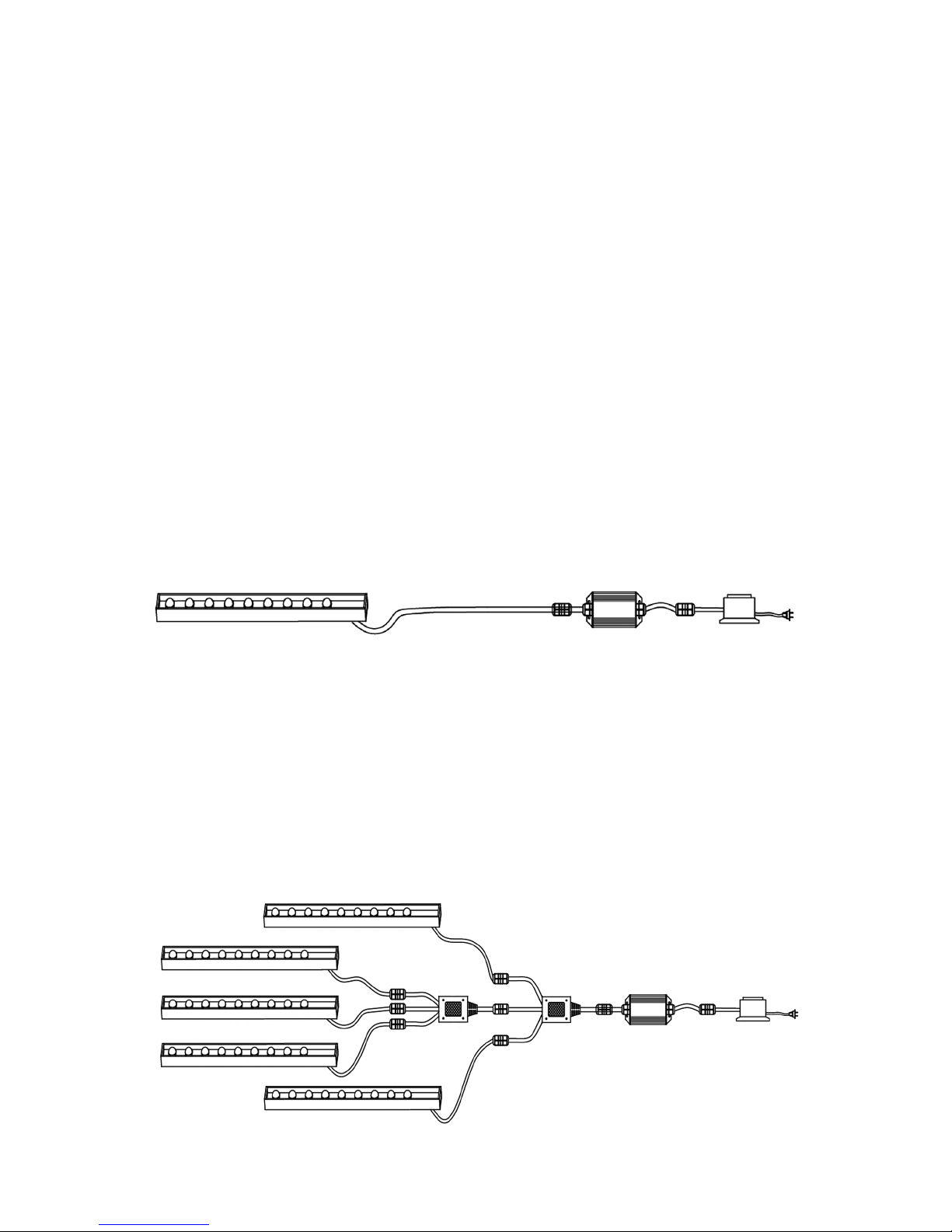
• Latensiond’entréedumoduledecommandedechangementdecouleursest
de12voltsCA.Lemoduledecontrôlepeutêtreconnectésurunplusgros
transformateurextérieurd’éclairage,cependantceladoitêtreréaliséentrele
module de commande et le transformateur. Enlever le module de commande
ou bricoler le cordon allant du module de commande au Colorfalls endommag
erait le barre lumineuse et annulerait la garantie.
• CemoduledecommanderésisteauxintempériesavecuneclassicationIP54.
N’immergezpascemoduledecommandeounel’exposezpasàunepluie
intense.Ilfautlemonterau-dessusdusol,prèsdesasourced’alimentation.
Nepaslefaireannuleraitlagarantie.
• LesColorfallssontconçuspours’utiliserdansdesapplicationsdePond-freeet
fontaines. Les Colorfalls ne sont pas prévus pour une utilisation dans des jardins
d’eau ou toute mare comportant de la flore ou de la faune aquatique.
LeColorFallsdoitêtreaccessiblepourlesactivitésd’entretienetdemaintenance.
InstallerleColorFallsdefaçonàcequelecorpssoitamovibleenentierestvivement
recommandé.Nepascollerlespierresdecouronnementau-dessusduColorFallsni
cimenter le ColorFalls de façon permanente.
LeColorfallspeutsupporter18,1kgpar30centimètres(c’est-à-direqu’un
Colorfallsde24”pourrasupporter36,2kg).Silepoidsdudéversoirdépassaitce
niveau,ilvousfaudraitfournirunsupportparlinteaupourlepoidsexcédentaire.Ce
support doit toujours rester en contact avec le déversoir pour éviter qu’il ne ripe.
9

Consultez le tableau qui suit pour le positionnement du Colorfalls au-dessus du
bassin ou de la mare. Si le positionnement du Colorfalls dépasse la hauteur recom-
mandée, la perte d’eau augmentera sensiblement du fait des éclaboussures et de
l’eau emportée par le vent.
10
Colorfalls Hauteur max. de chute
au-dessus du bassin Débit
CC06 18” 600 GPH (37,85 L/min.)
CC12 24” 1200 GPH (75,70 L/min.)
CC24 30” 2400 GPH (151,40 L/min.)
CC36 36” 3600 GPH (227,10 L/min.)
Installation des Colorfalls à couleurs changeantes
L’ouverture dans le mur où seront placés les Colorfalls est importante pour leur
bonfonctionnement.S’iln’estpasdeniveauetexemptdedébris,leColorfalls
ne fonctionne pas correctement. La base du corps du Colorfalls ainsi que le bas
delalèvrededéversoirdoiventêtresupportésparl’ouverturedanslaquelleils
sontplacés.Lecôtésupérieurde
l’ouverturedoitégalementêtreen
contact avec le Colorfalls pour lui
éviterdeglisser.VoyezlaFigure
1pourlabonnetailled’ouverture
pour le Colorfalls.
Plomberie pour un seul
Colorfalls
Chaque déversoir de Color-
Falls est équipé de trois ports
d’admission filetés pratiques
de1-1/2”quisontcompatibles
aveclesraccordsMPTSch40de
1-1/2”.Choisiruneouplusieurs
des trois admissions pour la plom-
berie:vouspouvezlaraccorderdirectementsoitaumilieuàl’arrièredel’appareil,
soitsurlesdeuxcôtés.(RaccorderleColorFallsd’uncôtéseulementprovoqueune
chuted’eauinégale.Lesconduitesd’alimentationdoiventêtreconnectéesdes
deuxcôtésand’assurerunécoulementd’eauuniforme.)Obturerlesadmissions
nonutiliséesàl’aidedesbouchonsquisontfournis.Lesbouchons,quisontmunis
dejointstoriques,peuventêtreinstalléssanspâted’étanchéitésurleslets.
L’installationd’unrobinetàtournantsphérique(noninclus)danslaconduite
d’alimentation entre la pompe et le Colorfalls est recommandée pour plus de
contrôlesurl’écoulementdel’eau.
33/8”
4”
4”
½”
Figure 1

11
Plomberie pour un ensemble de Colorfalls
ConnecterlesColorfallsàl’aideduraccordleté(inclus)de1-1/2”.Commencez
parinstalleruneextrémitéduraccorddansl’admissionlatéraledel’undesColor-
falls.AlignerledeuxièmeColorfallsetlefairetournersurleraccordleté(visser
ensemblelesdeuxunités).Avantdelesserrercomplètement,installerlejointà
doubleface(inclus)àl’extrémitédudéversoirentrelesunités.Cecipermetde
créer un joint étanche au point de rencontre des déversoirs. Écarter les déversoirs
desColorfallstouteneffectuantlederniertourducorpsduColorfalls.Aprèsavoir
assuréunalignementcorrect,presserensemblelesdéversoirsdesdeuxunités
(intercalerlejoint)and’assurerqu’ilestencontactaveclesdeuxunités.
QuandvousreliezensembleparlaplomberieplusieursColorfallsàcouleurs
changeantes,utilisezl’entréearrièrecentralesurchaqueColorfallsindividuel,en
obturantlesentréesdecôté,quevousutilisiezuneouplusieurspompes.Cela
va équilibrer le débit de
l’eauallantauxchutes.
Remarque: pour rac-
corderdeuxColorfalls
de différentes tailles, une
vanne sphérique doit
êtreajoutéesurchaque
conduite d’alimentation
verticale pour pouvoir
régler le débit d’eau dans
chaque unité.
Les conduites individu-
elles d’alimentation de
chaque Colorfalls doivent
êtreenPCVde1½”.SivousutilisezuneseulepompepourplusieursColorfalls,
laconduited’arrivéeprincipaledoitfaire2”ouplus.Laconduited’arrivéeprinci-
paledoitcourirhorizontalementlelongdel’arrièredumur,avecdesconduites
d’alimentationverticalesen1½”verschacundesColorfalls(Figure3).
Fonctionnement
Données techniques (Module de commande)
Température de fonctionnement :
0à140ºF(-20à60ºC)
Sortie:3circuits(R/G/B)
Raccord de 1½”
Figure 2
Figure 3
1½” 1½”
Conduites
d’alimentation en 2”
Alimentationélectrique:12VCA
Tensiondesortie12VCC,<144W
Courantdesortie:<4A/circuit

Besoins pour l’installation
1. LemoduledecommanderésisteauxintempériesavecuneclassicationIP54.
Nel’immergezpasounel’exposezpasàunepluieintense.Ilfautlemonterau-dessus
dusol,prèsdesasourced’alimentation.Nepaslefaireannuleraitlagarantie.
2. Assurez-vousquetouteslesconnexionsdecâblessontbienserrées.
3. Installez le boîtier de commande dans une zone bien ventilée pour assurer que
le module travaillera dans la plage de températures de fonctionnement
mentionnée précédemment.
4. Vériezquelatensiond’entréedumoduledecommandefaitbien12voltsCA.
Nousvousrecommandonsd’utiliserletransformateurfourniaveccetteunité.
5. N’envoyezpasl’alimentationavantquelesraccordementsdecordons
soient terminés.
6. Necoupezpasoun’altérezpaslecordonentreleColorfallsetlemodule
de commande.
7. Lacommandeàdistancenécessitetrois(3)pilesdetypeAAA(nonfournies).
Raccordement de la barre lumineuse
La barre lumineuse du Colorfalls ne fonctionne pas si les bouchons ne sont pas alignés
correctement.Lesconnecteursàsixbrochescomportentdesèchessurélevéesindi-
quant l’alignement correct. Suivre le schéma de raccordement ci-dessous pour brancher
touslescâbles.S’assurerquel’appareiln’estpasbranchélorsdesraccordements.
Bande d’éclairage à DEL Module de commande Transformateur
(2) Répartit-
eur 3 voies Module
de commande
Transformateur
Bande d’éclairage à DEL
UncontrôleurprincipalCCCM05d’Atlantic(venduséparément)permetquejusqu’à
cinqbarreslumineusesàcouleurschangeantesindividuellessoientsynchronisées,an
dechangerlescouleurstoutesenmêmetempsenutilisantuneseulecommandeà
distance.Danscetteapplication,unseulmoduledecommandeetunecommandeà
distancesontnécessaires.Utilisezunmoduledecommandeetunecommandeà
distance depuis n’importe quel Colorfalls et cela va piloter toutes les barres
lumineusesenutilisationavecuncontrôleurprincipal
CCCM05.Remplacezletransformateurdevos

13
Fonctions de commande à distance
Modes de changement de consigne d’éclairage
ABouton M/A
Àtoucherpendant1spourcommuter.
B
Sélection de mode
Àtoucherpendant1spourcommuterentredisque
des couleurs et changement de consigne d’éclairage
CDisque des couleurs
DMode de changement de consigne d’éclairage
(augmenter)
EMode de changement de consigne d’éclairage
(diminuer)
FLuminosité / Vitesse (augmenter)
GLuminosité / Vitesse (diminuer)
A
C
D
E
F
G
B
Voyant indicateur
1Blanccristallinxe
2Spectrecompletxeenfondu
3Rougexe
4Vertxe
5Bleuxe
6Vertd’eauxe
7Mauvexe
8Jaunexe
9Changement saccadé rouge-vert-bleu
10 Changement saccadé 7 couleurs
11 Changement progressif rouge-
vert-bleu
12 Changement progressif 7
couleurs
13 Changement 7 couleurs,
progressif puis saccadé
14 Rouge clignotant
15 Vertclignotant
16 Bleu clignotant
17 Rouge et bleu clignotant
Sélection du mode
• Pourpasseràlarouechromatique:appuyersurleboutonBpendanttrois
secondesoujusqu’àcequelalumièrepasseaucristalblanc.Appuyerdenouveau
surleboutonB,lalumièreretourneàladernièrecouleurafchéeen/moderoue
chromatique. Passer votre doigt autour de la roue chromatique pour sélectionner
une nouvelle couleur.
• Pourpasserauxmodesdechangementd’éclairagepréréglés:appuyersurle
boutonBpendanttroissecondesoujusqu’àcequelalumièrepasseaucristal
blanc.AppuyersurleboutonD,etlalumièreretourneauderniermodepréréglé
affiché en modes de changement d’éclairage préréglés. Appuyer sur les boutons
D et E pour basculer entre les différents modes préréglés.
Colorfallsparuntransformateurde80wattsducontrôleurprincipal,etbranchezle
répartiteur5voiesfourniavecleCCCM05entrelemoduledecommandeetles
barres lumineuses. Consultez le schéma de raccordement qui suit pour les détails.

14
Modification de la luminosité et de la vitesse
Enmodes1-8et14-16,vouspouvezutiliserlestouchesFetGpourmodierla
luminositédel’éclairage.Enmodes9-13et17,vouspouvezutiliserlestouchesFet
Gpourmodierlavitessedestransitionsdel’éclairage.Ilya8niveauxpourchacun.
Synchronisation de la télécommande avec l’unité de contrôle
Si la télécommande ne fonctionne plus correctement, installer des piles neuves.
Silesproblèmespersistent,latélécommandepeutdevoirêtreresynchronisée
au module de commande. Suivre les instructions ci-dessous pour resynchroniser
la télécommande.
1. Débrancherletransformateur.
2. MaintenirenfoncéleboutonF(levoyantrougedelatélécommandeclignote).
3. Tout en maintenant le bouton F enfoncé, brancher le transformateur. Les
Colorfallssemettentàclignoter.
• SiColorfallsclignotetroisfoisets’arrête,latélécommandeetl’unitédecontrôle
sont synchronisées.
• SiColorfallsclignotesixfoisouplus,ileffacetouslescodes.Répéterles
étapes1-3.
Vis
Plaque arrière
Bande d’éclairage
à DEL
Déflecteur
Corps du Colorfalls
Bouchons
d’entrées
Figure 4
Entretien
LeColorfallsàcouleurschangeantesd’Atlanticcomporteuneplaquearrière
amoviblepourfaciliterlenettoyageàl’intérieurdudéversoir.Pournettoyer
l’intérieurdudéversoir,enlevezsimplementlesvisdelaplaquearrièreetenlevez
ledéecteur.Dégageztouteslesgrossesobstructionsquipeuventêtreprésentes
et essuyez l’intérieur avec un chiffon non-abrasif. Une fois que c’est fait, remettez
ledéecteurenplaceetrefermezlaplaquearrière,envousassurantquelejoint
est en place afin d’assurer une bonne étanchéité.

Attention :Faitestrèsattentionenserrantlesvis.Ilestfortementrecommandéde
lefaireenutilisantuntournevisàmain.Unexcèsdeserragepeutssurerlaplaque
arrièreouendommagerleletagedestrouspourvis.Lesvisn’ontbesoinquede
comprimer suffisamment le joint pour assurer l’étanchéité.
Pourunepréparationhivernale,desserrezlesvisdelaplaquearrièrepour
permettreledrainagedel’excédentd’eau.Unefoisquel’eauestévacuéede
l’intérieur du déversoir, resserrez ces vis.
Garantie
Le Colorfalls et tous ses composants portent une garantie limitée d’un an. Cette
garantielimitéeestaccordéeseulementàl’acheteurd’origine,etcommence
àladatedelafacturedel’achatd’origine,elleestcaduquesiundecespoints
s’applique :
• LecordonaétécoupéoualtéréentreleColorfallsetlemoduledecommande.
• IlyaeumésusageouabusavecleColorfalls.
• LeColorfallsaétédémontéoumodiéd’unefaçonautrequecelledécrite
dans ce manuel.
• Lemoduledecommandeet/oulacommandeàdistancen’ontpasété
correctement protégés de l’humidité.
• Cettegarantieexclutlamain-d’œuvreetlescoûtsdelamain-d’œuvrepour
l’enlèvementoul’installationd’unproduit.

16
Problème Cause possible Solution possible
Lacommandeàdistance
ne marche pas (pas de
voyant allumé)
Pasdepiles/pilesmalinstallées Insérez des piles neuves
Lacommandeàdistance
ne marche pas (le voyant
allumé)
Pas de synchronisation avec le
module de commande
Avec l’unité branchée et la barre
lumineuse éteinte, maintenez la
toucheFjusqu’àcequelevoyant
indicateur clignote 3 fois.
La barre lumineuse ne
s’allume pas
Pas de secteur sur la prise
Moduledecommandepas
alimenté
Barre lumineuse pas alimentée
Confirmez la présence de secteur
sur la prise
Contrôleztouteslesconnexions,
vérifiez que le cordon n’est ni
entaillé ni endommagé
Contrôleztouteslesconnexions,
vérifiez que le cordon n’est ni
entaillé ni endommagé
Lacouleurdelalumière
n’est pas synchronisée
avec la télécommande
Lesèchessurleschesnesont
pas alignées.
Vériezlesconnexions,assurez-
vous d’un alignement approprié
desconnexions.
De l’eau fuit du corps de
Colorfalls
Mauvaisraccordementde
plomberie
Joint pas en place
Visdeplaquearrièrepasassez
serrées
Inspectez toute la plomberie et les
bouchons
Vériezquelejointdelaplaque
arrièreestbienplacé
Vériezlebonserragedesvis
Écoulement d’eau
diminué
Admission de pompe obstruée
Obstructiondanslaconduitede
plomberie
Débris dans le déversoir de
Colorfalls
Éliminez les débris de l’admission
de pompe
Inspectez la conduite et dégagez-la
si nécessaire
Référez-vousàlasectionEntretien
enpage14
Le déversoir du Colorfalls
se fend
Débris dans le déversoir de
Colorfalls
Référez-vousàlasectionEntretien
enpage14
1-877-80-PONDS
www.atlanticwatergardens.com
Guide de dépannage
Coupeztoujoursl’alimentationélectriqueavantd’inspecterleColorfalls.Nepas
observer cette précaution peut entraîner un accident grave.
Avant de demander des réparations, lisez attentivement ce tableau d’aide. Si le
problèmepersiste,contactezvotrerevendeur.

Introducción
Gracias por elegir las cascadas Colorfalls que cambian de colores (Color Changing)
de Atlantic. Las cascadas Colorfalls están diseñadas para utilizarse en aplicacio-
nes sin estanque y como fuentes. Las cascadas Colorfalls que cambian de colores
tienen una abertura más grande que produce una lámina de agua más gruesa y
que se obstruye menos por suciedad en el agua, una barra de luz LED que cambia
de colores controlada por control remoto, y una placa trasera removible que pro-
porciona acceso al interior del vertedero para fácil mantenimiento y preparación
para el invierno.
Antes de la instalación y puesta en funcionamiento
Precaución:
• NOpongaenfuncionamientoesteproductobajoningunacondicióndiferente
alacondiciónparalacualestádiseñado.Noseguirestasprecaucionespuede
llevar a descarga eléctrica, falla del producto u otros problemas.
• Sigatodoslosaspectosdeloscódigoseléctricosalinstalarlascascadas
Colorfalls que cambian de colores.
• Parareducirelriesgodedescargaeléctrica,sóloconecteauntomacorrientede
110voltiosprotegidomedianteinterruptordecircuitoporfallaatierra(GFCI).
• LaenergíadeentradahaciaelMódulodeControldelCambiodeColoreses
12voltiosCA.ElMódulodeControlpuedeconectarseauntransformadorde
iluminaciónexteriormásgrande;sinembargo,estodebehacerseentreel
MódulodeControlyeltransformador.ElhechoderemoverelMódulode
ControloalterarelcableentreelMódulodeControlylacascadaColorfalls
dañarálabarradeluzyanularálagarantía.
• ElMódulodeControlesresistentealaintemperieconunaclasicaciónIP54.
NosumerjaelMódulodeControlniloexpongaalluviaintensa.Éstedebe
montarseporencimadelsuelocercaalafuentedeenergía.Nohacerloasí
anularálagarantía.
• LascascadasColorfallsestándiseñadasparautilizarseenaplicacionessin
estanque y como fuentes. Las cascadas Colorfalls no están diseñadas para uso
en jardines acuáticos o estanques con plantas o vida acuática.
Las ColorFalls deben estar accesibles para darles servicio y mantenimiento. Se
recomiendainstalarlasColorFallsdemodoqueelcuerpoenterosepuedaextraer.
NopegueconadhesivolaspiedrassuperioressobrelasColorFallsnijeperman-
entemente con cemento las ColorFalls en su sitio.
LacascadaColorfallspuedesoportar40lbs.porpielineal(ejemplo,unacascada
Colorfallsde24”puedesoportar80lbs.).Sielpesosobreelvertederoexcedeesa
cantidad, usted necesitará suministrar un soporte horizontal a lo largo del borde
para el peso adicional. Este soporte deberá hacer contacto con el vertedero para
evitar su desplazamiento.
17

18
VealasiguientetablaparalaubicaciónrecomendadadelacascadaColorfallssobre
elestanqueopileta.SilaubicacióndelacascadaColorfallsexcedelaalturarecomen-
dada, la pérdida de agua aumentará significativamente debido al salpicado y arrastre
por el viento.
Colorfalls Altura máxima de la
cascada sobre el estanque Velocidad de flujo
CC06 18” 600 GPH
CC12 24” 1200 GPH
CC24 30” 2400 GPH
CC36 36” 3600 GPH
Instalación de la cascada Colorfalls que cambia de colores
La abertura en la pared donde se colocará la cascada Colorfalls es importante
para el funcionamiento de la cascada Colorfalls. Si la cascada no está nivelada y
no está libre de suciedad, la cascada Colorfalls no funcionará apropiadamente. La
base del cuerpo de la cascada Colorfalls y también la parte inferior del reborde del
vertedero deben ser soportadas
por la abertura donde la cascada
está colocada. El lado superior de
la abertura también debe hacer
contacto con la cascada Colorfalls
para evitar que ésta se desplace.
VealaFigura1paraeldimensio-
nado apropiado de la abertura
para la cascada Colorfalls.
Instalación de tubería para
una (1) cascada Colorfalls
Cada aliviadero de ColorFalls está
equipado con tres convenientes
entradasroscadasde1-1/2”para
aceptarconectoresSch40MPT
de1-1/2”.Escojaunaomásdelastresentradasparalatubería:puedeconectar
tuberíadirectamenteenelcentrodelapartetraseradelaunidad,oenambos
lados.(ConectarColorFallsalatuberíasólodeunladoproduciráunacortinade
aguadesigual.Laslíneasdealimentacióndebenconectarseaambosladospara
asegurar un flujo de agua uniforme). Cerrar las entradas no utilizadas con los
tapones suministrados. Los tapones tienen juntas tóricas y pueden instalarse sin
sellador de roscas.
Se recomienda instalar una válvula de bola (no incluida) en el tubo de alimentación
entre la bomba y la cascada Colorfalls para mayor control del flujo de agua.
33/8”
4”
4”
½”
Figura 1

Instalación de tubería para cascadas Colorfalls modulares
ConectelasColorfallsentresíconelconectorroscadode1-1/2”(incluido).Co-
mienceinstalandounextremodelconectorenlaentradalateraldeunaColor-
falls.AlineelasegundaColorfallsygírelaparaqueentreenelconectorroscado
(atornillar las dos unidades juntas). Antes de que estén completamente apretadas,
instaleelempaquedecaradoble(incluido)enelextremodelaliviaderoentrelas
unidades. Esto creará un sello hermético donde se unen los aliviaderos. Separe los
aliviaderos de las Colorfalls mientras lleva a cabo la última vuelta del cuerpo de las
Colorfalls. Una vez que haya garantizado una alineación correcta, una presionando
los aliviaderos de dos unidades (intercalando el empaque) para asegurarse de que
esté en contacto con ambas unidades.
AlinstalarlatuberíademúltiplescascadasColorfallsquecambiandecolores,
utilice la boca de entrada central trasera de cada cascada Colorfalls individual,
tapando las entradas
laterales, sin importar si
usted está utilizando una
(1)bombaomúltiples
bombas. Esto equilibrará
el flujo de agua que fluye
hacia las cascadas.
Nota: Si está colocando
tuberíaparadosColor-
falls de tamaño diferente
juntas, debe agregar una
válvula de bola en cada
líneadealimentaciónver-
tical para ajustar el flujo
de agua a cada unidad.
Los tubos de alimentación individuales hacia cada cascada Colorfalls deben ser
de1½”dePVC.Siseutilizauna(1)bombaparaalimentarmúltiplescascadas
Colorfalls,eltubodealimentaciónprincipaldebeserde2”osuperior.Eltubo
de alimentación principal debe instalarse horizontalmente a lo largo de la parte
traseradelaparedcontubosdealimentaciónverticalesde1½”queseramican
hacia cada cascada Colorfalls (Figura 3).
Accesorio conector de 1½”
Figura 2
19
Figura 3
1½” 1½”
Tubos de
alimentación de 2”

20
Funcionamiento
Datos técnicos (módulo de control)
Temperatura de trabajo:
0ºFa140ºF(-20°Ca60ºC)
Salida:3circuitos(R/V/N)
Requisitos de instalación
1. ElMódulodeControlesresistentealaintemperieconunaclasicaciónIP54.
Nolosumerjaniloexpongaalluviaintensa.Éstedebemontarseporencima
delsuelocercaalafuentedeenergía.Nohacerloasíanularálagarantía.
2. Revisequetodaslasconexionesdecablesestánapretadas.
3. Instale la caja de control en un lugar bien ventilado para garantizar que el
módulo funciona dentro de su temperatura de trabajo especificada arriba.
4. Veriquequeelvoltajedeentradadelmódulocontroles12voltiosCA.
Recomendamos que usted utilice el transformador suministrado con esta unidad.
5. Noconectelaenergíaantesdenalizarlasconexionesdecables.
6. NocortenialtereelcableentrelacascadaColorfallsyelMódulodeControl.
7. Elcontrolremotorequieretres(3)bateríasAAA(noincluidas).
Conexión de la barra de luz
La barra de luces de las Colorfalls no funcionará si los enchufes están alineados
incorrectamente. Los seis conectores con patas tienen flechas en relieve que indican
elalineamientocorrecto.Sigaelesquemadeconexiónqueapareceacontinuación
para conectar todos los cables. Asegúrese de que la unidad no esté enchufada
mientrashacelasconexiones.
Barra de luz LED Módulo de Control Transformador
ElControladorMaestroCCCM05deAtlantic(vendidoporseparado)permite
sincronizarhasta5barrasdeluzColorChangingindividualesparacambiarcolores
al mismo tiempo utilizando un solo control remoto. En esta aplicación, sólo se
requiereun(1)MódulodeControlyun(1)controlremoto.UtiliceunMódulode
Control y un control remoto de cualquiera de las cascadas Colorfalls y éste contro-
larátodaslasbarrasdeluzcuandoseutilizaconelControladorMaestroCCCM05.
ReemplaceeltransformadordesucascadaColorfallsconeltransformadorde80
wattsdelControladorMaestro,yconecteeldivisorde5víassuministradoconel
CCCM05entreelMódulodeControlylasbarrasdeluz.Veaelsiguientediagrama
deconexiónparaobtenerdetalles.
Energíadeentrada:12VCA
Energíadesalida:12VCD,<144W
Corrientedesalida:<4A/circuito
Other manuals for ColorFalls CC06
2
This manual suits for next models
3
Table of contents
Languages:
Other Atlantic Waterfall manuals