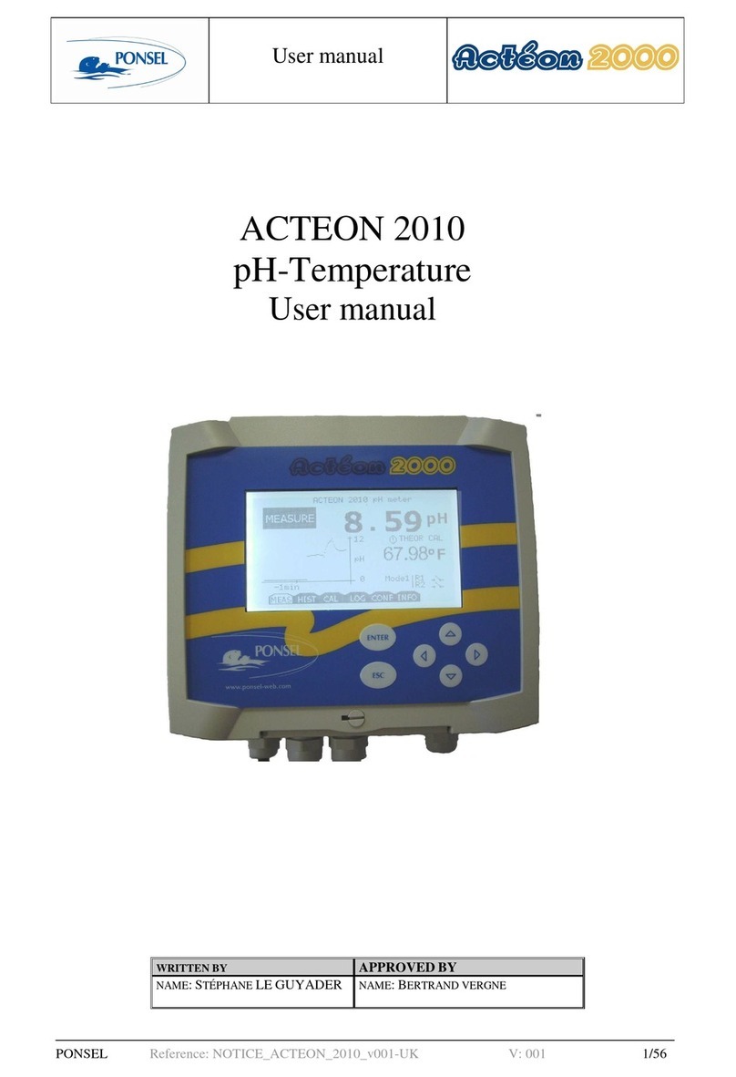
Ponsel ACTEON 5000 User manual

1
Version 2.1
Update: April 2016
PONSEL Mesure –Aqualabo Contrôle
35 Rue Michel Marion –56850 CAUDAN, FRANCE
Tel.: +33(0)2 97 89 25 30 –Fax: +33(0)2 97 76 55 72
ACTEON 5000
Digital multi-parameter transmitter
User manual

2
Version 2.1
Update: April 2016
PONSEL Mesure –Aqualabo Contrôle
35 Rue Michel Marion –56850 CAUDAN, FRANCE
Tel.: +33(0)2 97 89 25 30 –Fax: +33(0)2 97 76 55 72
CONTENTS
1. GENERAL..............................................................................................................4
1.1 Safety instructions.................................................................................................................................... 4
1.2 Labeling .................................................................................................................................................... 4
2. DESCRIPTION OF THE EQUIPMENT...................................................................5
2.1 ACTEON 5000 transmitter. ........................................................................................................................... 5
2.1.1 General description. ................................................................................................................................... 5
2.1.2 Technical characteristics. ........................................................................................................................... 5
2.2 Digital sensors.................................................................................................................................................. 6
2.2.1 OPTOD sensor: dissolved oxygen (optical technology). ........................................................................... 6
2.2.2 PHEHT sensor: pH and temperature.......................................................................................................... 7
2.2.3 EHAN sensor: Redox and temperature. ..................................................................................................... 8
2.2.4 NTU sensor: Turbidity in NTU-mg/l. ........................................................................................................ 9
2.2.5 C4E sensor: 4-electrode conductivity....................................................................................................... 10
2.2.6 CTZN sensor: inductive conductivity. ..................................................................................................... 11
2.2.7 VB5 sensor: Sludge Blanket detection..................................................................................................... 12
2.2.8 MES5 sensor: Sludge Blanket detection, Suspended Solid, Turbidity..................................................... 13
3. INSTALLATION ...................................................................................................14
3.1 Description and mounting of the controller................................................................................................ 14
3.1.1 Description of the front face..................................................................................................................... 14
3.1.2 Equipment required.................................................................................................................................. 14
3.1.3 Outline drawings of the ACTEON 5000.................................................................................................. 15
3.2 Electrical connections. .................................................................................................................................. 16
3.2.1 Safety instructions –Installation.............................................................................................................. 16
3.2.2 Description of the wiring.......................................................................................................................... 17
4. USER INTERFACE..............................................................................................20
4.1 Home screen................................................................................................................................................... 20
4.2 Navigation icons. ........................................................................................................................................... 21
5. SETTING UP........................................................................................................22
5.1 Initial start-up. .............................................................................................................................................. 22
5.2 Installation of digital sensors........................................................................................................................ 23
5.3 Selection of the parameters. ......................................................................................................................... 23
6. PROGRAMMING .................................................................................................25
6.1 Main menu..................................................................................................................................................... 25
6.2 Description of the menus. ............................................................................................................................. 25
6.2.1 Configuring the digital inputs................................................................................................................... 25
6.2.2 Configuring the On/Off inputs. ................................................................................................................ 32
6.2.3 Configuring the Analog inputs................................................................................................................. 33
6.2.4 Configuring the ACTEON 5000. ............................................................................................................. 37
6.2.5 Configuring the Analog outputs............................................................................................................... 38
6.2.6 Configuring the relay outputs................................................................................................................... 41
6.2.7 Configuring the Recording output............................................................................................................ 44
7. MAINTENANCE...................................................................................................45
7.1 Maintaining the transmitter:........................................................................................................................ 45
7.2 Maintenance of digital sensors:.................................................................................................................... 46

3
Version 2.1
Update: April 2016
PONSEL Mesure –Aqualabo Contrôle
35 Rue Michel Marion –56850 CAUDAN, FRANCE
Tel.: +33(0)2 97 89 25 30 –Fax: +33(0)2 97 76 55 72
7.2.1 OPTOD sensor. ........................................................................................................................................ 46
7.2.2 NTU sensor: Turbidity. ............................................................................................................................ 48
7.2.3 PHEHT sensor: pH/Temperature. ............................................................................................................ 50
7.2.4 ORP sensor: REDOX/Temperature.......................................................................................................... 51
7.2.5 C4E sensor: 4-electrode conductivity....................................................................................................... 52
7.2.6 CTZN sensor: Inductive conductivity. ..................................................................................................... 53
7.2.7 VB5 –MES 5 sensor: Sludge blanket detection –Sludge blanket detection/Suspended Solid/Turbidity.54
8. TROUBLESHOOTING.........................................................................................55

4
Version 2.1
Update: April 2016
PONSEL Mesure –Aqualabo Contrôle
35 Rue Michel Marion –56850 CAUDAN, FRANCE
Tel.: +33(0)2 97 89 25 30 –Fax: +33(0)2 97 76 55 72
1. General
1.1 Safety instructions
In order to maintain and ensure the good working order of the device, users must comply with the
safety precautions and warnings featured in this manual.
Assembly and activation:
- Assembly, electrical connection, activation, operation and maintenance of the measuring system
must only be carried out by specialist personnel authorized by the user of the facilities.
- Trained personnel must be familiar with and comply with the instructions in this manual.
- Make sure the power supply complies with the specifications on the nameplate before connecting the
device.
- A clearly-labeled power switch must be installed near the device.
- Check all connections before turning the power on.
- Do not attempt to use damaged equipment: it may represent a hazard and should be labeled as
faulty.
- Repairs must only be carried out by the manufacturer or by Ponsel's after-sales service department.
1.2 Labeling
Prior to any installation or start-up operation, check all the labels and symbols affixed to the
measurement device.
This symbol indicates there is a risk of electric shock or electrocution associated with the
use of the device.
This symbol indicates that the measuring device cannot be disposed of as conventional
waste.
Label on outside of device:
The ACTEON 5000 label on the right-hand face indicates the required power supply and the device's
serial number.

5
Version 2.1
Update: April 2016
PONSEL Mesure –Aqualabo Contrôle
35 Rue Michel Marion –56850 CAUDAN, FRANCE
Tel.: +33(0)2 97 89 25 30 –Fax: +33(0)2 97 76 55 72
2. Description of the equipment
2.1 ACTEON 5000 transmitter.
2.1.1 General description.
The ACTEON 5000 digital transmitter can be connected to two digital sensors in the PONSEL
MESURE range to monitor the following parameters: pH, redox, temperature, dissolved oxygen (using
optical technology), conductivity, salinity, turbidity (NTU, mg /L), Suspended Solid, Sludge blanket
detection….
The values measured are displayed and transmitted using analog or digital technology. The
preconfigured regulation functions can be used to optimize the control of processes.
The ACTEON 5000 is used in combination with a wide range of interference-resistant digital sensors,
offering pre-amplification features built into the sensor and digital signal processing. All the data
regarding the calibration, history, users and measurements is processed directly within the sensor,
thus delivering very high levels of traceability and enhancing the reliability of the measurements.
2.1.2 Technical characteristics.
Software and functionalities
Digital sensor input
2 RS-485 digital sensor inputs
2 analog outputs
Choice of 2 programmable parameters depending on the sensor connected
Programming in mode PI, PID
2 relay/digital outputs
Can be set to NO/NC
Setpoint: the measurement range (hysteresis/direction) and activation time can both
be selected,
Control of the external cleaning system
Equipment sensor fault alarm output
Atmospheric pressure sensor
For oxygen pressure compensation
Technical characteristics of the transmitter
Display
Backlit LCD graphic touch screen –Size: 95x54 mm
Analog outputs
0/4.00 –20.00 mA with galvanic isolation
Max. load 250
Relay outputs
6 A /250 V
Operating conditions
Range of operating temperatures: -15 °C to 50 °C
Storage/shipping temperature -15 °C to 50 °C
Power supply/Electrical
protection
100-240 V ac/dc 50-60 Hz
- Option: 9-28 V dc/dc
- Electrical protection: complies with EN 61010-1: 2010
Casing
Dimensions (WxHxD)
213 x 185 x 84 mm
Weight
950 g
Material
Grey ABS
Ingress protection rating
IP 65
Front face
Non-reflective polyester

6
Version 2.1
Update: April 2016
PONSEL Mesure –Aqualabo Contrôle
35 Rue Michel Marion –56850 CAUDAN, FRANCE
Tel.: +33(0)2 97 89 25 30 –Fax: +33(0)2 97 76 55 72
2.2 Digital sensors.
The digital sensors in the PONSEL range are equipped with galvanic isolation and can perform digital
signal processing to optimize the reliability of the measurements and data sent to the ACTEON 5000
terminal.
All the data regarding the calibration, calibration history, users and measurements is processed
directly within the sensor and transmitted via a Modbus RS-485 link.
The range of digital sensors can be used to measure a variety of parameters: temperature, dissolved
oxygen, pH, redox potential, conductivity (4-electrode or inductive measurement principle), turbidity
and suspended solids.
2.2.1 OPTOD sensor: dissolved oxygen (optical technology).
The OPTOD dissolved oxygen sensor applies the luminescence-based optical measurement
technology and measures reliably and accurately without requiring calibration.
With no consumables or maintenance required, the OPTOD sensor gives an immediate return on the
investment. The only intervention required is to replace the DO disk every two years.
Since it does not consume oxygen, the OPTOD sensor can be used in all media; even when there is a
very weak flow of water.
The body is made of passivated 316 L stainless steel or Titanium for applications in corrosive media.
Measurements
Measurement principle
Luminescence-based optical measurement
Measurement ranges
0.00 to 20.00 mg/L
0.00 to 20.00 ppm
0-200%
Resolution
0.01
Accuracy
+/- 0.1 mg/L
+/- 0.1 ppm
+/- 1 %
Response time
90% of the value in less than 60 seconds
Recommended measurement frequency
> 5 s
Water movement
No circulation required
Temperature compensation
Via an NTC thermistor
Storage temperature
- 10 °C to + 60 °C
Temperature measurement range
0 °C to 50 °C
Accuracy
+ /- 0.5 °C
Signal interface
Modbus RS-485 (or SDI-12)
Power supply for sensor
5 to 12 volts
Power consumption
Standby: 25 µA
When sending via RS-485 (1 measurement/second): 4.4 mA
When sending via SDI-12 (1 measurement/second): 7.3 mA
Current pulse: 100 mA
Warm-up time: 100 mS
Sensor
Dimensions
Diameter: 25 mm; Length not including cable: 146 mm
Weight
Stainless steel version: 450 g (sensor + 3 m of cable)
Titanium version: 300 g (sensor + 3 m of cable)
Material in contact with the medium
Passivated 316L stainless steel. New: Titanium body
Maximum pressure
5 bar
Cable
9-wire shielded conductor, uncoated-strand polyurethane
sleeve
Ingress protection rating
IP68

7
Version 2.1
Update: April 2016
PONSEL Mesure –Aqualabo Contrôle
35 Rue Michel Marion –56850 CAUDAN, FRANCE
Tel.: +33(0)2 97 89 25 30 –Fax: +33(0)2 97 76 55 72
2.2.2 PHEHT sensor: pH and temperature.
This PONSEL sensor is fitted with an Ag/AgCl reference electrode, used to measure pH and redox, in
a "PLASTOGEL"® KCl-saturated plasticized electrolyte.
The Plastogel® electrolyte is in direct contact with the external environment without interposition of
capillary or porous material. There is therefore no risk of fouling or deactivating the reference
electrode.
The electrode used to measure the pH is a pH-sensitive glass bulb (made from special glass) welded
to the end of a crystal tube, and the electrode for Redox measurements is a platinum disk.
Temperature: measured by an NTC thermistor inserted in a stainless steel sheath.
pH measurement
Measurement principle (pH)
pH/reference combined electrode: special glass,
Ag/AgCI reference. Gel (KCI) electrolyte
Measurement range
0 –14 pH
Resolution
0.01 pH
Accuracy
+/- 0.1 pH
Measurement of the Redox
Measurement principle (Redox)
Redox/reference combined electrode: Platinum disk,
Ag/AgCI reference. Gel (KCI) electrolyte
Measurement range
- 1000.0 to + 1000.0 mV
Resolution
0.1 mV
Accuracy
2 mV
Response time
< 5 s
Temperature measurement
Measurement principle (T°C)
NTC thermistor
Operating temperature
0.00 °C to + 50.00 °C
Resolution
0.01 °C
Accuracy
0.5 °C
Response time
< 5 s
Storage temperature
0 °C to + 60 °C
Ingress protection rating
IP 68
Signal interface
Modbus RS-485 as standard and SDI-12 as an
option
Measurement refresh rate
< 1 second maximum
Power supply for sensor
5 to 12 volts
Power consumption
Standby: 25 µA
When sending via RS-485 (1 measurement/second):
3.9 mA
When sending via SDI-12 (1 measurement/second):
6.8 mA
Current pulse: 500 mA
Sensor
Dimensions of fitted sensor
Lower part: 21 mm in diameter; 92 mm long,
Upper part: 27 mm in diameter; 103 mm long,
Length of fitted sensor: without cable gland 210 mm;
Length with cable gland: 260 mm.
Weight
350 g (sensor + cable)
Material in contact with the medium
PVC, POM-C, special pH glass, platinum,
polyurethane
Maximum pressure
5 bar
Cable/connection hardware
9-wire shielded conductor, uncoated-strand
polyurethane sleeve

8
Version 2.1
Update: April 2016
PONSEL Mesure –Aqualabo Contrôle
35 Rue Michel Marion –56850 CAUDAN, FRANCE
Tel.: +33(0)2 97 89 25 30 –Fax: +33(0)2 97 76 55 72
2.2.3 EHAN sensor: Redox and temperature.
The PONSEL sensor incorporates a reference electrode, used for ORP measurements, such as Ag /
AgCl in saturated KCl electrolyte plasticized "PLASTOGEL" ®.
The electrolyte "PLASTOGEL" ® communicates directly with the external environment without
interposition of capillary or porous. So there is no risk of clogging or defusing the reference.
The measuring electrode is in platinum (3,5mm2) presented in sealed ring on a glass rod and is for in-
situ measurements continuously
Temperature: measures via CTN.
ORP Measure
Principle of ORP measure
Combination Electrode (ORP/reference) platinium
ring, Reference Ag/AgCI. Gelled electrolyte (KCI)
Range of measures
- 1000.0 to + 1000.0 mV
Resolution
+/- 0.1 mV
Precision
+/- 10 mV
Answer time
< 90 s
Temperature measurement
Principle of measure T°C
CTN
Temperature
0,00 °C to + 50.00°C
Resolution
0.01 °C
Precision
+/- 0.5 °C
T90
< 300 s
Temperature of storage
0°C to + 60°C
Protection scale
IP 68
Interface signal
Modbus RS-485 standard and SDI-12 in option
Refresh rate measurement
Maximum < 1 second
Sensor power
5 to 12 volts
Consumption
Standby : 25 µA
Average RS485 (1 measure/second) : 20 mA
Pulse current : 500 mA
Heating time : 100 mS
Sensor
Dimensions of sensor mounted
Mounted sensor length: gland (262 mm) not
included ;
Length with gland : 324 mm.
Weight
350 g (sensor + cable)
Material in contact with the environment
PVC, POM-C,platinum, Polyurethane
Maximum Pression
5 bars
Cable/ connection
9-wire shielded conductor, uncoated-strand
polyurethane sleeve

9
Version 2.1
Update: April 2016
PONSEL Mesure –Aqualabo Contrôle
35 Rue Michel Marion –56850 CAUDAN, FRANCE
Tel.: +33(0)2 97 89 25 30 –Fax: +33(0)2 97 76 55 72
2.2.4 NTU sensor: Turbidity in NTU-mg/l.
The measuring principle is based on nephelometry: a diode emits infrared light (850 nm) and an IR
receiving diode, set to one side at an angle of 90°, detects the amount of scattered light (standardized
measurement). The sensor can be calibrated using a Formazine standard.
This very economical optical technology requires very little maintenance and no consumables.
Measurements
Measurement principle
Scattering of IR at 90°
Measurement ranges
0 to 4,000 NTU in 5 ranges:
0 - 50 NTU
0 –200 NTU
0 –1,000 NTU
0 –4,000 NTU
AUTO range
0 to 4,500 mg/L range
Calibration:
0-500 mg/L range, as per
standard NF EN 872
range >500 mg/l as per standard
NF T 90 105 2
Resolution
from 0.1 to 1, set automatically as a function of the range
Accuracy
< 5% of the NTU value recorded
Response time
< 5 s
Operating temperature
0 °C to + 50 °C
Temperature measurement
Via an NTC thermistor
Storage temperature
-10 °C to + 60 °C
Signal interface
Modbus RS-485 as standard and SDI-12 as an option
Maximum refresh rate
< 1 second
Power supply to sensor
5 to 12 volts
Power consumption
Standby: 40 µA / Warm-up time: 100 mS/ Current pulse: 500 mA
When sending via RS-485 (1 measurement/second): 820 µA
When sending via SDI-12 (1 measurement/second): 4.2 mA
Sensor
Dimensions
Diameter: 27 mm; Length not including cable: 170 mm
Weight
300 g (with 3 meters of cable)
Materials
PVC, POM-C, PMMA, Polyamide
Maximum pressure
5 bar
Cable/connection hardware
9-wire shielded conductor, uncoated-strand polyurethane sleeve
Ingress protection rating
IP68

10
Version 2.1
Update: April 2016
PONSEL Mesure –Aqualabo Contrôle
35 Rue Michel Marion –56850 CAUDAN, FRANCE
Tel.: +33(0)2 97 89 25 30 –Fax: +33(0)2 97 76 55 72
2.2.5 C4E sensor: 4-electrode conductivity.
The operation of the sensor is based on 4-electrode conductivity technology: an alternating current at
constant voltage is set up between a pair of graphite primary electrodes. The secondary electrodes,
made from platinum, adjust the drive potential at the primary electrodes to compensate for any fouling.
The voltage measured between the primary electrodes varies depending on the resistance of the
medium, and thus the conductivity.
Measurements
Measurement principle
4-electrode type conductivity sensor (2 graphite +
2 platinum).
Conductivity measurement range
0 - 200.0 µS/cm
0 - 2,000 µS/cm
0.00 - 20.00 mS/cm
0.0 - 200.0 mS/cm
Resolution
from 0.01 to 1, depending on the range
Accuracy
+/ 1 % of full scale
Salinity measurement range
5-60 g/kg
TDS-KCl range
0 –133,000 ppm
Response time
< 5 s
Operating temperature
0 °C to 50 °C
Temperature compensation
Via an NTC thermistor
Storage temperature
- 10 °C to + 60 °C
Signal interface
Modbus RS-485 as standard and SDI-12 as an
option
Measurement refresh rate
< 1 second maximum
Power supply for sensor
5 to 12 volts
Power consumption
Standby: 25 µA
When sending via RS-485 (1 measurement/second):
6.3 mA
When sending via SDI-12 (1 measurement/second):
9.2 mA
Current pulse: 500 mA
Sensor
Dimensions
Diameter: 27 mm; Length not including cable:
177 mm (not including temperature sensor)
Weight
350 g (sensor + 3 m of cable)
Materials in contact with the medium
PVC, POM-C, stainless steel
Maximum pressure
5 bar
Cable/connection hardware
9-wire shielded conductor, uncoated-strand
polyurethane sleeve
Ingress protection rating
IP68

11
Version 2.1
Update: April 2016
PONSEL Mesure –Aqualabo Contrôle
35 Rue Michel Marion –56850 CAUDAN, FRANCE
Tel.: +33(0)2 97 89 25 30 –Fax: +33(0)2 97 76 55 72
2.2.6 CTZN sensor: inductive conductivity.
The operation of the CTZN sensor is based on a conductive induction measurement principle.
A ring-type coil is excited at a fixed frequency and the response is retrieved on a second coil, linked to
the excited coil. The coupling between the coils varies depending on the conductivity of the conducting
solution present.
Measurements
Measurement principle
Inductive conductivity sensor with temperature compensation
Conductivity measurement range
0.0 to 100.0 mS/cm
Resolution
0.1
Salinity measurement range
5-60 g/kg
Operating temperature
0 to 50 °C
Temperature compensation
Via an NTC thermistor or an external measurement
Measurement accuracy of T°C
0.1 °C over a range of 0-40 °C
Response time
T90<30 s
Storage temperature
-10 °C to 60 °C
Signal interface
Modbus RS-485 and SDI-12
Measurement refresh rate
< 1 second maximum
Power supply for sensor
5 to 28 volts, max. voltage: 30 V
Power consumption
Automatic standby of < 50 µA, warm-up time: 100 ms
When sending via Modbus RS-485/ Range 0-100 mS/cm
Vin 5V
Vin 12 V
Vin 24 V
1
measurement/s
31 mA
15.5 mA
11.5 mA
Max. current peak of 700 mA for 2 mS, 350 mA for 150 mS
Sensor
Dimensions
Max. diameter: 62.4 mm, Length: 196 mm
Weight
700 g
Materials in contact with the medium
EPDM, PVC, stainless steel
Maximum pressure when immersed
5 bar
Cable/connection hardware
9-wire shielded conductor, uncoated-strand polyurethane
sleeve
Ingress protection rating
IP68

12
Version 2.1
Update: April 2016
PONSEL Mesure –Aqualabo Contrôle
35 Rue Michel Marion –56850 CAUDAN, FRANCE
Tel.: +33(0)2 97 89 25 30 –Fax: +33(0)2 97 76 55 72
2.2.7 VB5 sensor: Sludge Blanket detection.
The principle of measure is based on the mitigation of the Infra-Red signal in 870 nm through an
optical path of 5mm. The sensor delivers measures in Sludge Blanket detection in % of transmission
IR. For a better precision, the optics of the sensor are regulated in temperature.
Measurements
Measurement principle
Optical IR (870 nm) based on IR absorption
Range of measure
Sludge blanket : 0-100 %
Resolution
Sludge blanket : 0.01 à 0.1 %
Accuracy
Sludge blanket : +/- 2%
Response time
< 35 secondes
Temperature measure
Principle of measure
NTC
Working temperature
-5.00 °C to + 60,00°C
Resolution
0,01 °C
Accuracy
+/- 0.5 °C
Storage Temperature
-10°C to + 60°C
Degree of protection
IP 68
Singal Interface
Modbus RS-485 or SDI-12
Refreshment of the measure
Maximum < 1 seconde
Power supply
5 to 28 volts
Consumption
Standby : 25 µA (5 V)
Average RS485 (1 measure/seconde) : 4.5 mA (5V)
Average SDI12 (1 measure/seconde) : 4.5 mA (5V)
Curent Pulse : 100 mA during 30 mS
Heating times : 100 mS
Sensor
Weight
750 g (sensor)
Material
DELRIN, Nickel-plated brass, EPDM
Pressure max.
5 bars
Cable/ connexions
9-wire shielded conductor, uncoated-strand
polyurethane sleeve
Ingress protection rating
IP68

13
Version 2.1
Update: April 2016
PONSEL Mesure –Aqualabo Contrôle
35 Rue Michel Marion –56850 CAUDAN, FRANCE
Tel.: +33(0)2 97 89 25 30 –Fax: +33(0)2 97 76 55 72
2.2.8 MES5 sensor: Sludge Blanket detection, Suspended Solid, Turbidity.
The principle of measure is based on the mitigation of the Infra-Red signal in 870 nm through an
optical path of 5mm. The sensor delivers measures in Suspended Solid (g/l), Turbidity (FAU) and
Sludge Blanket detection in % of transmission IR. For a better precision, the optics of the sensor are
regulated in temperature.
For a measure of Suspended Solid, the sensor is directly calibrated on the material to be measured
(sample of sludge).
In Turbidimeter version the sensor delivers measures on a range 0-4000 FAU (Formazine Attenuation
Unit) and is calibrated with solutions of Formazine.
Temperature: measures and regulation of optics via CTN.
Suspended Solid measure
Principle of measure
Optical IR (870 nm) based on IR absorption
Range of measure
SS : 0-50 g/L
Turbidity : 0-4000 FAU
Sludge blanket : 0-100 %
Resolution
SS : 0.01 g/L
Turbidity : 0.01 à 1 FAU
Sludge blanket : 0.01 à 0.1 %
Accuracy
SS< 10 %
Turbidity : +/- 5% (range 200-4000 FAU)
Sludge blanket : +/- 2%
Response time
< 35 secondes
Temperature measure
Principle of measure
NTC
Working temperature
-5.00 °C to + 60,00°C
Resolution
0,01 °C
Accuracy
+/- 0.5 °C
Storage Temperature
-10°C to + 60°C
Degree of protection
IP 68
Singal Interface
Modbus RS-485 or SDI-12
Refreshment of the measure
Maximum < 1 seconde
Power supply
5 to 28 volts
Consumption
Standby : 25 µA (5 V)
Average RS485 (1 measure/seconde) : 4.5 mA (5V)
Average SDI12 (1 measure/seconde) : 4.5 mA (5V)
Curent Pulse : 100 mA during 30 mS
Heating times : 100 mS
Sensor
Weight
750 g (sensor)
Material
DELRIN, Nickel-plated brass, EPDM
Pressure max.
5 bars
Cable/ connexions
9-wire shielded conductor, uncoated-strand
polyurethane sleeve
Ingress protection rating
IP68

14
Version 2.1
Update: April 2016
PONSEL Mesure –Aqualabo Contrôle
35 Rue Michel Marion –56850 CAUDAN, FRANCE
Tel.: +33(0)2 97 89 25 30 –Fax: +33(0)2 97 76 55 72
3. Installation
3.1 Description and mounting of the controller.
3.1.1 Description of the front face.
1
Touch screen
2
Screws securing lower cover (2 screws)
3
Upper cover –do not open.
4
Lower cover - remove to make electrical
connections
5
Four cable glands
3.1.2 Equipment required.
The ACTEON 5000 unit is shipped with a bag containing 2 mounting brackets (with 2 pan head
screws) and a set of 12 connectors (two 5-contact connectors, three 4-contact connectors, three 3-
contact connectors, three 2-contact connectors and one 1-contact connector to connect up the power
supply).
Equipment required for installing the unit and for making the electrical connections:
- PH1x75 mm cross head screwdriver for attaching the unit's mounting brackets and for the screws
securing the cover which protects the electrical connections,
- 2.0 x 75 mm flat-blade screwdriver for working on the various electrical connection terminals.
To mount the ACTEON 5000 on a wall, use M5 screws (with a head size of < 10.8).

15
Version 2.1
Update: April 2016
PONSEL Mesure –Aqualabo Contrôle
35 Rue Michel Marion –56850 CAUDAN, FRANCE
Tel.: +33(0)2 97 89 25 30 –Fax: +33(0)2 97 76 55 72
3.1.3 Outline drawings of the ACTEON 5000.
Overall dimensions of the ACTEON 5000.
Diagram 1: Outline drawing for the ACTEON 5000 unit
Dimensions when mounted on a wall.
Diagram 2: Outline drawing for the ACTEON 5000 unit –wall mounting
A
225
B
198
C
165
D
178.5
E
198
A
213 mm
B
185 mm
C
84 mm
a1
179.3 mm
b1
125 mm
b2
111.3 mm
c1
71.5 mm
c2
53.5 mm

16
Version 2.1
Update: April 2016
PONSEL Mesure –Aqualabo Contrôle
35 Rue Michel Marion –56850 CAUDAN, FRANCE
Tel.: +33(0)2 97 89 25 30 –Fax: +33(0)2 97 76 55 72
3.2 Electrical connections.
3.2.1 Safety instructions –Installation.
Isolate the power supply to the measuring device before performing any electrical connection work.
The electrical wiring and cabling work must be performed exclusively by authorized
personnel.
Due to the risk of electrocution, systematically isolate the power supply to the controller
before performing electrical connection work.
Warning for the model supplied with 10 –30V
Risk of electrocution: do not connect a device operating in mains power mode to a
model supplied with 10-30 V.
Risk of electrocution: the connection of a protective earth (PE) is compulsory when
wiring and cabling both 100-240 Va.c. and 10-30 Vd.c. models.
Warning for wiring the relays
Fire risk. Since the relay contacts have a nominal value of 6 A, the external loads
connected to the relays must be fitted with devices which limit the current to < 6 A.
Open the unit's lower cover to access the controller's wiring terminals.
Unscrew the two screws which hold the lower protective cover.
Before removing the cover, loosen all the cable glands so that the cables can slide in and out.
Figure 3 shows the transmitter's wire connection zone when the lower protective cover is removed.

17
Version 2.1
Update: April 2016
PONSEL Mesure –Aqualabo Contrôle
35 Rue Michel Marion –56850 CAUDAN, FRANCE
Tel.: +33(0)2 97 89 25 30 –Fax: +33(0)2 97 76 55 72
3.2.2 Description of the wiring.
Diagram 3: Photograph showing the terminals on the circuit card
Diagram 4: Diagram of the terminals affixed (as a self-adhesive label) to the protective cover
Identification
Description
Terminal
identification on
circuit card
Terminal identification on
protective cover (self-adhesive
label)
1 –Power Supply
Option
110-230 V a.c. power supply
Yellow and green - Earth
Blue - Neutral
Brown - Phase
10-30 V d.c. power supply
Black
Red
T (-)
N (+)
P
T (-)
N (+)
P
E
N
P
-
+
NC
2 –ON/OFF
INPUT
Two dry contract inputs
WAKE –Inactive
GND –Inactive
ET1
GND
ET2
GND
WAKE –Inactive
GND –Inactive
ET1
GND
ET2
GND
3 –Digital
sensors
RS485 - INPUT
Two digital sensor inputs
V- sensor power supply: Black
Shielding –Yellow and Green
RS485 - Green
GND
GND
B
GND
SHIELD
B
A
B

18
Version 2.1
Update: April 2016
PONSEL Mesure –Aqualabo Contrôle
35 Rue Michel Marion –56850 CAUDAN, FRANCE
Tel.: +33(0)2 97 89 25 30 –Fax: +33(0)2 97 76 55 72
RS485 - White
V+ sensor power supply: Red
A
12V
A
12V
4 –ANALOG
OUTPUT
Two analog outputs
0-20 mA or 20-0 mA or 4-20 mA or 20-4
mA
Output 1: -
Output 1: +
Output 2: -
Output 2: +
GND
SA1
GND
SA2
GND
SA1
GND
SA2
5 –RELAY
OUTPUT
2 relay outputs
Output 1: Release (default is NC)
Output 1: Switch
Output 1: Operate (default is NO)
Output 2: NC
Output 2: Switch
Output 2: NO
R1
C1
T1
R2
C2
T2
R1
C1
T1
R2
C2
T2
6 –USB
USB port
For downloading data
USB
7 –Ethernet
Ethernet option
ETH
8 –485 OUTPUT
One RS485 output
RS485 (-)
RS485 (+)
G
B
A
GND
B
A
9 - ANALOG
INPUT
Two analog inputs
Analog input 2
Input 2: -
Input 2: +
Analog input 1
Input 1: -
Input 1: +
Jumpers: Selection jumpers
Voltage or Current
GND
EA2
GND
EA1
U
I
GND
EA2
GND
EA1
U
I
A - RESET
RESET button
RESET
/
B- WAKE
A button which should not be activated
WAKE
/
Table 1: Description of the electrical connections

19
Version 2.1
Update: April 2016
PONSEL Mesure –Aqualabo Contrôle
35 Rue Michel Marion –56850 CAUDAN, FRANCE
Tel.: +33(0)2 97 89 25 30 –Fax: +33(0)2 97 76 55 72
Electrical connections for digital sensors:
Diagram 5 below shows the electrical connections required for digital sensors when the cable lengths
are 15 meters or less, and when the cable lengths are more than 15 meters. When a CTZN sensor is
connected, the wiring diagram to be used is that corresponding to a cable length of more than
15 meters, regardless of the length of the cable.
Diagram 5: Sensor connection for a cable length of 15 meters or less, and of more than 15 meters.
1 - red
V+ power
2 - blue
SDI-12 –Not
connected
3 - black
GND
4 - green
B " RS-485 "
5 - white
A " RS-485 "
6 -
green/yellow
Cable shield
Connect cable 3 and 6
RED
YELLOW
ORANGE
VIOLET
PINK
V+ power
2- blue
SDI-12 –Not
connected
3 - black
V- power
4 - green
B " RS-485 "
5 - white
A " RS-485 "
6 –green/
yellow
Cable shield
Cable length more than 15 meters
Connect cable 3 and 6

20
Version 2.1
Update: April 2016
PONSEL Mesure –Aqualabo Contrôle
35 Rue Michel Marion –56850 CAUDAN, FRANCE
Tel.: +33(0)2 97 89 25 30 –Fax: +33(0)2 97 76 55 72
4. User Interface
4.1 Home screen.
The figure below shows the data displayed on the home screen when two sensors are connected to
the ACTEON 5000. In this specific case, a pH/Temperature combined sensor and an oxygen sensor
are connected to the ACTEON 5000.
1
Primary parameter measured by sensor 1
10
State of the two analog outputs: in this
example, analog output 1 is assigned to
sensor No.1. The red mark indicates
4 mA.
2
Stability indicator for the primary
parameter measured by sensor 1
11
State of Relay 1. In this example, relay 1
is assigned to sensor 1 and is in an open
position.
3
Real-time value of the primary parameter
measured by sensor 1
12
Unit for the secondary parameter
measured by sensor 2
4
Primary parameter measured by sensor 2
13
Real-time value of the secondary
parameter measured by sensor 2
5
Stability indicator for the primary
parameter measured by sensor 2
14
State of the two analog outputs: in this
example, analog output 1 is assigned to
sensor No.2. The red mark indicates 4
mA.
6
Real-time value of the primary parameter
measured by sensor 2
15
State of Relay 2. In this example, relay 2
is assigned to sensor 2 and is in an open
position.
7
Secondary parameter measured by
sensor 1
16
Navigation icon used to access the main
menu
8
Unit for the secondary parameter
measured by sensor 1
17
Logos representing the analog outputs
9
Real-time value of the secondary
parameter measured by sensor 1
18
Secondary parameter measured by
sensor 2
Table 2: description of the home screen.
If only one sensor is connected to the ACTEON 5000 then lines are displayed in the lower part of the
display where the parameter information and units would normally appear.
1
2
5
4
3
6
7
8
9
10
11
12
13
14
15
16
17
18
Table of contents
Other Ponsel Transmitter manuals
Popular Transmitter manuals by other brands

Retekess
Retekess TT117 instructions

Extron electronics
Extron electronics DTP T DWP 4K D Series user guide

Eurotronic
Eurotronic ONIC 1-5 quick start guide

Broadcast Warehouse
Broadcast Warehouse TX 25/50 Technical manual

GRAUPNER
GRAUPNER mz-10c manual

i3-TECHNOLOGIES
i3-TECHNOLOGIES i3SYNC quick start guide