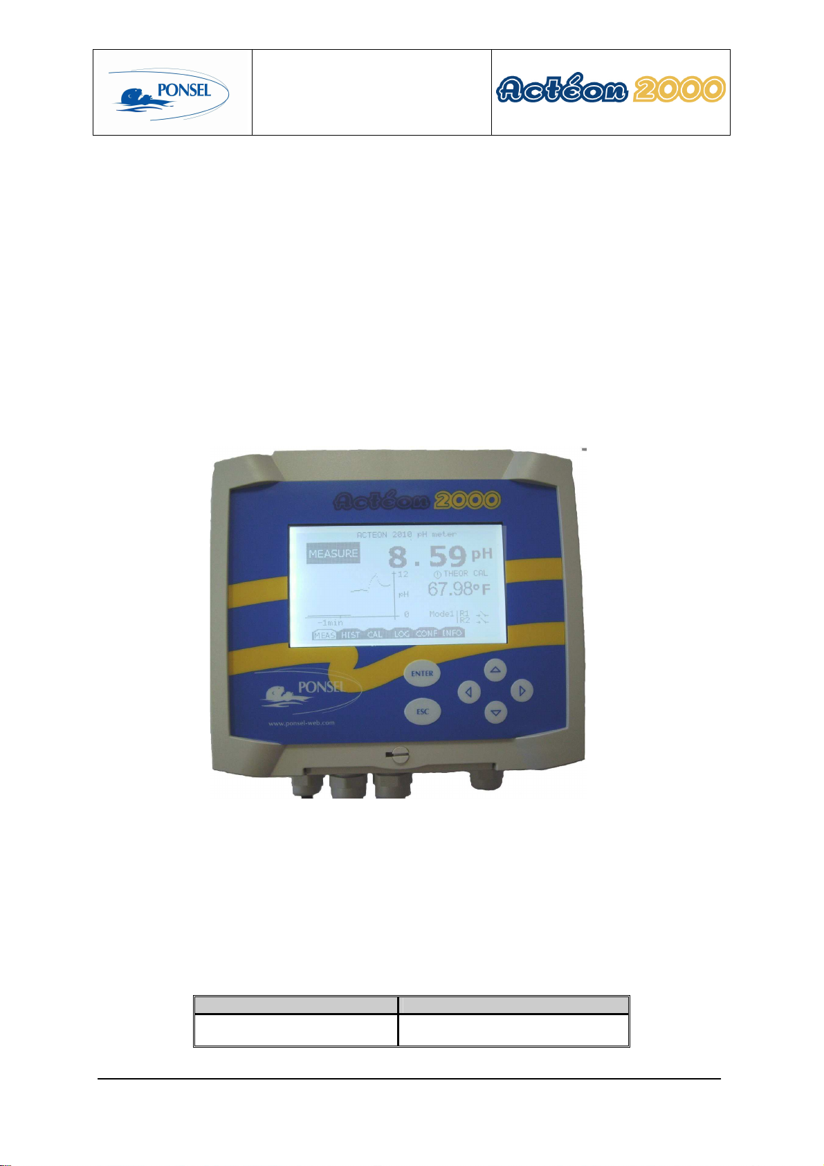
Ponsel ACTEON 2010 User manual

User manual
PONSEL Reference: NOTICE_ACTEON_2010_v001-UK V: 001 1/56
WRITTEN BY
APPROVED
BY
NAME
:
S
TÉPHANE
LE
GUYADER
NAME
:
B
ERTRAND VERGNE
ACTEON 2010
pH-Temperature
User manual

User manual
PONSEL Reference: NOTICE_ACTEON_2010_v001-UK V: 001 2/56
IMPORTANT
Read the manual carefully before switching the
device on.
So as to maintain and ensure the good working order of the device, the user must abide by the
safety precautions and warnings featured in this manual.
Assembly and activation:
- Assembly, electrical connection, activation, operation and maintenance of the
measuring system must only be carried out by specialist personnel authorised by the
user of the facilities.
- The specialist personnel must be familiar with this activation manual and are to follow
its instructions.
- Before carrying out connection, make sure that the power supply is compliant with the
directions mentioned on the nameplate.
- A clearly signposted current switch must be installed nearby the device.
- Before turning the system on, check all the connections.
- Do not activate damaged devices; they represent a hazard and should be labelled as
faulty.
- Repairs must only be carried out by the manufacturer or by a Ponsel after-sales-
service.

User manual
PONSEL Reference: NOTICE_ACTEON_2010_v001-UK V: 001 3/56
CONTENTS
1THE MEASURING SYSTEM................................................................................5
1.1
The basic system........................................................................................................................................ 5
1.1.1
A pH and temperature transmitter....................................................................................................... 5
1.1.2
A pH sensor......................................................................................................................................... 5
1.1.3
A temperature sensor........................................................................................................................... 5
1.2
Accessories................................................................................................................................................. 5
1.2.1
Consumables....................................................................................................................................... 5
1.2.2
Accessories for a tank-mounted installation without cleaning system................................................ 5
1.2.3
Accessories for a tank-mounted system with a pH sensor cleaning system........................................ 5
1.2.4
Accessories for the pH filling sensor (PONCPC-PHL-RV-10) ........................................................ 5
1.2.5
Accessories for an installation mounted inside pipes for pH (PONCPC-PHL-10) and Temperature
sensors 5
2INSTALLATION ...................................................................................................5
2.1
Mounting the ACTEON 2010 transmitter box....................................................................................... 5
2.2
Connection of the ACTEON 2010 transmitter to the pH and Temperature sensors .......................... 5
2.2.1
Acteon 2010 wiring............................................................................................................................. 5
2.3
Tank-mounting.......................................................................................................................................... 5
2.3.1
Using the stand and protective hood ................................................................................................... 5
2.3.2
Installation of a sensor with a (elbowed or straight) sensor-holder perch and nozzle (PONPPCC-
PH/EH or PONPPCD-PH/EH)......................................................................................................................... 5
2.3.3
Installation of an ESHP (Elbowed Sensor-Holder Perch) or SSHP (Straight Sensor-Holder Perch) on
a QRPM (Quick Release Perch Mount) (PONSPFR and PONSPFR2) .............................................................. 5
2.3.4
Installation of a pH sensor cleaning system ........................................................................................ 5
2.4
Installation mounted inside pipes:........................................................................................................... 5
3THE ACTEON 2010 TRANSMITTER...................................................................5
3.1
Control console.......................................................................................................................................... 5
4SUMMARY OF ACTEON 2010 MENUS..............................................................5
5THE MEASURE WINDOW...................................................................................5
6CALIBRATING THE ACTEON 2010....................................................................5
6.1
Calibrating the sensors ............................................................................................................................. 5
6.1.1
Calibrating the pH sensor at two points (complete calibration) .......................................................... 5
6.1.2
Adjusting the slope of the pH sensor................................................................................................... 5
6.1.3
Returning to theoretical calibration for measurement of pH............................................................... 5
6.1.4
Calibrating the temperature sensor at two points (complete calibration)............................................ 5
6.1.5
Adjusting the slope of the temperature sensor .................................................................................... 5
6.1.6
Returning to theoretical calibration for temperature measurement ..................................................... 5
6.2
Information on error messages during calibration of the pH sensor.................................................... 5
6.2.1
Error during calibration with the pH 7.01 buffer................................................................................. 5
6.2.2
Error during calibration with the pH 4.01 buffer................................................................................. 5
6.3
Information on error messages during calibration of the temperature sensor.................................... 5
6.3.1
Error during calibration at 0°C............................................................................................................ 5
6.3.2
Error during calibration with water at ambient temperature ............................................................... 5

User manual
PONSEL Reference: NOTICE_ACTEON_2010_v001-UK V: 001 4/56
7VIEWING THE MEASUREMENT HISTORY........................................................5
8VIEWING THE SENSOR CALIBRATION REPORT ............................................5
9CONFIGURING ACTEON 2010...........................................................................5
9.1
Configuring the averaging of the sensor response.................................................................................. 5
9.2
Configuring the trend curve..................................................................................................................... 5
9.3
Configuring the two 4-20mA outputs...................................................................................................... 5
9.3.1
Adjusting the stopped thresholds for the 4-20mA outputs.................................................................. 5
9.3.2
Calibrating the 4-20mA outputs.......................................................................................................... 5
9.4
Adjusting the relay outputs...................................................................................................................... 5
9.4.1
Configuring the relays in mode 1........................................................................................................ 5
9.4.2
Configuring the relays in mode 2:....................................................................................................... 5
9.5
Adjusting the measure units: ................................................................................................................... 5
9.6
Setting the language:................................................................................................................................. 5
9.7
Returning to the factory default values:.................................................................................................. 5
10 THE INFO MENU .................................................................................................5
11 ADJUSTING THE CONTRAST OF THE ACTEON 2010 DISPLAY ....................5
12 TECHNICAL SPECIFICATIONS:.........................................................................5
13 THE SENSORS....................................................................................................5
13.1
The pH sensor............................................................................................................................................ 5
13.1.1
Specifications...................................................................................................................................... 5
13.1.2
Description.......................................................................................................................................... 5
13.1.3
Activation............................................................................................................................................ 5
13.1.4
Maintenance........................................................................................................................................ 5
13.1.5
Cleaning .............................................................................................................................................. 5
13.2
The temperature sensor............................................................................................................................ 5
14 QUESTIONS & ANSWERS..................................................................................5
14.1
pH measurement anomalies ..................................................................................................................... 5
15 APPENDIX ...........................................................................................................5

User manual
PONSEL Reference: NOTICE_ACTEON_2010_v001-UK V: 001 5/56
Figures
Figure 1- Transmitter mounting diagram................................................................................................................ 5
Figure 2- Installation of a measuring system .......................................................................................................... 5
Figure 3– Installation including a connection box with integrated pre-amplifier ................................................... 5
Figure 4– Mount and hood for the transmitter ........................................................................................................ 5
Figure 5- Elbowed Sensor-Holder Perch................................................................................................................. 5
Figure 6– Nozzle for sensor without cleaning system............................................................................................. 5
Figure 7– Installation of a perch on a QPRM with one or two sliders.................................................................... 5
Figure 8- Installation of a pH sensor mounted inside a pipe................................................................................... 5
Figure 9- Installation of a temperature sensor mounted inside a pipe..................................................................... 5
Figure 10- Diagram of the pH sensor...................................................................................................................... 5
Figure 11- Wiring diagram for the transmitter terminal.......................................................................................... 5

User manual
PONSEL Reference: NOTICE_ACTEON_2010_v001-UK V: 001 6/56
1 The measuring system
1.1 The basic system
At a minimum, a measuring system requires the following elements:
1.1.1 A pH and temperature transmitter
PONACTEON2010 ACTEON 2010 transmitter - pH-meter and thermometer
The pH and Temperature transmitter comes complete with :
•a pH 7.01 buffer solution,
•a pH 4.01 buffer solution,
•instructions.
1.1.2 A pH sensor
Two sensors are available depending on use :
PONCPC-PHL-10 Electrolyte plastogel® pH sensor with 10-metre cable
and LEMO connector (perch-mounted or mounted inside
a pipe)
In cold liquids with very low conductivity (less than 50 µS/cm) or contaminating media, it is
recommended to use a filling sensor with bridge.
PONCPC-PHL-RV-10 Glass-bodied pH filling sensor with 10- metre cable and
LEMO connector
1.1.3 A temperature sensor
PONCPC-T-10 Temperature sensor with 10-metre cable (perch-
mounted or mounted inside a pipe)

User manual
PONSEL Reference: NOTICE_ACTEON_2010_v001-UK V: 001 7/56
1.2 Accessories
1.2.1 Accessories for a tank-mounted installation without cleaning system
PON-BJAI-E PH/EH/T IP 68 leak-tight connection box (complete with 10 metres of cable)
with integrated pre-amplifier, for connecting pH/Eh and
Temperature sensors over distances greater than 10 metres (see
Figure 3 - Installation including a connection box with an integrated
preamplifier)
PONCBMC-9 9-conductor screened cable for linking the connection box to
ACTEON 2010
PON-ACT-24V Optional 24 VDC power supply
PON-PDPCV-1 PVC stand and protective hood for an ACTEON 2010 transmitter
PON-PDPCV-2 PVC stand and protective hood for two ACTEON 2010 transmitters
PVC protective hood for an ACTEON 2010 transmitter
PVC protective hood for two ACTEON 2010 transmitters
PONPPCC-PH/EH/T Elbowed sensor-holder perch (ESHP) for pH/Eh or Temperature
sensors. Complete with nozzle and glued coupling
PONPPCD-PH/EH/T Straight sensor-holder perch (SSHP) for pH/Eh or Temperature
sensors. Complete with nozzle and glued coupling
PONBUSE-PH/EH/T Nozzle for pH/Eh (without cleaning system) or Temperature sensors.
Complete with 50 diameter BP3P glued coupling
PONCOUDE 90° elbow for closing off a sensor-holder perch
PONSPFR2C ESHP or SSHP type mount for 2 perches – 1 arm, 2 sliders – made
of stainless steel.
PONSPFR1C ESHP or SSHP type mount for 1 perch – 1 arm, 1 slider – made of
stainless steel
PONSPFR-COUL Additional slider for a QRPM system (Quick Release Perch Mount)
1.2.2 Accessories for a tank-mounted system with a pH sensor cleaning system
PONCA-HX1 Air compressor in IP65 casing for permanent cleaning, 230 V power
supply (to be used with a perch and nozzle for cleaning)
PONPPCC-PH-NET Elbowed sensor holder perch for pH type sensors. Complete with a
nozzle housing the cleaning system and rilsan tube
PONBUSE-PH-NET pps4 nozzle for pH sensors (with cleaning)
PONTUBE-NET 4 x 6 mm black rilsan tube for cleaning system, 7 metres long
complete with connector + 3 metres in the perch
1.2.3 Accessories for the pH filling sensor (
PONCPC-PHL-RV-10)
PONRAC-PH/EH-RV Connector for a filling system
PONRES-PH/EH-RV 5-litre capacity electrolyte tank for a filling system
PONROB-PH/EH-RV Tap for an electrolyte tank for a filling system
PONTUB-PH/EH-RV 10-metre tube for connecting the tank to the strainer, for a
filling system
PONCREP-PH/EH-RV Strainer for a filling system

User manual
PONSEL Reference: NOTICE_ACTEON_2010_v001-UK V: 001 8/56
1.2.4 Accessories for an installation mounted inside pipes for pH (
PONCPC-PHL-10
)
and Temperature sensors
PON4020 Tee assembly fitted with 20 x 27 male/female sockets for AP1.
To be fitted on PVC piping
PON40 40 diameter glued tee assembly (without connectors) for AP1
PONAP1 Adapter sleeve for pH and temperature sensors mounted inside
pipes
PONVCPO-63 Stainless steel 63 mm clamp type assembly mounted inside a
pipe (316 L) (for MES, OXY, Eh, pH, Temp, C2E and C4E
sensors). To be fitted with the appropriate nipple. To be fitted
on stainless steel piping
PONNIP-PH/EH Nipple for pH/Eh sensors
PONNIP-PH/EH-T Nipple for 2 pH/T or Eh/T or pH/Eh sensors
PONNIP-T Nipple for Temperature sensor
1.2.5 Consumables
PONMANU-2010
Additional User Manual
PONKCL-1M
125-ml bottle of (1M) KCl for pH and Eh filling sensors
PONKCL-2M
125-ml bottle of (2M) KCl for pH and Eh filling sensors
PONKCL-3M
125-ml bottle of (3M) KCl for pH and Eh filling sensors
PONPEPNET
125-ml bottle of pepsin cleaning solution for Eh and pH sensors
PONSOLCSV
125-ml bottle of storage solution for pH/Eh sensors
PONPH-AMP-4
125-ml bottle of pH 4 buffer
PONPH-AMP-7
125-ml bottle of pH 7 buffer
PONPH-AMP-10
125-ml bottle of pH 10 buffer

User manual
PONSEL Reference: NOTICE_ACTEON_2010_v001-UK V: 001 9/56
2 Installation
2.1 Mounting the ACTEON 2010 transmitter box
Acteon 2010 mounting diagram
A B C
Dimensions (mm) 156.5 181 195.3
Figure 1- Transmitter mounting diagram
2.2 Connection of the ACTEON 2010 transmitter to the pH and Temperature
sensors
•connection sensor – transmitter < 10 m
Figure 2- Installation of a measuring system
ACTEON 2010 transmitter, pH-meter and
thermometer
pH sensor
PONCPC-PHL-S10
Temperature sensor
PONCPC-T-10
Relay
4-20 mA Max. 10 metres
230 V~
Earth terminal
or lining-out of
230 V

User manual
PONSEL Reference: NOTICE_ACTEON_2010_v001-UK V: 001 10/56
•connection sensor – transmitter > 10 m
Comment:
If the connection cable between the pH sensor and transmitter is longer than 10 metres, a leak-tight IP 68
connection box with integrated pre-amplifier must be used (REF: PON-BJAI-E PH/EH/°C ).
Figure 3– Installation including a connection box with integrated pre-amplifier
2.2.1 Acteon 2010 wiring
See appendix (§15) at the end of the document.
2.3 Tank-mounting
2.3.1 Using the stand and protective hood
A protective hood (PON-PDPVC-1) is available for mounting the ACTEON 2010.
The hood is essential in the case of direct exposure to adverse weather or sunshine.
Figure 4– Mount and hood for the transmitter
ACTEON 2010 pH and Temperature
transmitter
Temperature sensor
PONCPC
-
T
-
10
230 V~
Relay
4-20 mA Max. 10 metres
Connection box
PON-BJAI-E PH/EH/°C pH sensor
PONCPC-PH-10
Earth terminal
or lining-out of
230 V

User manual
PONSEL Reference: NOTICE_ACTEON_2010_v001-UK V: 001 11/56
2.3.2 Installation of a sensor with a (elbowed or straight) sensor-holder perch and
nozzle (PONPPCC-PH/EH or PONPPCD-PH/EH)
For immersing the sensor in a tank, it is better to use the elbowed sensor-holder perch:
Figure 5- Elbowed Sensor-Holder Perch
Elbowed Sensor
-
Holder Perch
Sensor in nozzle
Direction o
f liquid flow
Sensor-holder perch
Glued coupling
Sensor-holder nozzle
Fixing nut
Liquid level
Min. 50 cm

User manual
PONSEL Reference: NOTICE_ACTEON_2010_v001-UK V: 001 12/56
Comment:
Use an elbowed sensor-holder in tanks that are heavily soiled in order to avoid the build up of
fibres on the perch.
Installation of the pH sensor in the nozzle:
1) Dismantle the sensor-holder perch then remove the nozzle from the bottom of the perch by removing its
tightening screw.
2) Introduce a solid wire into the perch then a string.
3) Take the sensor and remove its protective casing and two ring-type joints.
Henceforth, handle the sensor with care. Breakage of the glass bulb is not covered by the
guarantee.
4) Attach the end of the sensor to the string and lower it from the top to the bottom of the perch by pulling
on the string.
5) Remove the string then place the sensor in the nozzle and let it protrude by around twenty centimetres.
6) Replace only the ring-type joint nearest to the glass part.
7) Leave the tip of the sensor flush with the end of the nozzle, to within a millimetre. Fasten the sensor in
place by screwing the tightening screw.
8) Replace the nozzle on the perch and fasten it using the tightening screw.
9) Set the perch in a vertical position using our stand with slider or other sort of system. Adjust the
immersion parameters so that the nozzle always remains immersed and so that the more than 0.50 cm is
immersed.
10) Position the sensor so that direction of liquid flow comes from behind the nozzle in order to avoid the
build up of fibres.
Diagram of the sensor in the nozzle without the cleaning system.
Figure 6– Nozzle for sensor without cleaning system
Comment: The line out cable is to be connected to the ACTEON 200 earth terminal.
Water earth cable
pH SENSOR (
PONCPC
-
PHL
-
10)
Tightening screw
Nozzle (PONBUSE-PH/EH/T)

User manual
PONSEL Reference: NOTICE_ACTEON_2010_v001-UK V: 001 13/56
2.3.3 Installation of an ESHP (Elbowed Sensor-Holder Perch) or SSHP (Straight
Sensor-Holder Perch) on a QRPM (Quick Release Perch Mount) (PONSPFR
and PONSPFR2)
1) Fix the stainless steel QRPM to the infrastructure.
2) Next, fix a sensor-holder perch to the stainless steel QRPM as shown in the diagram below.
Figure 7– Installation of a perch on a QPRM with one or two sliders
It is possible to install a second slider in order to install a second sensor-holder perch for the temperature sensor
(see diagram above).

User manual
PONSEL Reference: NOTICE_ACTEON_2010_v001-UK V: 001 14/56
2.3.4 Installation of a pH sensor cleaning system
So as to lengthen the time between each clean, use the compressed air cleaning system (PONCA-HXI).
1) Dismantle the sensor-holder perch then remove the nozzle from the bottom of the perch by removing its
tightening screw.
2) Introduce a solid wire into the perch then a string.
3) Take the sensor and remove its protective casing and two ring-type joints.
Henceforth, handle the sensor with care. Breakage of the glass bulb is not covered by the
guarantee.
4) Attach the end of the sensor to the string and lower it from the top to the bottom of the perch by pulling
on the string.
5) Remove the string then place the sensor in the nozzle and let it protrude by around twenty centimetres.
6) Replace only the ring-type joint nearest to the glass part.
7) Leave the tip of the sensor flush with the end of the nozzle, to within a millimetre. Fasten the sensor in
place by screwing the tightening screw.
8) Replace the nozzle on the perch and fasten it using the tightening screw.
9) Set the perch in a vertical position using our stand with slider or other sort of system. Adjust the
immersion parameters so that the nozzle always remains immersed and so that the more than 0.50 cm is
immersed.
10) Position the sensor so that direction of liquid flow comes from behind the nozzle in order to avoid the
build up of fibres.
pH SENSOR (
PONCPC
-
PHL
-
10)
Compressed air duct

User manual
PONSEL Reference: NOTICE_ACTEON_2010_v001-UK V: 001 15/56
2.4 Installation mounted inside pipes:
For installations mounted inside pipes, use the tee assembly (PON-4020) and the adapter sleeve (PONAP1).
Figure 8- Installation of a pH sensor mounted inside a pipe
Figure 9- Installation of a temperature sensor mounted inside a pipe
20 x 27 connector
pH sensor (PONCPC-PHL-10)
Sleeve (PONAP1)
Tee (PON4020)
Raccord 20x27
Capteur pH (PONCPC-T-10)
Foureau (PONAP1)
T (PON4020)

User manual
PONSEL Reference: NOTICE_ACTEON_2010_v001-UK V: 001 16/56
3 The ACTEON 2010 transmitter
3.1 Control console
1
1
ENTER key for accessing menus or validating actions
2
ESC key for exiting menus or cancelling actions
3
key to move left in menus
4
5
key to move right in menus
key to increase a value or select the menu above
6
key to decrease a value or select the menu below
8
Quarter turn to lock the cover
2
5 3
4 6
8
7
7
Control screen

User manual
PONSEL Reference: NOTICE_ACTEON_2010_v001-UK V: 001 17/56
4 Summary of ACTEON 2010 menus
MEASURE
CONFIGURATION
Configuration of the language (§9.6)
4-20mA outputs
adjustment
Relays adjustments
CALIBRATION
Graphic screen adjustment (§9.2)
Configuration of the measure unit (§9.5)
GENERAL
INFORMATION
HISTORY
CALIBRATION
LOGGER
Config. of 4mA & 20mA
stop switches (§9.3.1)
Calibration of 4-20mA
outputs (§9.3.2)
Adjustment of thresholds
to mode 1 (§9.4.1)
Adjustment of thresholds
to mode 2 (§9.4.2)
Factory default configuration reminder (§ 9.7)
Gain adjust (§6.1.2)
Complete calibration (§6.1.1)
Theoretical calibration (§6.1.3)
Gain adjust (§6.1.5)
Complete calibration (§6.1.4)
Theoretical calibration (§6.1.6)
pH sensor
Temperature sensor

User manual
PONSEL Reference: NOTICE_ACTEON_2010_v001-UK V: 001 18/56
5 The measure window
In measure mode the measure screen displays various information :
20.00
°C
-
24h
4.31
MEASURE
pH
INFO
CONF
HIST
CAL
LOG
MEAS
R1
R2
!
CAL
ACTEON 2010 pH meter
pH
6
8
1
2
3
4
5
1
The pH measurement (offset in temperature)
2
Indicator of measurement status:
CAL THEOR
: The calibration coefficients are the theoretical coefficients
!
!
CAL
: The calibration point of the sensor is not correct.
6
4
Status and operating mode of relays
R1 and R2:
ACTEON
menu
5
6
Trend curve configurable from 1 minute to 24 hours (with automatic scaling)
Temperature transmitted by the temperature sensor
If the sensor is not installed or the wiring is faulty, the temperature is not displayed and the
temperature offset is brought down to 20°C.
3
: The last calibration is correct.
The contact is inactive.
The contact is active.
Mode1
No icon

User manual
PONSEL Reference: NOTICE_ACTEON_2010_v001-UK V: 001 19/56
6 Calibrating the ACTEON 2010
6.1 Calibrating the sensors
In the measure window, select the calibration menu :
20.00
°C
-
24h
4.31
MEASURE
pH
INFO
CONF
HIST
CAL
LOG
MEAS
Mode1 R1
R2
ACTEON 2010 pH meter
pH
6
8
Use the
and
keys to
move about the ACTEON
menu.
CALIBRATION
SENSORS CALIBRATION
SENSOR pH
Gain adjust
Complete calibration
Theoretical calibration
TEMPERATURE SENSOR
Zero rectification
Complete calibration
Theoretical calibration
ENTER: Validate the choice
Select the CAL menu then press the ENTER key.

User manual
PONSEL Reference: NOTICE_ACTEON_2010_v001-UK V: 001 20/56
6.1.1 Complete calibration of the pH sensor (at two points)
The following procedure enables complete calibration of your pH sensor.
It is necessary to use the 7.01 and 4.01 or 10.01 buffer solutions for this procedure.
CALIBRATION
SENSORS CALIBRATION
SENSOR pH
Gain adjust
Complete calibration
Theoretical calibration
TEMPERATURE SENSOR
Gain adjust
Complete calibration
Theoretical calibration
ENTER: Validate the choice
Use the
and
keys to
select the type of calibration
and sensor to be calibrated.
Select the
Complete calibration
menu
then press the ENTER key.
Use the
and
keys to move in
the name.
Use the
and
keys to change
the letters.
Once you have entered your name or reference,
press the ENTER key.
CALIBRATION
OF THE SENSOR pH
ESC: Cancel the procedure
ENTER: Start calibration
Enter your name:
Durant
Immerse the sensor in the pH 7.01 buffer solution
Table of contents
Other Ponsel Transmitter manuals
Popular Transmitter manuals by other brands

Retekess
Retekess TT117 instructions

Extron electronics
Extron electronics DTP T DWP 4K D Series user guide

Eurotronic
Eurotronic ONIC 1-5 quick start guide

Broadcast Warehouse
Broadcast Warehouse TX 25/50 Technical manual

GRAUPNER
GRAUPNER mz-10c manual

i3-TECHNOLOGIES
i3-TECHNOLOGIES i3SYNC quick start guide