SPRIANO SPRIANO Series User manual

OPERATING MANUAL
MN-SST50
ED-17-09
SST50 TORQUE TUBE LEVEL TRANSMITTER
ORIGINAL INSTRUCTIONS

1354
EU Declaration of Conformity
TERRANOVA® Srl
Via Gramsci 1 –26827 Terranova dei Passerini (LO) –Italy
declares on his sole responsibility that the product:
SPRIANO® Electronic Transmitters series
SST50, SST51, SST52, SST55, SST56, SST57B, SST57BL, SST59B, SST50-REM
(device controlling or regulating the limits of an industrial process, like pressure, level and vacuum)
satisfies the essential requirements and conformity assessment procedures of the following legislation:
Directive 2014/34/EU (ATEX)
EU TYPE CERTIFICATE: TI 17 ATEX 305 X
Equipment for use in potentially explosive atmospheres, suitable for Zones 0, 1, 2 (process side and external side)
II 1G Ex ia IIC T6 Ga for use in the ambient temperature range –40°C to 40°C
II 1G Ex ia IIC T5 Ga for use in the ambient temperature range –40°C to 55°C
II 1G Ex ia IIC T4 Ga for use in the ambient temperature range –40°C to 80°C
Presumption of conformity provided by the application of the harmonised standards:
EN 60079-0:2012+A11:2013 - EN 60079-11:2012
The Notified Body NB 1354 Technicka inspekcia a.s. performed Module D, Annex IV, Directive 2014/34/EU and
issued the Production Quality Assurance Notification. Periodical Surveillance is provided according to Annex IV,
Point 4, Directive 2014/34/EU by the same Notified Body.
Directive 2014/68/EU (PED)
EU DESIGN EXAMINATION CERTIFICATE: 1292/1/2017-2÷8
Pressure equipment, up to Category IV, for fluids (gases, liquids and vapours) in Group 1.
Conformity provided by the application of the harmonised standard:
EN 13445-1:2015, EN 13445-2:2015, EN 13445-5:2015
The Notified Body NB 1354 Technicka inspekcia a.s. performed Module H1, Directive 2014/68/EU and issued the
Production Examination Certificate. Periodical Surveillance is provided according to Directive 2014/68/EU by the
same Notified Body.
Directive 2014/30/EU (EMC)
Equipment with an adequate level of electromagnetic compatibility.
Presumption of conformity provided by the application of the harmonised standard:
EN 61326-1:2006
Terranova dei Passerini, 04/08/2017
Mr Sergio Valletti,
General Manager

OPERATING MANUAL
MN-SST50
ED-17-09
SPRIANO® TECHNOLOGIES - www.spriano.it –spriano@terranova-instruments.com
a TERRANOVA® Srl brand - www.terranova-instruments.com - VAT IT07848810151
Factory & Sales: Via Gramsci 1 –26827 Terranova dei Passerini (LO) –Italy
Head Office: Via Rosso Medardo 16 –20159 Milano –Italy Ph: +39 0377 919119 –Fax: +39 0377 855720
Pag. 3/48
1INTRODUCTION ................................................................................................................................ 4
1.1 Product Overview.......................................................................................................................... 4
1.2 Attention! ..................................................................................................................................... 4
1.3 Definitions And Symbols ................................................................................................................ 5
2DESCRIPTION.................................................................................................................................... 6
3INSTALLATION.................................................................................................................................. 7
3.1 Transmitter Identification.............................................................................................................. 7
3.2 General Mounting Requirements................................................................................................... 7
3.3 Mechanical Installation ................................................................................................................. 8
3.4 External Mounting Displacers ........................................................................................................ 8
3.5 Internal Mounting Displacers ...................................................................................................... 10
3.6 Top Part Orientation ................................................................................................................... 11
3.7 Electronic Head Orientation......................................................................................................... 13
3.8 Electrical Connection ................................................................................................................... 14
3.9 Intrinsic Safety Protection............................................................................................................ 17
3.10 Earthing ................................................................................................................................... 19
4OPERATIONS .................................................................................................................................. 21
4.1 Measure Of Level ........................................................................................................................ 21
4.2 Measure Of Interface .................................................................................................................. 21
4.3 Measure Of Density..................................................................................................................... 21
4.4 Configuration .............................................................................................................................. 22
4.5 Keyboard Configuration .............................................................................................................. 23
5TRANSPORT SECURITY OPERATIONS ............................................................................................... 26
6MAINTENANCE AND TROUBLESHOOTING ....................................................................................... 30
6.1 Display Error Codes ..................................................................................................................... 31
6.2 Spare Parts.................................................................................................................................. 32
6.3 Displacer Substitution.................................................................................................................. 34
6.4 Electronic Head Substitution........................................................................................................ 37
7MARKING....................................................................................................................................... 39
8DATA SHEET ................................................................................................................................... 40
8.1 Functional Safety According To IEC 61508 / IEC 61511.................................................................. 41
8.2 Main Dimensions, Quotes And Weight......................................................................................... 42

OPERATING MANUAL
MN-SST50
ED-17-09
SPRIANO® TECHNOLOGIES - www.spriano.it –spriano@terranova-instruments.com
a TERRANOVA® Srl brand - www.terranova-instruments.com - VAT IT07848810151
Factory & Sales: Via Gramsci 1 –26827 Terranova dei Passerini (LO) –Italy
Head Office: Via Rosso Medardo 16 –20159 Milano –Italy Ph: +39 0377 919119 –Fax: +39 0377 855720
Pag. 4/48
WARNING!
Exclusively follow the instructions indicated in this document. Failure to comply with this
document may cause injury to health or may damage the equipment.
SPRIANO® TECHNOLOGIES do not takes any kind of responsibility for damages due to
failure to comply with this document.
1INTRODUCTION
1.1 PRODUCT OVERVIEW
Electronic transmitters series SST5X are apparatus which use a piezoresistive sensor for pressure
/ temperature / level measurement and transmit a current signal (4÷20 mA) proportional to the
variable measured. The series SST5X is composed by the following types:
MANDATORY!
The external local indicator to connect to the transmitter “SST5X with output for local
indicator” shall be a simple apparatus or an apparatus subject of a separate certification
to EN-60079-0 and EN 60079-11 standards.
1.2 ATTENTION!
This manual does not contain information concerning all type of Transmitter or all different
installation and/or working and mounting solutions. For more information or for particular problems
not considered in this manual, please address to our technical office.
The warranty period is the one contemplated in our general servicing conditions. This warranty is
neither increased nor restricted by the contents of this manual.
This Transmitter has to be installed and used only by qualified persons who have first checked the
correctness of supply voltage so that both in standard working conditions and in presence of
damages of the plant or of any part of it, no dangerous voltage can reach the Transmitter. As the
Transmitter can be utilized both with high pressure values and with aggressive media it must be
considered that an incorrect use of it could bring even serious damages to people and things. A
correct and safe working needs an adequate transport, stock and mounting other than an
appropriate maintenance service. So it is necessary for the people handling these Transmitter to
have knowledge and experience in mounting, servicing and working and to have title to do their job
with reference to “Safety Standards“.
SST50
Displacer level transmitter
SST51
Smart Float Level Transmitter
SST52
Electronic temperature transmitter
SST55
Absolute or relative pressure transmitter
SST56
Absolute or relative pressure transmitter with diaphragm
SST57B
Differential pressure transmitter
SST57BL
Level transmitter
SST59B
Immersion level transmitter
SST50-REM
4÷20mA loop powered field digital indicators (External local indicator)

OPERATING MANUAL
MN-SST50
ED-17-09
SPRIANO® TECHNOLOGIES - www.spriano.it –spriano@terranova-instruments.com
a TERRANOVA® Srl brand - www.terranova-instruments.com - VAT IT07848810151
Factory & Sales: Via Gramsci 1 –26827 Terranova dei Passerini (LO) –Italy
Head Office: Via Rosso Medardo 16 –20159 Milano –Italy Ph: +39 0377 919119 –Fax: +39 0377 855720
Pag. 5/48
1.3 DEFINITIONS AND SYMBOLS
In this manual are used the following symbols and labels
Equipment for use in potentially explosive atmospheres
II 1G
Equipment Group II Category 1G, suitable for potentially explosive Zone 0 area
(gases, vapours or mists) and with redundancy for zone 1 and 2
Ex ia
Equipment protection by intrinsic safety, level of protection "ia"
IIC
Group IIC apparatus, fit for substances of group IIC, IIB and IIA
Temperature Class of the transmitter (maximum surface temperature)
T6,
T5,
T4
only when used in the ambient temperature range –40°C to 40°C
only when used in the ambient temperature range –40°C to 55°C
only when used in the ambient temperature range –40°C to 80°C
Ga
Equipment with equipment protection level (EPL) “Ga”
WARNING!
Warning label, used to warn about hazardous materials, locations, or objects,
including electric currents, poisons, and other things.
PROHIBITION!
Prohibition label, used to indicate something is not permitted.
MANDATORY!
Mandatory label, used to set obligation tasks to be performed by the user.
INFORMATION!
Information label, used to set general information for the user or warn about
hazards for the equipment.

OPERATING MANUAL
MN-SST50
ED-17-09
SPRIANO® TECHNOLOGIES - www.spriano.it –spriano@terranova-instruments.com
a TERRANOVA® Srl brand - www.terranova-instruments.com - VAT IT07848810151
Factory & Sales: Via Gramsci 1 –26827 Terranova dei Passerini (LO) –Italy
Head Office: Via Rosso Medardo 16 –20159 Milano –Italy Ph: +39 0377 919119 –Fax: +39 0377 855720
Pag. 6/48
2DESCRIPTION
The SST50 series SMART level transmitters are microprocessor based instruments that combine
the analog signal advantages (4-20mA) together with the flexibility of digital communication
using HART® protocol. They can be remotely configured by a universal hand held terminal (HHT)
or by PC with a dedicated interface.
Moreover, it is possible to configure locally the instruments (zero and span) by means of push
buttons and to display the data on the wide LCD display. The transmitter series SST50 measures
liquid levels, density and interface levels in closed or open vessels. It converts buoyant force
exerted by a displacer immersed in a liquid to a proportional current signal thanks to a
mechanical forces transmission device based on a torque tube and a piezoresistive sensor.
The SPRIANO® measuring cell contains the sensor and transmits the level value to the
electronics. Thermal drift is compensated using the temperature signal generated by a PTC
thermistor integrated in the sensor itself. Based on these readings the microprocessor generates
the 4-20mA analog output “two wires system” and displays the measurement on the LCD. Some
of the main characteristics of this microprocessor based transmitter are:
- Wide Rangeability;
- Automatic temperature compensation;
- Digital communication using HART® protocol.
Figure 1: SST50 torque tube level transmitter
Torque Tube
Displacer
Electronic
Enclosure

OPERATING MANUAL
MN-SST50
ED-17-09
SPRIANO® TECHNOLOGIES - www.spriano.it –spriano@terranova-instruments.com
a TERRANOVA® Srl brand - www.terranova-instruments.com - VAT IT07848810151
Factory & Sales: Via Gramsci 1 –26827 Terranova dei Passerini (LO) –Italy
Head Office: Via Rosso Medardo 16 –20159 Milano –Italy Ph: +39 0377 919119 –Fax: +39 0377 855720
Pag. 7/48
3INSTALLATION
3.1 TRANSMITTER IDENTIFICATION
Transmitter data can be found on the nameplate fixed on the top of transmitter enclosure (see
MARKING). The Serial Number must be quoted at the occurrence of a specific request to the
manufacturer.
3.2 GENERAL MOUNTING REQUIREMENTS
Prior installation shall be observed following considerations:
-Check whether Transmitter’s operating conditions are within the limits as reported in the
nameplate, technical specifications sheets and/or label.
-Make sure that the operating conditions are compatible with the specification given to the
manufacturer.
MANDATORY!
-For measurement in the presence of particularly hot liquids (e.g. steam) make
sure that the Transmitter is supplied with a suitable finned arm.
-For viscous liquids or those containing solid particles in suspension make sure
that the connection to the process is a suitable one in order to avoid clogs.
WARNING!
Direct sunlight may cause serious damages to the instrument.
Never install standard Transmitter under the sun or in any other location which
could cause direct overheating through radiation.
Figure 2: mounting requirements
SUNSHADE
PROTECTION
ZONE 0
ZONE 0
DIRECT SUNLIGHT

OPERATING MANUAL
MN-SST50
ED-17-09
SPRIANO® TECHNOLOGIES - www.spriano.it –spriano@terranova-instruments.com
a TERRANOVA® Srl brand - www.terranova-instruments.com - VAT IT07848810151
Factory & Sales: Via Gramsci 1 –26827 Terranova dei Passerini (LO) –Italy
Head Office: Via Rosso Medardo 16 –20159 Milano –Italy Ph: +39 0377 919119 –Fax: +39 0377 855720
Pag. 8/48
3.3 MECHANICAL INSTALLATION
The level Transmitters are designed in various mounting forms (Figure 29), depending upon the
position of displacer in respect of vessel (externally mounted or internally mounted) and
depending upon the position of connections (top and bottom TF, top and side TL, side and
bottom LF, side and side LL, top vessel SI, side vessel LI).
The Transmitter should be located, if possible, at some easily accessible, well lighted place on
the vessel, in order to allow putting in operations and maintenance work. Location should also
be such that ambient temperature at the Transmitter enclosure be not excessive (see
MARKING).
Where required for the cage style, mechanical stops are applied to prevent from damage during
transport and handling.
INFORMATION!
-Plant overpressure / overtemperature: observe rating plate
-Installation on seismic areas: inform technical department
-In case of unstable fluids: inform technical department
-In case of damages: inform technical department
-Inspection frequency: consideration should be given to applicable national
legislation.
3.4 EXTERNAL MOUNTING DISPLACERS
Install the Transmitter in a vertical position of the side of the tank or vessel so that the
“MEDIUM LEVEL” (mid-range) mark is located at the normal level (Figure 3).
The equalizing lines should be the same size as the chamber connections. Install a block valve
normally operated in each line.
On bottom connected Transmitter (type TF and LF), which lack of bottom drain plugs, the use of
a drain connection is recommended. 1” at least nominal size, to be mounted coaxially with the
bottom flanged connection.
MANDATORY!
The process connection must be realized in such a way that guarantees the hold at
the maximum working pressure and temperature.
WARNING!
-Do not overcome the maximum pressure and temperatures indicated in the
technical data sheet of the selected model.
-When the device is connected to the process it can be submitted to high
pressures and temperatures. To avoid accidents subsequent to sudden discharge
of pressure and/or to contact with dangerous or flammable fluids it is necessary
to take the maximum attention when the Transmitter is taken off, heated or
repaired, verifying that it is isolated from the process and is not submitted to
pressure and/or temperature.

OPERATING MANUAL
MN-SST50
ED-17-09
SPRIANO® TECHNOLOGIES - www.spriano.it –spriano@terranova-instruments.com
a TERRANOVA® Srl brand - www.terranova-instruments.com - VAT IT07848810151
Factory & Sales: Via Gramsci 1 –26827 Terranova dei Passerini (LO) –Italy
Head Office: Via Rosso Medardo 16 –20159 Milano –Italy Ph: +39 0377 919119 –Fax: +39 0377 855720
Pag. 9/48
Strictly follow the bellow sequence (Figure 3):
remove the adhesive cover from flanges (1)
set the Transmitter on plant
remove the bottom locking device (2) and replace it with the ¾’’ NPT drain plug fastened
to the flange connection;
remove the upper delivery stop (3) and replace it with the ¾’’ NPT vent plug;
unscrew for seven turns the stop dowel (4) using the provider wrench.
Figure 3: mechanical installation
MEDIUM LEVEL
3
4
2
1
1

OPERATING MANUAL
MN-SST50
ED-17-09
SPRIANO® TECHNOLOGIES - www.spriano.it –spriano@terranova-instruments.com
a TERRANOVA® Srl brand - www.terranova-instruments.com - VAT IT07848810151
Factory & Sales: Via Gramsci 1 –26827 Terranova dei Passerini (LO) –Italy
Head Office: Via Rosso Medardo 16 –20159 Milano –Italy Ph: +39 0377 919119 –Fax: +39 0377 855720
Pag. 10/48
3.5 INTERNAL MOUNTING DISPLACERS
Since the displacer is not hanging inside a chamber (as on the contrary LL, LF, TF, TL), special
arrangements are to be provided if the liquid is turbulent.
For top flange mounted Transmitters (type SI), a stilling well may be installed coaxially with the
displacer, and fixed either to vessel or to Transmitter flanged connection. The well is made
from tubing or pipe with an inside diameter 50/80 large than the diameter of the displacer, the
well should be mounted so that it extends a least 100 mm below the displacer when the
displacer is hanging free and should have a number of drilled holes in the side to allow free
circulation of the liquid.
For side flange mounted Transmitters (type LI), a bracket may be mounted inside the tank or
vessel, with a suitable diameter hole to allow the clearances noted above, located 50mm about
above the lower end of the displacer and coaxially with the displacer when the displacer is
hanging free.
Figure 4: top mounting transmitters installation
Adjust the length of the retainer after install

OPERATING MANUAL
MN-SST50
ED-17-09
SPRIANO® TECHNOLOGIES - www.spriano.it –spriano@terranova-instruments.com
a TERRANOVA® Srl brand - www.terranova-instruments.com - VAT IT07848810151
Factory & Sales: Via Gramsci 1 –26827 Terranova dei Passerini (LO) –Italy
Head Office: Via Rosso Medardo 16 –20159 Milano –Italy Ph: +39 0377 919119 –Fax: +39 0377 855720
Pag. 11/48
3.6 TOP PART ORIENTATION
Before disassembly the TOP PART strictly follow the Step 1 (Figure 17), Step 2 (Figure 18) and
Step 4 (Figure 19) indicated in TRANSPORT SECURITY OPERATIONS.
Step 1 (Figure 5):
once the DISPLACER is fixed to the top locking device and the TOP PART is ensured with
appropriate equipment in the indicated hanging points, remove the stud bolts G;
raise the top part ensuring to maintain the coaxiality between the displacer H and the
bottom part I;
then, substitute the gasket L.
Figure 5: top part orientation –Step 1
G
H
I
L
//

OPERATING MANUAL
MN-SST50
ED-17-09
SPRIANO® TECHNOLOGIES - www.spriano.it –spriano@terranova-instruments.com
a TERRANOVA® Srl brand - www.terranova-instruments.com - VAT IT07848810151
Factory & Sales: Via Gramsci 1 –26827 Terranova dei Passerini (LO) –Italy
Head Office: Via Rosso Medardo 16 –20159 Milano –Italy Ph: +39 0377 919119 –Fax: +39 0377 855720
Pag. 12/48
Step 2 (Figure 6):
rotate the top part in the desired direction then slowly put down it ensuring the
coaxiality between the bottom part and the displacer;
tighten the stud bolts G;
remove the hanging equipment and remove the top locking device A-C-D;
repositioning the ¾’’ NPT vent cap;
unscrew for seven turns the stop dowel F.
Figure 6: top part orientation –Step 2
G
F
D
C
A
//
OPERATING MANUAL
MN-SST50
ED-17-09
SPRIANO® TECHNOLOGIES - www.spriano.it –spriano@terranova-instruments.com
a TERRANOVA® Srl brand - www.terranova-instruments.com - VAT IT07848810151
Factory & Sales: Via Gramsci 1 –26827 Terranova dei Passerini (LO) –Italy
Head Office: Via Rosso Medardo 16 –20159 Milano –Italy Ph: +39 0377 919119 –Fax: +39 0377 855720
Pag. 13/48
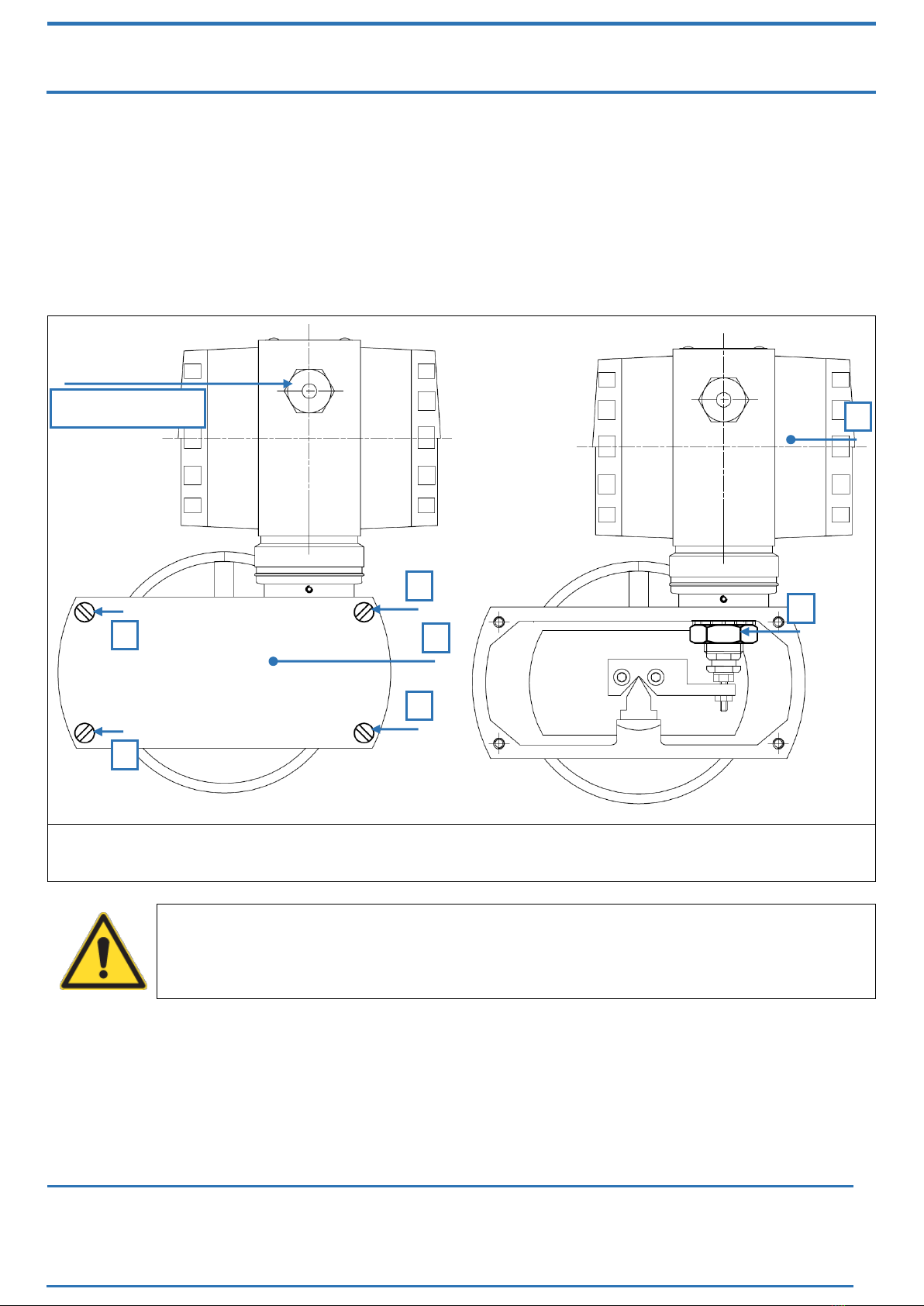
3.7 ELECTRONIC HEAD ORIENTATION
In order to rotate the electronic head in the desired position you must follow these passages
(Figure 7):
unscrew the 4 screws (A) and remove the housing cover (B);
loosen the fixing nut (C) with key CH24 and by hand gently rotate the enclosure (D) in the
desired position;
once the desired position is reached fix the nut (C) again with the same key and remount
the housing cover (B).
Figure 7: rotating the transmitter head
WARNING!
Mount back the housing cover being careful to press the gasket correctly.
A
A
A
A
B
It is NOT necessary to
turn off the supply
C
D

OPERATING MANUAL
MN-SST50
ED-17-09
SPRIANO® TECHNOLOGIES - www.spriano.it –spriano@terranova-instruments.com
a TERRANOVA® Srl brand - www.terranova-instruments.com - VAT IT07848810151
Factory & Sales: Via Gramsci 1 –26827 Terranova dei Passerini (LO) –Italy
Head Office: Via Rosso Medardo 16 –20159 Milano –Italy Ph: +39 0377 919119 –Fax: +39 0377 855720
Pag. 14/48
3.8 ELECTRICAL CONNECTION
Under the rear cap are placed the terminals reporting the electric polarity (Figure 8).
Insert the power supply cable into the enclosure through one of the two threaded openings.
Transmitter is protected from accidental inversion of polarity. For a better use is recommended
a twisted pair cable (22 AWG min). Avoid placing Transmitter near devices powered in AC or
Switching. Connect ground-tap of the Transmitter to the local common earth (PE) as indicated
in Earthing.
WARNING!
The threaded opening that is not used must be sealed using a suitable cap.
The caps included in the delivery are only for protection during transport.
Figure 8: electrical connection
INFORMATION!
Impedance of the cables defines the possible maximum length for digital
communication. It's recommended using cable with a low impedance. The
maximum length of the point to point connection, with a load of 250 ohm and
single twisted cable 22 AWG-207 pF/m it's about 1000 meters.
The maximum connection length for the analog signal only is limited by the loads
(connected devices and cable) present in the current loop.
To obtain output signal of 4-20 mA, you have to determine the minimum supply voltage as a
function of the load relation: see Figure 9. From the following formula you can achieve the
right minimum value of supply voltage:
Vdc = 0.0215xRL+ 12
Where: RL= output load [Ohm].
The power supply source to assure a minimum current value of 24 mA.
Loop
4-20 mA
Loop 4-20 mA
For remote local
indicator SST50-REM
(OPTIONAL)
Ground

OPERATING MANUAL
MN-SST50
ED-17-09
SPRIANO® TECHNOLOGIES - www.spriano.it –spriano@terranova-instruments.com
a TERRANOVA® Srl brand - www.terranova-instruments.com - VAT IT07848810151
Factory & Sales: Via Gramsci 1 –26827 Terranova dei Passerini (LO) –Italy
Head Office: Via Rosso Medardo 16 –20159 Milano –Italy Ph: +39 0377 919119 –Fax: +39 0377 855720
Pag. 15/48
MANDATORY!
In order to obtain a 4÷20 mA + Hart® output a minimum load of 250 Ohm is
required.
TAG
-
1
2
3
4
Vdc
12.5
17.4
24
25.2
30
Ohm
23
250
558
615
837
Figure 9: operating area for Ex ia protection
The electronic transmitters totally comply with the HART® protocol specification Revision 6.0,
so they include remote process variable interrogation, parameter setting and diagnostics.
The device is a 4÷20mA 2-wire transmitter, with FSK communication.
It is possible to read via HART® the following variables:
PV: transmitter main measure;
SV: % of the span;
TV: analog output.
QV: instrument temperature.
Please refer to Figure 10 for the 4÷20 mA + Hart® modem connection.
In Figure 11 the multidrop Hart® connection type is shown.
It is possible to purchase the Hart Server as an additional product; this is a software including all
the interrogation, configuration and diagnostics functions required by the Hart® 6.0
specifications.

OPERATING MANUAL
MN-SST50
ED-17-09
SPRIANO® TECHNOLOGIES - www.spriano.it –spriano@terranova-instruments.com
a TERRANOVA® Srl brand - www.terranova-instruments.com - VAT IT07848810151
Factory & Sales: Via Gramsci 1 –26827 Terranova dei Passerini (LO) –Italy
Head Office: Via Rosso Medardo 16 –20159 Milano –Italy Ph: +39 0377 919119 –Fax: +39 0377 855720
Pag. 16/48
INFORMATION!
Ref. to Figure 10: only one transmitter could be connected to each barrier.
Ref. to Figure 11: up to three transmitters can be connected to each barrier with
a maximum of five Ex ia barriers.
Figure 10: 4÷20 mA + Hart® modem connection with Ex ia barrier
Figure 11: Only Hart® multidrop connection
ATEX
ZONE
NORMAL
ZONE
ATEX
ZONE
NORMAL
ZONE

OPERATING MANUAL
MN-SST50
ED-17-09
SPRIANO® TECHNOLOGIES - www.spriano.it –spriano@terranova-instruments.com
a TERRANOVA® Srl brand - www.terranova-instruments.com - VAT IT07848810151
Factory & Sales: Via Gramsci 1 –26827 Terranova dei Passerini (LO) –Italy
Head Office: Via Rosso Medardo 16 –20159 Milano –Italy Ph: +39 0377 919119 –Fax: +39 0377 855720
Pag. 17/48
Figure 12: DCS connection
MANDATORY!
Transmitter response time is <256ms.
DCS POLLING time must be set approximately at 800ms in order to avoid updating
problems both in analog and digital measurement.
On request the transmitter can be supplied in order to support a Polling time of
500ms but with a minimal consumption of 5 mA.
3.9 INTRINSIC SAFETY PROTECTION
In case of use in areas with danger of explosion, it must be verified that the identified type of
transmitter fits for the classification of the zone and for the presence of flammable substances
in the plant (see MARKING).
The safety essential requisite against the risk of explosion in the classified areas are fixed from
the European Directives 2014/34/EU of 26 February 2014 (as far as it concerns the 'Equipment')
and 1999/92/EC of 16 December 16 1999 (as far as it concerns the 'Working Environment').
WARNING!
For the electrical connections please follow the instructions brought in this
operator manuals taking care that for the use in classified areas it is necessary to
foresee the standard EN 60079-14.
PROHIBITION!
Avoid any ignition hazard due to impact or friction (EN 60079-0:2012 § 8.3).
If the protective guard or any part of the device is damaged by impact or friction,
the type of protection is invalidated.
For the use of the transmitter in hazardous area, you must consider the use of associated
apparatus (barrier), certified according to EN 60079-11, with electrical output compatible with
the maximum input parameters of the transmitter (shown below).

OPERATING MANUAL
MN-SST50
ED-17-09
SPRIANO® TECHNOLOGIES - www.spriano.it –spriano@terranova-instruments.com
a TERRANOVA® Srl brand - www.terranova-instruments.com - VAT IT07848810151
Factory & Sales: Via Gramsci 1 –26827 Terranova dei Passerini (LO) –Italy
Head Office: Via Rosso Medardo 16 –20159 Milano –Italy Ph: +39 0377 919119 –Fax: +39 0377 855720
Pag. 18/48
The evaluation of the system formed by the associated apparatus, the transmitter and the
connecting cables must be performed by experienced personnel and must be in accordance with
the requirements of EN 60079-25 concerning intrinsically safe systems.
For proper installation must take into account the safety instructions of the barrier used.
WARNING!
The choice of the associated apparatus has to be made based on the maximum
input parameters of the transmitter.
Maximum input parameters of the equipment (relative to the intrinsically safety):
Parameter
Tamb
≤ 60°C
Tamb
≤ 80 °C
Output signal
4÷20 mA
4÷20 mA
Input voltage
(V)
30 V
25.2 V
Input current
(li)
100 mA
100 mA
Input power
(Pi)
0.75 W
0.63 W
Internal capacitance
(Ci)
10 nF
10 nF
Internal inductance
(Li)
Negligible
Negligible
INFORMATION!
The device has passed the test of dielectric strength required by the harmonized
standard EN 60079-11. The test has been carried out between the intrinsically safe
circuit and the casing to a voltage of 500V for a time equal to 60s.
The Aluminum housing containing the electronics has passed the tests required by
standard EN 60529 for the degree of protection IP66.
The SS AISI 316 housing containing the electronics has passed the tests required by
standard EN 60529 for the degree of protection IP67.

OPERATING MANUAL
MN-SST50
ED-17-09
SPRIANO® TECHNOLOGIES - www.spriano.it –spriano@terranova-instruments.com
a TERRANOVA® Srl brand - www.terranova-instruments.com - VAT IT07848810151
Factory & Sales: Via Gramsci 1 –26827 Terranova dei Passerini (LO) –Italy
Head Office: Via Rosso Medardo 16 –20159 Milano –Italy Ph: +39 0377 919119 –Fax: +39 0377 855720
Pag. 19/48
3.10 EARTHING
WARNING!
The earth connection is required to prevent damage to people and malfunction of
the instrument.
-Case 1: Installing the instrument in a plant devoid of earthing systems
In the case where the plant devoid of earthing, it is necessary to connect the earth wire to the
terminal block through the cable that carries the signal and the power supply (Figure 8).
-Case 2: Installing the instrument in a plant provided with earthing systems
Make sure the earthing (GND) of the system has the least resistance possible.
You can add an additional earth wire with section not less than 4 mm2 to ensure such
connection.
Figure 13: 4 ÷ 20 mA loop connection with Ex ia barrier
WARNING!
In the case represented in Figure 14, within the earth wire may also scroll through
the current protection of other instruments where the earthing of the system
(GND) had not been carried out in an optimal manner.

OPERATING MANUAL
MN-SST50
ED-17-09
SPRIANO® TECHNOLOGIES - www.spriano.it –spriano@terranova-instruments.com
a TERRANOVA® Srl brand - www.terranova-instruments.com - VAT IT07848810151
Factory & Sales: Via Gramsci 1 –26827 Terranova dei Passerini (LO) –Italy
Head Office: Via Rosso Medardo 16 –20159 Milano –Italy Ph: +39 0377 919119 –Fax: +39 0377 855720
Pag. 20/48
Figure 14: earthing in the housing
WARNING!
The hose must not be considered as a protection against electric shock for the
protection of security, but as protection against electromagnetic interference of
the instrument. Therefore, in the case of long distance cable (L> 20 m), both ends
of the braid must be connected to the chassis or to the connectors. In the case of
cables L <20 meters, will be sufficient to connect the braid only from the side
“Power Supply”.
Figure 15: earthing of the shield for cables longer than 20 meters
This manual suits for next models
9
Table of contents
Other SPRIANO Transmitter manuals


Popular Transmitter manuals by other brands


Dwyer Instruments
Dwyer Instruments 626 Series Installation and operating instructions

Evikon
Evikon PluraSens E2618 Series user manual

Long Range Systems
Long Range Systems T9101 user manual

Trantec
Trantec S6000 instruction manual

HLLY Electronics
HLLY Electronics HLLY TX-01S instruction manual

Furuno
Furuno LH-3000 Operator's manual