SMAR TP303 Manual

,
Profibus Simatic www.esma-rt.ru

web: www.esma-rt.ru
www.esma-rt.ru
Specifications and information are subject to change without notice.
Up-to-date address information is available on our website.
smar

Introduction
III
INTRODUCTION
The TP303 is from the first generation of Profibus-PA devices. It is a transmitter for position
measurements. It can measure displacement or movement of rotary or linear type. The digital
technology and communication provide an easy interface between the field and control room and
several interesting features that considerably reduce the installation, operation and maintenance
costs.
The TP303 is versatile and reliable, and has very high accuracy. It may be used for control valve
stem position measurement, or in any other position sensing application such as louvers, dampers,
crushers, etc.
Since the TP303 uses a non-contact magnetic coupling for position sensing, it less sensitive to
vibration than other solutions, resulting in longer operational life. Deadband due to mechanical
imprecision is avoided. The TP303 mounts to any linear or rotary valve, actuator or a variety of other
devices through the use as VDI/VDE and IEC/NAMUR etc.
The TP303 is very versatile; users can standardize one position indicator for all different kinds of
control valves and other machines, keeping spares and training to a minimum.
The TP303 is part of Smar's complete 303 line of Profibus-PA devices.
Some of the advantages of bi-directional digital communications are known from existing smart
transmitter protocols: Higher accuracy, multi-variable access, remote configuration and diagnostics,
and multi-dropping of several devices on a single pair of wires.
The system controls variable sampling, algorithm execution and communication to optimize the
usage of the network, not loosing time. Thus, high closed loop performance is achieved.
Using Profibus technology, with its capability to interconnect several devices, very large control
schemes can be constructed. In order too be user friendly the function block concept was
introduced.
The TP303, like the rest of the 303 family, has some Function Blocks built in, like Analog Input and
Totalizer Block.
The need for implementation of Fieldbus in small as well as large systems was considered when
developing the entire 303 line of Profibus-PA devices. They have common features and can be
configured locally using a magnetic tool, eliminating the need for a configurator or console in many
basic applications.
The TP303 is available as a product on its own, but also replaces the circuit board for the TP301.
They use the same sensor board. Refer to the maintenance section of this manual for instructions
on upgrading. The TP303 uses the same hardware and housing for the TP302.The TP303 is part of
Smar's 303 Series of Profibus-PA devices.
The TP303, like its predecessor TP301, has some built-in blocks, eliminating the need for a
separate control device. The communication requirement is considerably reduced, and that means
less dead time and tighter control is achieved, not to mention the reduction in cost. They allow
flexibility in control strategy implementation.
Get the best results of the TP303 by carefully reading these instructions.

TP303 - Operation, Maintenance and Instructions Manual
IV
NOTE
This Manual is compatible with version 1.XX, where 1 denotes software version and XX software release. The
indication 1.XX means that this manual is compatible with any release of software version 1.
Waiver of responsibility
The contents of this manual abides by the hardware and software used on the current equipment
version. Eventually there may occur divergencies between this manual and the equipment. The
information from this document are periodically reviewed and the necessary or identified corrections
will be included in the following editions. Suggestions for their improvement are welcome.
Warning
For more objectivity and clarity, this manual does not contain all the detailed information on the
product and, in addition, it does not cover every possible mounting, operation or maintenance
cases.
Before installing and utilizing the equipment, check if the model of the acquired equipment complies
with the technical requirements for the application. This checking is the user’s responsibility.
If the user needs more information, or on the event of specific problems not specified or treated in
this manual, the information should be sought from Smar. Furthermore, the user recognizes that the
contents of this manual by no means modify past or present agreements, confirmation or judicial
relationship, in whole or in part.
All of Smar’s obligation result from the purchasing agreement signed between the parties, which
includes the complete and sole valid warranty term. Contractual clauses related to the warranty are
not limited nor extended by virtue of the technical information contained in this manual.
Only qualified personnel are allowed to participate in the activities of mounting, electrical connection,
startup and maintenance of the equipment. Qualified personnel are understood to be the persons
familiar with the mounting, electrical connection, startup and operation of the equipment or othe
r
similar apparatus that are technically fit for their work. Smar provides specific training to instruct and
qualify such professionals. However, each country must comply with the local safety procedures,
legal provisions and regulations for the mounting and operation of electrical installations, as well as
with the laws and regulations on classified areas, such as intrinsic safety, explosion proof, increased
safety and instrumented safety systems, among others.
The user is responsible for the incorrect or inadequate handling of equipments run with pneumatic
or hydraulic pressure or, still, subject to corrosive, aggressive or combustible products, since thei
r
utilization may cause severe bodily harm and/or material damages.
The field equipment referred to in this manual, when acquired for classified or hazardous areas, has
its certification void when having its parts replaced or interchanged without functional and approval
tests by Smar or any of Smar authorized dealers, which are the competent companies for certifying
that the equipment in its entirety meets the applicable standards and regulations. The same is true
when converting the equipment of a communication protocol to another. In this case, it is necessary
sending the equipment to Smar or any of its authorized dealer. Moreover, the certificates are
different and the user is responsible for their correct use.
Always respect the instructions provided in the Manual. Smar is not responsible for any losses
and/or damages resulting from the inadequate use of its equipments. It is the user’s responsibility to
know and apply the safety practices in his country.

Table of Contents
V
TABLE OF CONTENTS
SECTION 1 - INSTALLATION.................................................................................................................. 1.1
GENERAL...................................................................................................................................................................................1.1
HOUSING ROTATION................................................................................................................................................................1.5
BUS TOPOLOGY AND NETWORK CONFIGURATION.............................................................................................................1.6
INTRINSIC SAFETY BARRIER ..................................................................................................................................................1.7
JUMPER CONFIGURATION ......................................................................................................................................................1.7
POWER SUPPLY .......................................................................................................................................................................1.7
DISASSEMBLY PROCEDURE...................................................................................................................................................1.8
ASSEMBLY PROCEDURE.........................................................................................................................................................1.9
SECTION 2 - OPERATION....................................................................................................................... 2.2
FUNCTIONAL DESCRIPTION – HALL SENSOR.......................................................................................................................2.2
FUNCTIONAL DESCRIPTION – ELECTRONICS ......................................................................................................................2.2
HALL EFFECT SENSOR............................................................................................................................................................2.3
SECTION 3 - CONFIGURATION.............................................................................................................. 3.1
TRANSDUCER BLOCK..............................................................................................................................................................3.1
TRANSDUCER BLOCK DIAGRAM FOR POSITION TRANSMITTER........................................................................................3.1
TRANSDUCER BLOCK PARAMETER DESCRIPTION..............................................................................................................3.2
TRANSDUCER BLOCK PARAMETER ATTRIBUTES................................................................................................................3.4
TRANSDUCER BLOCK VIEW OBJECT.....................................................................................................................................3.5
HOW TO CONFIGURE THE TRANSDUCER BLOCK................................................................................................................3.6
HOW TO CONFIGURE THE ANALOG INPUT BLOCK..............................................................................................................3.7
TP303 CYCLICAL CONFIGURATION........................................................................................................................................3.9
HOW TO CONFIGURE THE TOTALIZER BLOCK...................................................................................................................3.10
LOWER AND UPPER TRIM .....................................................................................................................................................3.12
POSITION TRIM - TP303..........................................................................................................................................................3.13
TEMPERATURE TRIM .............................................................................................................................................................3.14
BACKUP RESTORE.................................................................................................................................................................3.15
TRANSDUCER DISPLAY – CONFIGURATION .......................................................................................................................3.15
DISPLAY TRANSDUCER BLOCK............................................................................................................................................3.16
DEFINITION OF PARAMETERS AND VALUES.......................................................................................................................3.16
PROGRAMMING USING LOCAL ADJUSTMENT ....................................................................................................................3.19
SECTION 4 - MAINTENANCE PROCEDURES........................................................................................ 4.1
GENERAL...................................................................................................................................................................................4.1
DISASSEMBLY PROCEDURE...................................................................................................................................................4.2
TRANSDUCER ...........................................................................................................................................................................4.2
REASSEMBLY PROCEDURE....................................................................................................................................................4.3
ELECTRONIC CIRCUIT..............................................................................................................................................................4.3
UPGRADING TP301 TO TP303 .................................................................................................................................................4.3
SECTION 5 - TECHNICAL CHARACTERISTICS .................................................................................... 5.1
FUNCTIONAL SPECIFICATIONS ..............................................................................................................................................5.1
PERFORMANCE SPECIFICATIONS..........................................................................................................................................5.1
PHYSICAL SPECIFICATIONS....................................................................................................................................................5.2
ORDERING CODE......................................................................................................................................................................5.2
APPENDIX A – SRF – SERVICE REQUEST FORM................................................................................A.1
RETURNING MATERIALS......................................................................................................................................................... A.2
APPENDIX B – SMAR WARRANTY CERTIFICATE ...............................................................................B.1

TP303 - Operation, Maintenance and Instructions Manual
VI
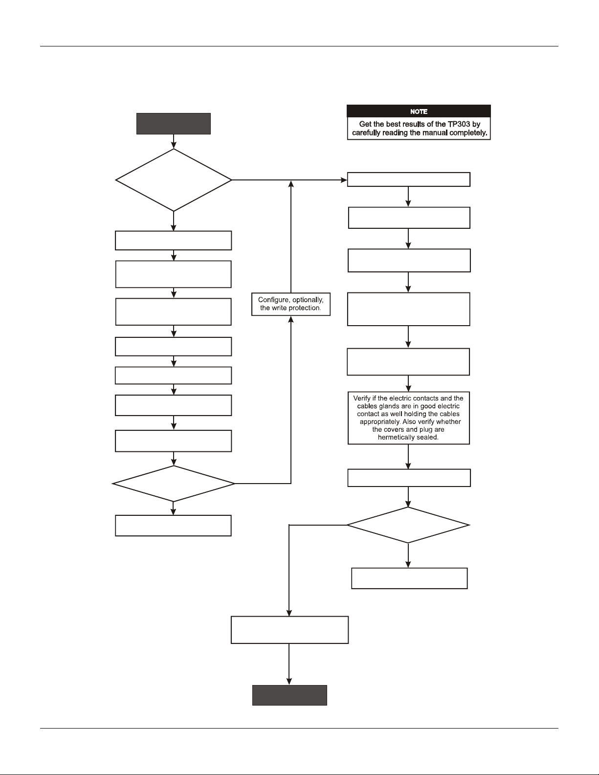
Table of Contents
VII
I
nsta
ll
at
i
on
Fl
owc
h
art
Quick Installation Guide
Has the transmitter
been configured
in bench for the
application ?
Configure the transmitter
( section 1 and section 3).
Start
Field Installation.
Install the transmitter in
protected areas.
Install the transmitter (mechanically
and electrically) according to the
application, verifying the most
appropriate position of the LCD.
Verify area classification and
its respective practices.
NO
YES
Configure Fail Safe value
(Section 3).
Configure Damping (Section 3).
Configure the indication in LCD
(Section 3).
Configure the user unit in case
of specific measurements.
Is the measurement
OK ?
NO
YES
Is ?
the
measuring ok
OK
NO
Using the GSD file, configure
the cyclic data in the system
configuration tool (Section 3)
YES
Consult the manual
Section 4 - Maintenance.
Consult the manual
Section 4 - Maintenance.
Dislocate the system to
upper position, execute the
upper position trim for 100%.
Dislocate the system to
lower position, execute the
lower position trim for 0%.
Power the transmitter appropriately.
Fix the transmitter magnet
in a position that allows to the
sensor to travel all magnet range.

TP303 - Operation, Maintenance and Instructions Manual
VIII

Section 1
1.1
INSTALLATION
The overall accuracy of measurement and control depends on several variables. Although the
converter has an outstanding performance, proper installation is essential, in order to maximize its
performance.
Among all factors, which may affect converter accuracy environmental conditions are the most
difficult to control. There are, however, ways of reducing the effects of temperature, humidity and
vibration.
In warm environments, the transmitter should be installed to avoid, as much as possible, direct
exposure to the sun. Installation close to lines and vessels subjected to high temperatures should
also be avoided.
Use of sunshades or heat shields to protect the transmitter from external heat sources should be
considered, if necessary.
Humidity is fatal to electronic circuits. In areas subjected to high relative humidity, the O-rings for the
electronics cover must be correctly placed. Removal of the electronics cover in the field should be
reduced to the minimum necessary, since each time it is re-moved; the circuits are exposed to the
humidity. A humidity proof coating protects the electronic circuit, but frequent exposures to humidity
may affect the protection provided. It is also important to keep the covers tightened in place. Every
time they are re-moved, the threads are exposed to corrosion, since painting cannot protect these
parts. Code approved sealing methods on conduit entering the transmitter should be employed.
Although the transmitter is virtually insensitive to vibration, installation close pumps, turbines or
other vibrating equipment should be avoided.
General
MOUNTING
The mounting of transmitter TP303 will depend on type movement, if it is linear or rotary. Two
supports are required for mounting, one for the magnet and the other for the transmitter itself. Smar
may supply then both since they are specified in the order code (See page 4.7)
Rotary Movement
Install the magnet on the valve stem using the magnet support (See figure 1.2). Install the
transmitter support on the actuator. Should the actuator be in accordance with standard VDI/VDE
5845, all you have to do is tighten the four screws with the lock washers on the standard support.
For special supports, refer to specify instructions. After installing the support on the actuator, it is
possible to mount transmitter TP303 on the support by means of the four screws with lock washers.
Make sure that the arrow engraved on the magnet coincides with the arrow engraved on the
transmitter when the system is in mid travel. In case the installation of the transmitter or magnet is
altered, or should there be any other modification, the transmitter will require a recalibration.
Linear Movement
Install the magnet on the valve stem using the magnet support (See figure 1.3). Install the
transmitter support on the actuator. The actuator support may be secured in place as per standard
NAMUR/IEC 536-4 or in accordance with user specified boring. Install the transmitter on the support
and tighten the four screws in the threaded bores located on the side opposite to the sensor (Figure
1.3). Use lock washers in order to prevent screw slackening.
Make sure that the support is not obstructing the exhaustion outlets.

TP303 - Operation, Maintenance and Instructions Manual
1.2
NOTE
Make sure that arrow engraved on the magnet coincides with the arrow engraved on the position transmitter
when the system is in mid travel. The magnet mounting in relation to the hall sensor:
1 . Must not have attrict between the internal magnet face and the hall sensor salience during the travel
(rotary or linear), through the magnet.
2. The magnet and the salience of hall sensor must not be distant.
A minimum distance of 2mm and a maximum distance of 4mm is recommended between the magnet external
face and the position transmitter face.
Should the installation of the transmitter or magnet be altered, or should there be any other
modification, the transmitter will require a re-calibration.
Installation
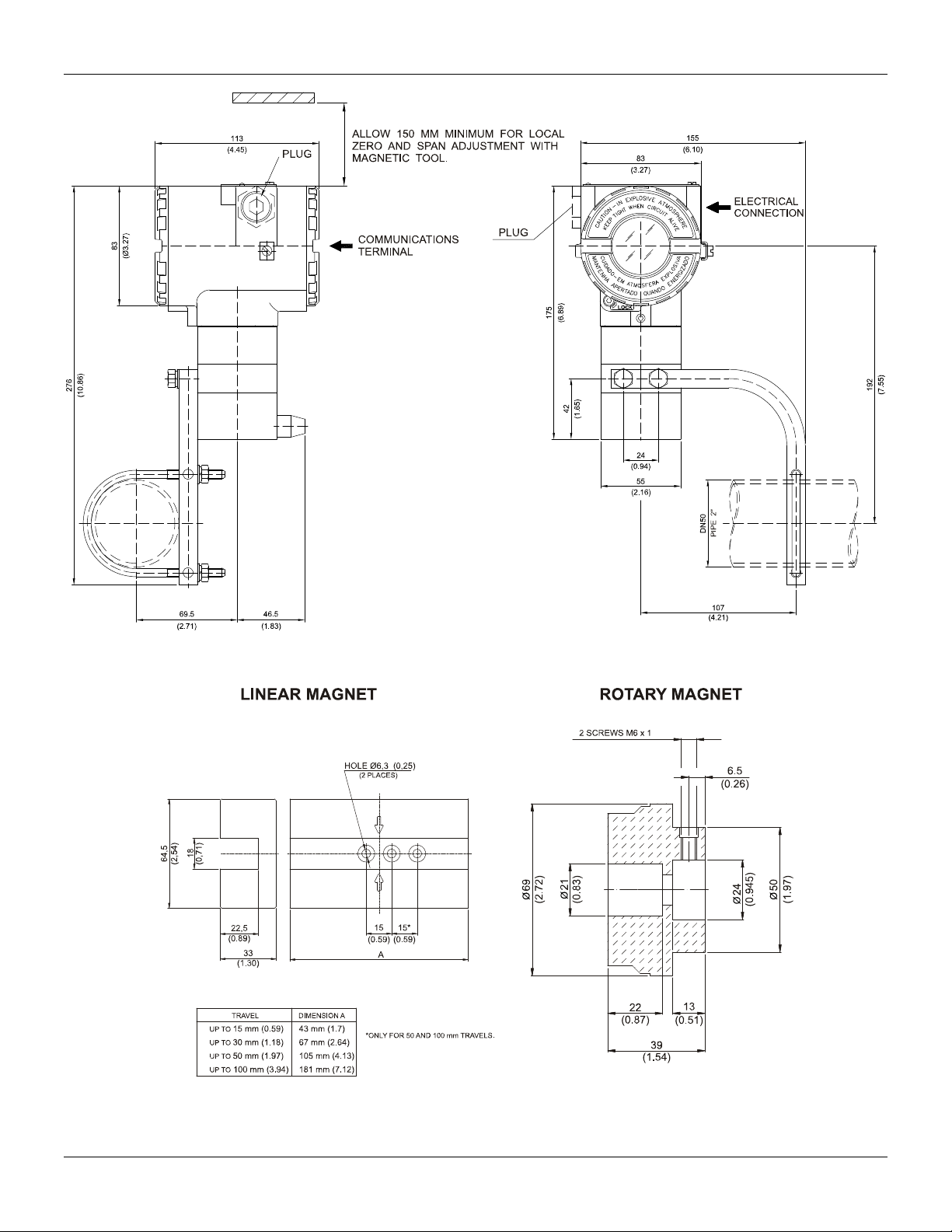
1.3
Figure 1.1 – TP303 and Magnet Dimensional Drawing
TP303 - Operation, Maintenance and Instructions Manual
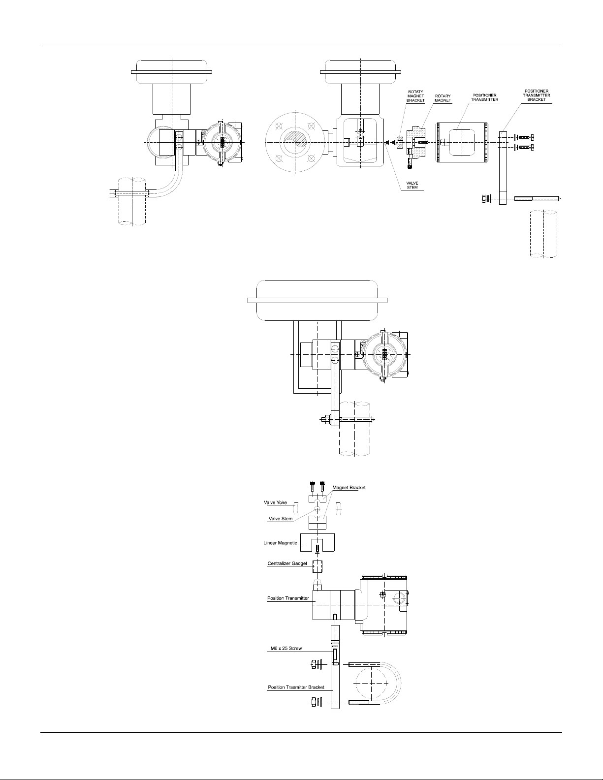
1.4
Figure 1.2 – Transmitter on the Rotary Actuator
Figure 1.3 – Transmitter on the Linear Actuator

Installation
1.5
Housing Rotation
The electronic housing can be rotated in order to better position the digital display. To rotate it, uses
the housing rotation set screw, see figure 1.4.
The local indicator itself can also be rotated. See section 5, figure 5.2.
Electric Wiring
Reach the wiring block by removing the electrical connection cover (figure 1.4). This cover can be
locked closed by the cover locking screw. To release the cover, rotate the locking screw clockwise.
Figure 1.4 – Cover Locking and Housing Rotation Set Screw
The wiring block has screws on which fork or ring-type terminals can be fastened. See figure 1.5.
For convenience there are two ground terminals: one inside the cover and one external, located
close to the conduit entries.
Figure 1.5 – Wiring Block
The TP303 uses the 31.25 kbit/s voltage mode option for the physical signaling. All other devices on
the same bus must use the same signaling. All devices are connected in parallel along the same
pair of wires.
Various types of Fieldbus devices may be connected on the same bus.
The TP303 is powered via the bus. The limit for such devices is according to DP/PA coupler
limitations for one bus for non-intrinsically safe requirement.
In hazardous area, the number of devices may be limited by intrinsically safe restrictions, according
to the DP/PA couples and barriers limitations.
The TP303 is protected against reverse polarity, and can withstand ±35 VDC without damage, but it
will not operate when in reverse polarity.
TP303 - Operation, Maintenance and Instructions Manual
1.6
WARNING
HAZARDOUS AREAS
In hazardous zones with explosion proof requirements the covers must be tightened with at least 7 turns. In
order to avoid moisture or corrosive gases, hand tighten the covers until the O-rings are compressed. Lock the
covers closed with the locking screw.
In hazardous zones with intrinsically safe or non-incentive requirements, the circuit entity parameters and
applicable installation procedures must be observed.
Cable access to wiring connections is obtained by the two conduit outlets. Conduit threads should be sealed by
means of code-approved sealing methods. The unused outlet connection should be plugged and sealed
accordingly.
Should other certifications be necessary, refer to the certification or specific standard for installation limitations.
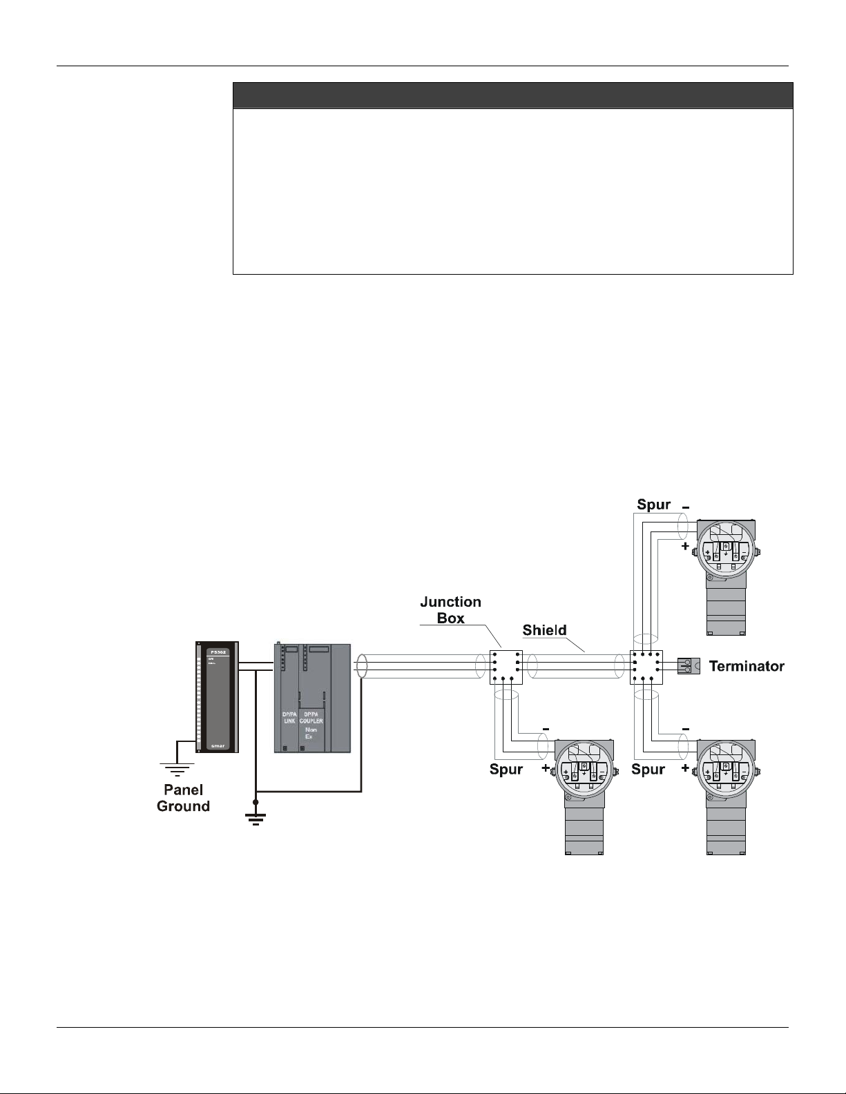
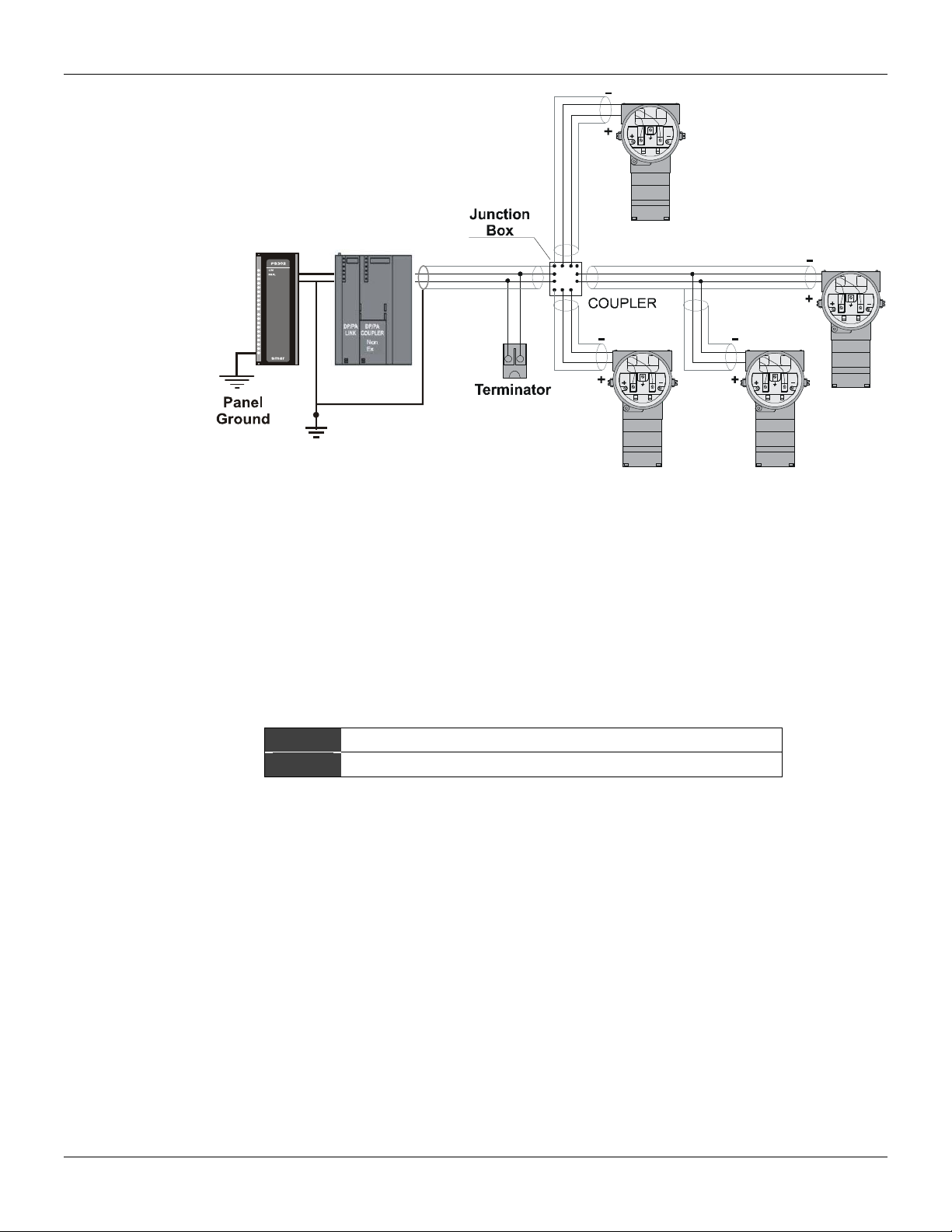
Bus Topology and Network Configuration
Bus and tree topology are supported. Both types have a trunk cable with two terminations. The
devices are connected to the trunk via spurs. The spurs may be integrated in the device giving zero
spur length. A spur may connect more than one device, depending on the length. Active couplers
may be used to extend spur length.
Active repeaters may be used to extend the trunk length.
The total cable length, including spurs, between any two devices in the Fieldbus should not exceed
1900m.
In following figures, the DP/PA link depends on the application needs.
Analog
Ground
+
-+
-
Figure 1.6 - Bus Topology
Installation
1.7
Analog
Ground
+
-+
-
Figure 1.7 - Tree Topology
Intrinsic Safety Barrier
When the Fieldbus is in an area requiring intrinsic safety, a barrier must be inserted on the trunk
between the power supply and the DP/PA coupler, when it is Non-Ex type.
Use of DF47 is recommended.
Jumper Configuration
In order to work properly, the jumpers J1 and W1 located in the TP303 main board must be correctly
configured.
J1 This jumper enables the simulation mode parameter in the AI block.
W1 This jumper enables the local adjustment-programming tree.
Table 1.1 - Description of the Jumpers
Power Supply
The TP303 receives power from the bus via the signal wiring. The power supply may come from a
separate unit or from another device such as a controller or DCS.
The voltage should be between 9 to 32 Vdc for non-intrinsic safe applications.
A special requirement applies to the power supply used in an intrinsically safe bus and depends on
the type of barrier used.
Use of PS302 is recommended as power supply.
Remote Hall Sensor
The remote Hall magnetic sensor is recommended for applications where there are high
temperatures and extreme vibrations applications. It prevents excessive wear of the equipment and,
consequently, the reduction of its useful lifetime.
TP303 - Operation, Maintenance and Instructions Manual
1.8
The electric signals on the remote sensor’s connection cable are of low intensity. Therefore, it is
recommended to install the cable inside a conduit (maximum length 20 meters) away from possible
sources of induction and/or electromagnetic interferences. The cable supplied by Smar is shielded
in order to protect it against electromagnetic interferences. Despite this protection, it is not
recommended for the cable to share the same conduit with other cables. The parts for the sensor’s
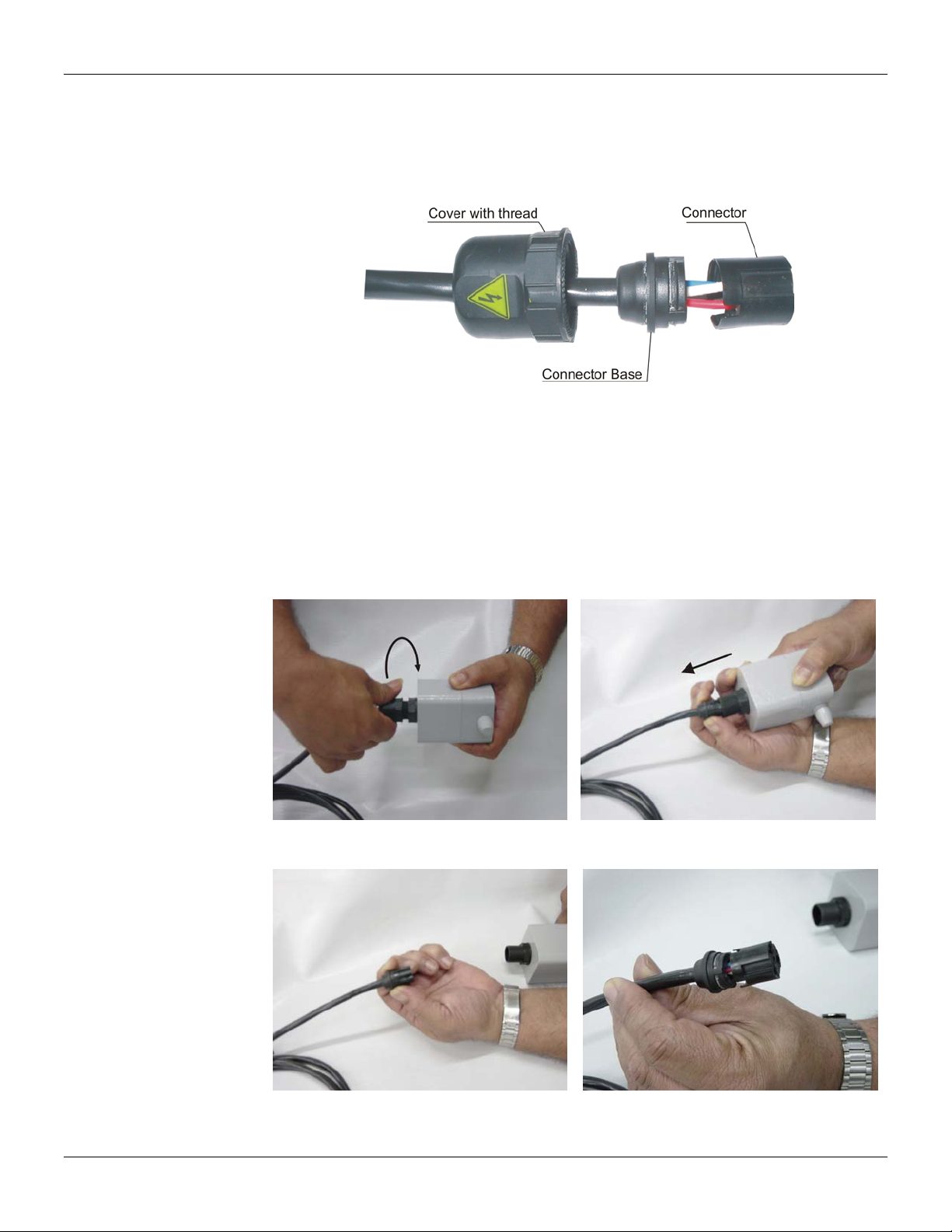
connection cable are:
Figure 1.08 – Hall Sensor Cable and Accessories
Disassembly Procedure
Figures 1.09 to 1.12 show the correct disassembling order for the Hall sensor. The steps for
disassembling are:
1. Unscrew the cover, by turning it on counter-clockwise direction (direction of the arrow) for the
remote Hall side according to figure 1.09.
2. Pull the cable following the arrow as in figure 1.10,
3. Pull the cable connector base, to release it from the block connector, according to figures 1.11
and 1.12.
Figure 1.09 – Disconnecting the cover of
the Hall sensor cable Figure 1.10 – Disconnecting the Hall
sensor cable
Figure 1.11 – Unfastened Connector
Figure 1.12 – Connector with the cable’s
wires maintained in their orifices

Installation
1.9
Figure 1.13 – Wires position in the connector Figure 1.14 – Release the cables’ connector
Assembly Procedure
Mount the components following the sequence:
1. Pass the cable through the cover orifice (Figure 1.15);
2. Pass the cable through the base connector orifice (Figure 1.16);
3. The red, white, and black wires should be inserted in the base connector orifice marked by
numbers beside them, look at figure 1.17 e 1.18.
Figure 1.15 – Assembling the cover Figure 1.16 – Assembling the wire bracket
Orifice to the
white cable Orifice to the
red cable
Orifice to the
black cable
Figure 1.17 – Inserting the wires in the
connector Figure 1.18 – Orifice Cable’s Connector with
numbers beside them
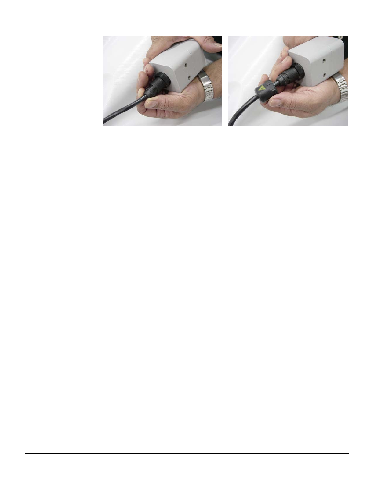
Insert the cable connector in the remote Hall's block connector as figure 1.19. The block connector
has internal saliencies that perfectly fit the groove, in order to prevent errors in the assembly. The
cutting pins inside of the block connector will cut the wire insulators and press against them, thus
establishing the electric contact between the cable and the hall sensor’s circuit.
To finish, fasten the cover to the Hall sensor’s connection (figure 1.20).
TP303 - Operation, Maintenance and Instructions Manual
1.10
Figure 1.19 – Fasten the cover to the remote
Hall Figure 1.20 – Assembly finished
Section 2
2.1
OPERATION
Functional Description – Hall Sensor
Sensor Hall supplies an output voltage proportional to the applied magnetic field. This magnetic
sensor is ideal for use in system of sensor of linear or rotative position. The mechanical vibrations
do not affect Sensor Hall.
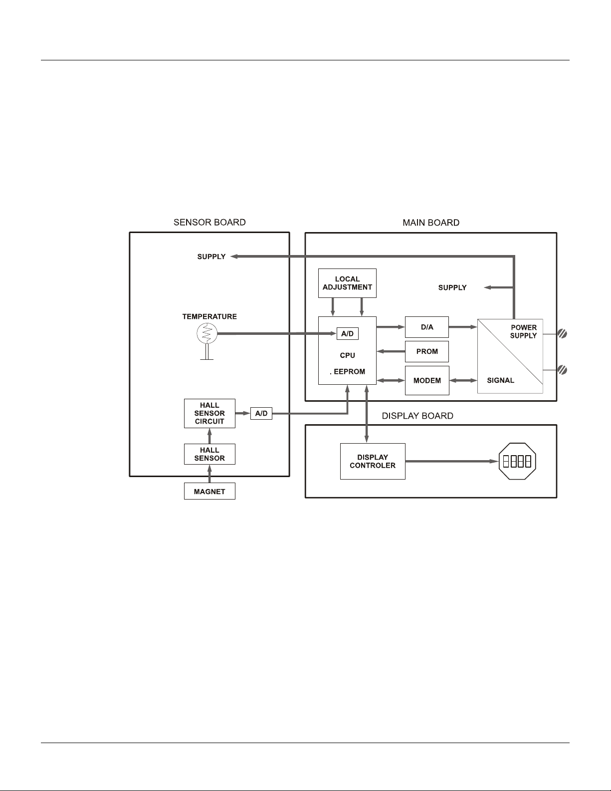
Functional Description – Electronics
Refer to the block diagram. The function of each block is described below.
Figure 2.1 - TP303 Block Diagram Hardware
Oscillator
This oscillator generates a frequency as a function of sensor capacitance.
Signal Isolator
The control signals from the CPU and the signal from the oscillator are isolated to avoid ground
loops.
Central Processing Unit (CPU), RAM, FLASH and EEPROM
The CPU is the intelligent portion of the transmitter, being responsible for the management and
operation of measurement, block execution, self-diagnostics and communication. The program is
stored in a flash memory for easy upgrade and saving data on power-down event occurrence. For
temporary storage of data, there is a RAM. The data in the RAM is lost if the power is switched off,
however the main board has a nonvolatile EEPROM memory where the static data configured that
must be retained is stored. Examples of such data are the following: calibration, links and
identification data.
Fieldbus Modem
Monitors line activity, modulate and demodulate communication signals; inserts and deletes start
and end delimiters, and check integrity of frame received.
TP303 - Operation, Maintenance and Instructions Manual
2.2
Power Supply
Takes power of the loop-line to power the transmitter circuitry.
Power Isolation
Isolates the signals to and from the input section, the power to the input section must be isolated.
Hall Effect Sensor
Measures the position actual to the CPU.
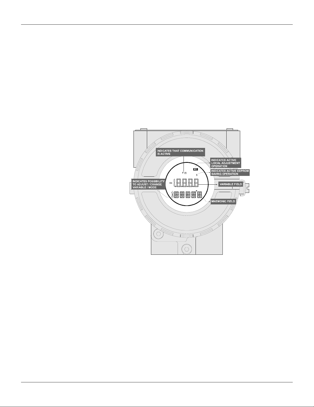
Display Controller
Receives data from the CPU identifying which segments on the liquid crystal display use to turn on.
The controller drives the backplane and the segment control signals.
Local Adjustment
There are two switches that are magnetically activated. The magnetic tool without mechanical or
electrical contact can activate them.
Figure 2.2 - LCD Indicator
Table of contents
Other SMAR Transmitter manuals


Popular Transmitter manuals by other brands

Intercoax
Intercoax Ipify ECP-2704R-4T-PKG Quick install guide

Velleman
Velleman VM121 manual

Air Monitor
Air Monitor ELECTRA-flo G5 Installation and operation manual

RF Central
RF Central RFX-NLL Operator's manual

AMG
AMG AMG4783E-DR-SF instruction manual

Broadcast Warehouse
Broadcast Warehouse TX 25/50 Technical manual


