Poolspa Octavia Installation and operating instructions

Shared SPA Bath
public version
assembly and operation manual

2
Dear Customer,
Thank you for the confidence expressed in buying our product. We have tried hard to make a product which entirely
meets your expectations
For many years we have offered the highest world quality products. We pay particular attention to the durability, reliability
and safety of our products. The highest quality of materials used, interesting styling and ergonomics guarantee that you
will bathe in comfort.
We wish you satisfaction with our products.

3
CONTENTS
I. GENERAL INFORMATION ...........................................................................................................................................4
II. TECHNICAL DRAWINGS.............................................................................................................................................4
1. SAFETY RULES ..........................................................................................................................................................7
2. INSTALLATION PLACE PREPARATION ...................................................................................................................8
3. INSTALLATION OF SPA BATH AND ACCESSORIES................................................................................................8
4. ELECTRICAL CONNECTION ......................................................................................................................................8
5. WATER CONNECTIONS.............................................................................................................................................9
6. SPA BATH FILLING AND EMPTYING .........................................................................................................................9
7. VENTILATION ............................................................................................................................................................ 11
8. FROST PROTECTION .............................................................................................................................................. 11
9. SPA BATH MASSAGE SYSTEM ............................................................................................................................... 11
10. WATER FILTRATION SYSTEM................................................................................................................................ 11
11. HEATER AND LIGHTING .........................................................................................................................................12
12. CONTROL SYSTEM ................................................................................................................................................12
13. ACRYLIC COATING MAINTENANCE......................................................................................................................15
14. GENERAL INFORMATION ABOUT THE MEASURING EQUIPMENT ....................................................................16
15. TECHNICAL DATA ...................................................................................................................................................16
16. SAFETY....................................................................................................................................................................18
17. INSTALLATION ........................................................................................................................................................18
18. OPERATION.............................................................................................................................................................20
19. CALIBRATION..........................................................................................................................................................27
20. MAINTENANCE .......................................................................................................................................................28
21. TROUBLESHOOTING .............................................................................................................................................29
GUARANTEE CONDITIONS..........................................................................................................................................30
TECHNICAL PRODUCT SHEET....................................................................................................................................31

4
This instruction contains information necessary for the installation and use of the SPA bath. Before starting hydromassage
please read all chapters carefully.
The SPA bathtub is intended for public use.
I. GENERAL INFORMATION
AIR MASSAGE:
- Blower 1,3 kW 1 x 230 V.
- Air holes at the bottom and the seats of the SPA bathtub.
WATER MASSAGE:
- hydromassage pump 2.0 kW (Olivia, Sunflower or an option with 32 jets - 2 pumps)
- filtration pump 2.65 kW
- jets: 6 - 32 pieces depending on the model
- air regulators
WATER FILTRATION AND HEATING:
- Sand filter diameter 1200 mm,
- UV lamp (option)
- 9 kW heater with flow rate measurement and heating intensity (Olivia, Sunflower – 12 kW), optionally, pipe
water-water heat exchanger 44 kW
UNDERWATER LED LAMP or multi-point LED lighting
CHARACTERISTICS:
- SPA bathtubs capacities:
Janette: 900 litrów Vesta: 1600 litrów
Octavia: 1050 litrów Olivia: 2100 litrów
Victoria: 1100 litrów Sunflower: 2000 litrów
Classic: 1400 litrów Olimpia: 2000 litrów
Natalie 1300 litrów
II. TECHNICAL DRAWINGS
Janette Octavia
610
700
1665
2150
590
650
1485
1970
1235
1415
330
1020
275
540
780
155
40
1685
1620
650
500
2260
160
690
890
400
190
430
930
50
1080 20
80 200 40
130

5
Victoria Classic
2490
1800
1580
655
545
240
620
850
105 240 105
160
455
310
50
380
1080 20
570
800
2280
630
845
1020
375
170
40 1750
1860
2340
500
640
1930
2610
2040
600
770
235
225
90 190 55
130
Natalie Vesta
195
540
765
1020
330
140
200
85 105
40
1740
1950
2525
1045
310 780
975
360
170
540
810
1110
305
45
1200
2100
2300
2900
850
1070
300
540
135
200
100 95

6
SunflowerOlivia
2830
2280
2200
805
1050
250
1270
50
1160 20
430
900
640
160
130
200
80 40
1935
2490
900
400
210
690
910
330
1000
1150
300
2425
2990
750
50
1113 20
125
195
85 55
1900
2500
1900
2500
700
740
560
280
1700
1690
650
700
180
40
930
1160
380
145
200
Olimpia

7
- Tank capacity: 1100 litre
- Tank dimensions: 1400 x 700 x 1400 mm
- Number of people: 3-8 depending on the model
- Electrical supply: 3 x 400 V
- Maximum Power Consumption ~15 kW (Olivia, Sunflower ~20 kW)
- Machine room palettes:
• palette with filtration pump, heater, UV lamp (according to the client’s order): 1590 x 1280 mm, weight approx. 111 kg
• palette with blower and water pump: 700 x 700 mm, weight approx. 46 kg
• palette only with water pump - additional (for Olivia, Sunflower bathtubs and with the option with 32 jets): 600 x 400
mm, weight 15.5 kg
1. SAFETY RULES
The SPA bath will be supplied to the customer in its original packaging. After the package is removed and before starting
the installation, the SPA bath should be carefully checked. The manufacturer’s service should be informed about any
abnormalities found.
Do not raise the bath and filtering equipment when holding their piping elements.
Always put the bath on its legs, do not prop it on its side.
Ensure that the bath is properly protected during installation works in its close vicinity.
Connection of the bath electrical system to power network and execution of water connections should be performed by
authorized installers.

8
2. INSTALLATION PLACE PREPARATION
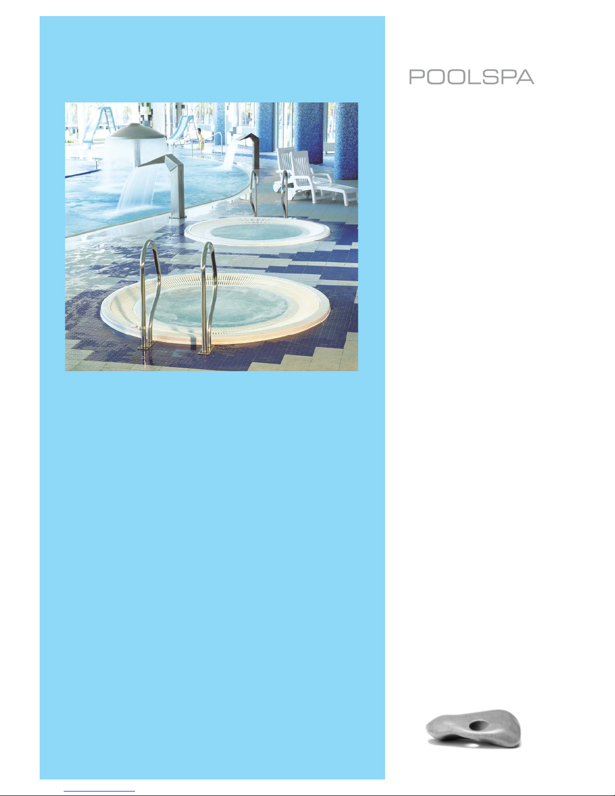
- The SPA bath can operate in both closed and open spaces.
- The SPA bath should be installed on a hard substrate to avoid equipment settlement.
- When the SPA bath is located in a closed space, enough space should be provided to carry the equipment in.
- Dimensions of a foundation plate on which the SPA bath is to be installed should be large enough to enable proper
arrangement of legs, conduits and cables.
- A method of the SPA bath emptying should be kept in mind. The substrate must be leveled.
- Note also walls and ceiling material. They should be resistant against water vapour volatizing during the SPA bath operation.
- Because of water splashing during SPA bath use, its substrate must be made of highly water-resistant material, such
as glace or plastic coatings. Floor finish must be appropriately protected against bacteria breeding in a wet environment.
Special rugs or floor finishes applied in sailing should be used. Parquet or other wooden floor are not recommended,
unless they were subjected to an appropriate processing like wood used for gardening or outdoor constructions. Ensure
that the floor hydraulic gradient towards the local floor sewer inlet is 2%.
3. INSTALLATION OF SPA BATH AND ACCESSORIES
- Proper SPA bath operation requires its installation on a durable and carefully leveled substrate, e.g. on 10 cm thick
concrete plate, to avoid equipment settlement.
- Weight of the fully water-filled SPA bath with 3 bathing persons amounts to about 1200 kg. The pressure exerted on
the substrate amounts to 360 kg/m2.
- After the bath installation height is set, a concrete block on which both stationary and telescopic legs will lean should
be prepared.
- Pit and concrete block dimensions should be large enough for proper placement of legs, piping and cables.
- After telescopic legs are installed, bath crown should be leveled.
- Fasten legs to the concrete block in such a way they are not able to move accidentally.
- All connections of accessories to the bath should be made of glue-joined pipes and fittings. Do not use metal pipes
and components.
- After the bath is filled with water check joints and connections for their leakproofness.
- Do not fill the space around the bath with any material. Access to all pipes and connections should be ensured.
- Accessories should be installed very carefully. It is the best to install them in an air-conditioned space and in a distance
to the bath not exceeding 10 m horizontally. Height of foundation plate on which accessories are installed should not be
bigger than that of the bath foundation plate. Also, accessories should not be installed more than 2,5 m below the bath
level. When distances are larger consult manufacturer service.
- It is advisable to locate a floor sewer inlet within the bath installation area and below its level.
4. ELECTRICAL CONNECTION
Electrical system connection to the power network should be performed by an authorized electrician.
Internal connections of accessories are factory-made.
The SPA bath electrical system should be protected with balanced-current circuit breaker with 30 mA rated
switch-off value, as well as with 40 A magnetic - thermal circuit breaker equipped with all poles disconnection
mechanism and at least 3 mm opening distance. Both circuit breakers should be located outside safety
zones marked on Figure 1.
4.1. Grounding
Proper operation of balanced-current circuit breaker requires a grounded system according to provisions in force, as
well as equalizer connections installed in the apartment.
4.2. Feeder cable location
The SPA bath feeder cable should be permanently connected to the electrical network, in no case through a wall socket.
Electrical system should be made according to the requirements for low voltage systems in force. Therefore it is impor-
tant to have in mind that the SPA bath installation creates 4 safety zones as shown in Figure 1. So, the feeder cable
should be located in zone 3 or on an suspended ceiling more than 2.25 m overhead.
4.3. Power supply connection
When connecting the power supply, note that:
- The SPA bath electrical power supply should be permanently connected to the power network.
-Cable used should fulfill appropriate low voltage system requirements. It should be remembered that yellow-green
grounding wire should be at least 40 mm longer than phase and neutral wires so as to be disconnected as the last one
in case of violent pulling.
- Power supply connection under the SPA bath can be made only when at least IPX5 protection level is ensured and the
connection is at least 20 cm above the floor.

9
Figure 1.
2,4 m
2,4 m
Zone 1Zone 1
Zone 0
Zone 3 Zone 3
Zone 2
Zone 2
2,25 m
0,6 m 0,6 m
Very important: Ensure total tightness (IPX5 level) of electrical connections.
5. WATER CONNECTIONS
Use PVC conduits and appropriate glue for water connections. Do not use metal pipes.
Ensure that there are no air plugs or water in the SPA bath filling and emptying connection. Emptying the system
should ensure excellent SPA bath emptying. When the water outlet state enables it, the water trap can be installed to
avoid an unpleasant smell.
Moreover, install the return valve in filling and emptying system to avoid reverse water flow,.
All bath and accessory connections are successively numbered. Joining the bath and accessory components should be
based on their numbers. Installation of valves between each joint and accessory is recommended, so as to facilitate the
preparation for maintenance works – then the SPA bath emptying is not required.
To avoid reverse water flow, blower PVC pipe should be located at least 30 cm above the upper SPA bath crown
After the installation is finished, switch the equipment ON and check connections tightness. Mark water level in
the bath and after 24 hours check if it did not drop.
Check if the motor rotates in proper direction. If not, change phase wires on its terminals.
Check if the pressure in nozzles is correct. In case of gridlock remove its cause and then put the bath into its final position.
6. SPA BATH FILLING AND EMPTYING
Never use air blower system for the SPA bath filling.
The SPA bath can be connected to the water-pipe network permanently or through separable, flexible conduit installed
to fill in the SPA bath only.
Filling the SPA bath is made through ½” pipe (point b) located in the SPA-bath nozzle conduit.
The SPA bath drain must be connected to the compartment or apartment (point a) sewerage system. To avoid unplea-
sant smell, use of a water plug is recommended.

10
Figure 2. SPA baths - gutter (connection).
spust wody z kanałów
water drainagefrom channels
z pompy 2- 63 mm zasilanie hydromasażu
from pump 2- 63 mm hydromassageaspiration
z pompy 1- 63 mm zasilanie hydromasażu
from pump 1- 63 mm hydromassageaspiration
dopompy-63 mm zassanie hydromasa2 żu
to pump 2- 63 mm hydromassageaspiration
z dmuchawy -
zasilanie50 mm
from theblower -
50 mm supply
z filtra - 63 mm powrótfiltracji
from filter - 63 mm filtration return
odpływrynny - 110 mm
channel outlet - 110 mm
dopompy filtracji- 63 mm
to filtration pump - 63 mm
dopompy-63 mm zassanie hydromasa1 żu
to pump 1- 63 mm hydromassageaspiration
odpływrynny - 110 mm
channel outlet - 110 mm
przelew awaryjny
emergency overflow
nape nianie zbiornikawodął
filling thewater tank
dokanalizacji
to sewagesystem

11
7. VENTILATION
High water temperature (400C max) in the SPA bath causes emission of large water vapour amounts.
Vapour condenser installation is recommended in a compartment where the SPA bath is installed. The effective venti-
lation should be ensured so as to keep air humidity on the same level and to avoid vapour condensation on the ceiling
and floor.
If the compartment contains wooden elements air RH should not be higher than 65% to ensure their proper maintenance.
Air humidity can be kept constant using humidistat-controlled fans or dehumidifiers appropriate for compartment size.
Ask their distributors or fitters for advice. No vapour condenser is necessary when air condition is installed. Similarly,
vapour condenser are superfluous when the SPA bath is located outdoors or in an open compartment.
8. FROST PROTECTION
When SPA bath is installed outdoors, winter brings a risk of freezing. The following recommendations should be considered:
- When a case of heating system malfunction due to outdoor conditions is found, the bath, pipes, the pump and filters
must be completely emptied. Otherwise pipes can break due to ice expansion during the solidification process.
- Hot water cannot be used to thaw pipes or the bath Sudden temperature change can destroy the material they are
made of. Frozen parts must thaw out at room temperature.
- When there is a likelihood that some frozen water still remains within the system do not start the pump nor the blower.
- Do not turn valves if suspected frozen. Otherwise valves can be destroyed and the system unsealed due to ice expan-
sion during solidification.
- Ask equipment fitter for a permanent heating system installation possibility.
- If the heater is to be switched permanently ON, ask equipment fitter about the frost detectors installation possibility, so
as to avoid consequences of power supply failure or heater and/or filtration pump switch off.
- Do not use any antifreeze liquids without appropriate sanitary guarantees.
9. SPA BATH MASSAGE SYSTEM
The SPA bathtub has two massage systems: water and air.
The water massage system is composed from the following elements:
- A set of 6-32 water and air jets that lead water or a mixture of water and/or air to the SPA bathtub water space,
- The filtration pump and the hydromassage pump that forces water movement in the entire water circulation until it
reaches the middle of the SPA bathtub.
- Water aeration regulators (Venturi) installed on the top edge of the SPA bathtub ad used to set the aeration degree of
the water.
- Water aspirator.
The air massage system consists of approx. 100 small holes using which the r is blown into the middle of the SPA
bathtub.
10. WATER FILTRATION SYSTEM
The filtration circuit includes the following elements:
- Overflow duct with a duct covering grate and an overflow tank
- Filtration pump
- Six-function valve
- Water filter.
- Water aspirator.
- PVC pipes and fittings.
10.1. Overflow duct and tank
The overflow duct is an integral part of a SPA type bathtub and is used to lead water from the bathtub to the balance
tank connected together with the pipe of 110 mm diameter. The grate that covers the overflow duct protects the filtration
system against larger foreign bodies and has a decorative function.
The overflow tank is used to gather water pushed upwards by bathing people. A standard capacity overflow tank
(1100 l), suitable for all SPA bathtubs with overflow ducts manufactured by POOL-SPA is installed in the machine room.
In the place of installation of the balance tank, a sewage terminal needs to be prepared, diameter. 63 mm (safety tank
overflow). The overflow tank is equipped with water level sensors, a stream gauge and the following terminals:
- inlet to the tank, diameter 110 mm in top or side wall,
- outlet, diameter 63 mm in the bottom or side wall,
- safety overflow, diameter 63 mm placed in the top part of one of the side walls.
10.2. Maintenance of the filtration pump
Filtration pump is equipped with a crude air purification filter in the form of a basket placed in the pump aspiration
chamber that stops thick contamination and foreign objects (e.g. hair).
Gathering large amounts of contamination in the aspiration basket makes water circulation worse. Remaining in that

12
sate may lead to electric heater damage due to overheating, caused by too low water flow rate. In order to clean the
aspiration basket, perform actions like before cleaning the filter, disassemble the filtration pump cover and remove
contamination gathered in the basket.
10.3. Six-function valve
A six-function valve is used only with sand filter, makes it possible to use the filter and control its operation.
10.4. Operating the water filter with a sand bed
Operating the filter boils down to periodic cleaning of the sand bed. In order to do that, set the six-function valve in the
“Cz” position and activate the filtration pump. Cleaning time depends on the contamination level of the sand bed. After
cleaning the filter and stopping the filtration pump, set the valve in the ”P” setting and restart the filtration pump in order
to settle the sand bed.
In order to change the sand filter level valve position, you have to DISABLE the filtration circulation
pump.
Fig. 3. Six function valve diagram
ZŒ
CP
FCz
12
5
4
6
3
F – filtration (normal operation)
Cz – filter cleaning
Ś– draining into the sewage system
P – sand bed rinsing and makeup
C – circulation – the filtration system operates without the filter
Z – closed (do not start the filtration pump)
10.5. Substances used during SPA bath transport
During transport, acrylic surface is coated with a thin wax layer. Before starting the operation of the SPA bathtub,
first wash all surfaces on which silicon will be applied with an organic solvent (grease makes it impossible to make a
connection).
Metallised elements were coated with silicon oil in order to protect them. Before filling the SPA bathtub with water, first
wipe the oil using a degreasing product.
11. HEATER AND LIGHTING
In case of activation of the heater thermal protection measure, wait until it fully cools down, then unscrew the protection
plug present near the thermostat knob and then press the RESET button.
Lighting the SPA bathtub is carried out using a LED lamp or multi-point LED lighting (24 points).
12. CONTROL SYSTEM
The SPA bath control system consists of a panel with three ON and OFF functions:
1. Water massage: Enables and disables the hydromassage pump and the filtration pump, starting
water massage this way. When water massage is enabled, a red LED diode lights up. This function
is activated only when there is enough water in the SPA bathtub.
Enhancing water massage with air: The amount of air can be regulated using air regulator which
are located in the top surface of the SPA bathtub.
2. Air massage: Enables and disables the blower needed for air massage. When air massage is
enabled, a red LED diode lights up. This function is activated only when there is enough water in the
SPA bathtub.
3. Underwater light: Lights up and extinguishes light in the SPA bathtub. The lamp will be activated
only when there is enough water in the SPA bathtub.

13
12.1. STB-3 control system
ON
OFF
P
STB- 3
Green diode points out the
information visible on the display
Reddiode shows
the active control function
Heater
Filtration pump
Automatic filling
Flushing(not available in this model)
Water temperature
Hour
Control clock
Heater coolingtime
Manual control
STB-3 system controls temperature, water level and SPA bath filtration process once a week.
To control the temperature and water filtration level daily, one of two cycles can be selected. Selection of filtration pro-
cess cycle with low (L) temperature level (factory set SPA bath control), or of the second cycle with high (H) temperature
level is recommended. L and H markings cover a theoretical temperature range between 00C and 420C, but the system
operates properly within the 60C to 360C range with ±0,50C accuracy.
In the active mode of particular functions the coresponding red diode is lit.
heater
filtration pump
automatic filling
flushing (not available in this model)
water temperature
hour
Pcontrol clock
heater cooling timei
manual control
12.1.1. Displayed information
In the standard mode the display shows parameters of function selected and green diode is lit.
The user can change the function by pressing the pushbutton .
12.1.2. Functions available
- Temperature: the first and second (large) digits show current water temperature whereas the third and fourth digits
(small) show temperature entered to the current programme memory.
- Hour: shows current hour (in 24-hour system).
- Control clock: consecutively shows all parameters of programmes entered into the memory (day number: 1-7), pro-
gramme number (1 or 2), programme temperature level (L or H), hour of filtration process start in the programme, hour
of filtration process stop in the programme.
- Heater cooling time: shows information entered into the programme memory on time added to the selected filtration
time and necessary for cooling the heater from its switch-off time (cooling takes 0 to 50 minutes).

14
- Manual control: if the SPA bath contains enough water and level sensor is active, single push of , switches the fil-
tration pump ON, the second push of pushbutton switches the heater ON. Pressing pushbutton , cancels the
above settings.
12.1.3. Programming
After the function is selected, holding pushbutton for at least 3 seconds activates function programming mode.
Pushbuttons and are used for parameters change. The pushbutton schanges a parameter for a consecutive
one; when all function parameters are modified, the system exits programming mode and modified parameters remain
saved. The pushbutton is used to exit programming mode with changes not saved, except control clock function P
for which the pushbutton serves to exit programming mode with changes saved.
12.1.3.1. Water temperature setting
The function is selected with pushbutton Changing L and H level values at any moment within 00C to 420C range is
possible.
1. Push pushbutton and hold it over 3 seconds.
2. With or pushbutton set L level temperature (low, economic).
3. Pushbutton .
4. With or pushbutton set H level temperature (high, comfort temperature).
5. Pushbutton .
12.1.3.2. Hour set
This function is selected with pushbutton :
1. Push pushbutton and hold it over 3 seconds.
2. With or pushbutton set hour (A).
3. Pushbutton .
4. With or pushbutton set minutes (B).
5. Pushbutton .
6. With or pushbutton set day (C) (e.g.: 1 = Monday).
7. Pushbutton .
12.1.3.3. Weekly programme setting P
The weekly programming consists in the assignment of two programmes (P1, P2) to each (1-7) weekday, for which
temperature level (L, H) and filtering process start and stop time is set.
During functioning of these programmes the filtration pump and heater are active, keeping the set water tem-
perature level.
When P is selected as the day and appropriate programmes (P1, P2) are entered, all P1, P2 parameters will be auto-
matically saved for days 1 to 5.
When the SPA bath user does not want a program (P1, P2) to start filtration pump and heater, programme start and stop
hour should be set to 0. Then the programme will not be activated.
This function is selected with pushbutton .
1. Push pushbutton and hold it over 3 seconds, P1 programme for the current day will be ON.
2. With or pushbutton select day (C) (1-7 or P).
3. Pushbutton .
4. With or pushbutton select level (B) (L or H).
5. Pushbutton .
6. With or pushbutton select programme (A) start hour.
7. Pushbutton .
8. With or pushbutton select programme (B) start minute.
9. Pushbutton .
10. With or pushbutton select programme (A) termination hour.
11. Pushbutton .

15
12. With or pushbutton select programme (B) termination minute.
13. With pushbutton go to P2 programme for the selected day and act as above to modify parameters.
After parameters modification push pushbutton , to save changes and quit programming mode.
12.1.3.4. Heater cooling time setting
The function is selected with pushbutton . Setting can be changed between 0 and 50 minutes at any moment.
1. Push pushbutton and hold it over 3 seconds.
2. With or pushbutton set minutes for each 10 minutes beginning from 10 minutes (0 to 50).
3. Pushbutton .
12.1.3.5. Manual control
The function is selected with pushbutton . The following operations can be made:
1. Pressing pushbutton once activates the filtration pump.
2. Pressing pushbutton again activates the heater.
3. Pressing pushbutton , cancels all functions previously programmed.
12.1.4. Control system operation
The control system automatically controls the filtration pump operation in two cycles saved for one week period, with
regard to water temperature and level simultaneously.
If float sensor does not confirm the appropriate tank water level at the moment when the SPA bath power supply is ON,
automatic bath filling solenoid valve activates and red diode is lit to show that the function is active .
When tank water level decreases (float sensor signals water level decrease), solenoid valve of automatic filling activates
and red diode of automatic filling function blinks. .
If programmes saved in the memory have the same filtration start hour, the programme set for higher temperature is
always activated.
12.1.5. Maximum working time and temperature calibration procedure
1. Switch the equipment OFF.
2. Switch the equipment ON.
3. During initialization process press button .
4. Press button or to enable determination of difference between temperature displayed and real. If e.g. display
shows 370C and the real temperature is 250C, select 12.
5. Confirm the selection pressing button
6. Press buttons or to define maximum working time (0- means that bathub will work constantly).
7. Confirm the selection pressing button .
8. Confirm settings pressing button .
13. ACRYLIC COATING MAINTENANCE
The following precautions concerning the SPA bath cleaning and maintenance should be considered:
- Abrasive and aggressive products cannot be used for the SPA bath cleaning. They can destroy the coating.
- If the SPA surface is shining, removing of possible scratches is possible. Use wet abrasive paper of 800 grade then, to
restore initial shine, use solvent-free polishing agent like that used for car body lacquering.
- Do not use alcohol nor other alcohol-based product to clean plastic components like electronic panel. To remove cal-
cium remains use strongly diluted vinegar (acetic acid). Do not use store-bought chemicals.

16
14. GENERAL INFORMATION ABOUT THE MEASURING EQUIPMENT
Autodos M is designed for the measurement and dosing of chemicals in SPA. The device is equipped with 2 channel
for measuring free chlorine and pH.
Autodos M is delivered in two parts – the flow cell and an electrode kit.
The flow cell is made up of a measuring unit and an control unit, including connections and system manual.
The electrode kit is made up of electrodes, calibration fluids, electrode connection components and electrode manual.
Autodos M can measure and regulate pH (alkali or acid dosing) and chlorine in the form free chlorine.
Alarms can be triggered based on the flow stop setting in the flow cell for dosing error and measurement values outside
of limit values.
A two-digit LED display continually displays the pool water condition within the following limits:
Free chlorine: -.99–9.99 mg/l (ppm)
pH: 0.00–14.0
The measurement range is normally approx.:
pH: 3.00–11.0
Free chlorine: electrode dependent
Via a press on the button, the displays can be made to show uncalibrated values.
Control is programmed in configuration mode.
Separate high and low alarms (limits can be set) are indicated via flashing alarm LED(s) and a common alarm relay.
The alarm is shown as “Lo” or “Hi” on display 1–2 while the Reset button [15] is held depressed.
pH value outside of limit values stops chlorine dosing. This is indicated by a flashing AUTO LED on the chlorine channels
and the alarm text “PHF”. Chlorine dosing is stopped until the pH value has returned to a permitted value.
Flow alarm (PNP potential-free connector/turbine sensor that can be deactivated in configuration mode) is indicated via
alarm LED and alarm relay in alarm mode. The registered alarm is also shown as “FLo” on display 1–2 while the Reset
button [15] is held depressed. There is no automatic dosing during stop in flow.
All alarms have a 5-second delay, except for flow alarm, high alarm and low alarm. For the high and low alarms, delay
can be set (in Setup) between 5 and 600 seconds. The flow alarm delay can be set (in Setup) between 0 and 30 minutes.
Alarm for dosing error can be selected in configuration mode (time in minutes > 0).
Dosing error is indicated (if dosing time is selected in configuration mode) via flashing alarm LED(s) and a common
alarm relay.
The alarm is shown as “doS” on display 1–2 while the Reset button [15] is held depressed.
Dosing is stopped until the alarm is reset. The dosing time counter is always zeroed with a reset.
A dosing error is generated in the following conditions:
On/Off dosing. An alarm is triggered if dosing is continual for a longer time than the specified max. time in minutes (1-60
as specified in configuration mode). An alarm is also triggered if manual dosing is too long.
15. TECHNICAL DATA
Measurement computer Autodos M2
Display 7 segments LED 2 x 3 digits
Current output 2 x 4–20 (0–20) mA
Relay outputs for dosing 2 x 1A resistive load
Fuses 3 x T1A 5x20 mm
Weight 5,3 kg
Height/Width/Depth (mm) 740x410x127
Power supply 230 VAC +15% -10%
Power consumption 12 VA

17
Temperature sensor connection Screw terminal
Flow switch input 14 VDC, PNP, approx. 6 mA
Electrode connection pH BNC
Electrode connection, redox BNC
Electrode connection, free chlorine Electrode dependent
Electrode connection, total chlorine 4–20 mA current input
Standby PNP, approx. 14 VDC, approx. 5 mA
Level PNP, approx. 14 VDC, approx. 5 mA
Alarm output relay Closing/opening 1 A resistive load
Maximum load, current outputs 400 Ohm
Enclosure rating IP54
Ambient temperature 5–40ºC
Nominal flow (min-max) 30 (20–60) l/h
Autodos M2
2
Free
Cl pH
Flow/
Filter
Electronic unit
Free chlorine electrode
Module 2
pH electrode
Module 3
Start module
Flow measurement
Flow switch
Water temperature
Filter
Measurement
water outlet
Water in Water out
Valve Valve

18
16. SAFETY
Separate the chlorine dosing point and the acid/alkali dosing point to prevent direct contact between the chemicals.
Lock the dosing pumps to the circulation pump using the motor guard or the flow switch.
For best results, use a photometer during calibration.
Proper installation and care is required to prevent invalidation of the warranty.
“Persons (including children) with limited physical or mental capabilities must not use the device without instructions on
how to use it in a safe manner,” as per IEC 60335-1.
17. INSTALLATION
17.1. General
Install Autodos M at a dry and vibration-free location.
The flow cell should be positioned as close to the monitoring point as possible to prevent unnecessarily long response
times.
If the position of the Autodos puts it at risk of freezing, the flow cell modules must be emptied of all water and the
electrodes must be stored frost-free standing in water (save the electrode packaging for this purpose).
The display must be well visible and the buttons easily accessible. Note the direction of flow.
When installing Autodos M with free chlorine electrode in pools where organic chlorine (Trichlor or Dichlor) was previously
used, all water must be drained and replaced with new water as the cyanuric acid content in the pool water from the
organic chlorine produces a significantly higher chlorine value in a DPD no. 1 test. This makes correct calibration
impossible.
The system can be installed at any time point without consideration to the life span of the electrodes as these are
delivered separately and can even be delivered at a later point in time.
When installing electrodes check that the electrode kit being used has the right configuration for the system.
Refer to configuration in the chapter on variants.
17.2. Installation, pipes
The outlet from the flow cell should be kept free from pressure, e.g. by leading outlet water to an equalization tank or a drain.
For installations in which the flow cell outlet cannot be routed without pressure to a drain or equalization tank, the
measurement water should be sampled after the filter and the return of the pump suction line.
Connections only need to be tightened by hand.
Monitoring and dosing points are most easily made with saddle clamps.
In order to prevent air from being mixed in with the measurement water (which could affect the measurement value), the
measurement connection on the pipes should not sit at the highest point.
Autodos M2 schematic diagram
Autodos M2
>1000
>1000
Chlorine
dosing
Chlorine
Acid/alkali
Acid/alkalidosing
Prefilter
Fresh water filling
Equalization tank
Pump
Filter
Drain
Electric heater
Check
valve
Inlet
Overflow gutter
2
Free
Cl pH
Flow/
Filter

19
17.3. Installation, electrics
Electrical installation must only be carried out by an authorized electrical installation technician.
Electrical installation must be performed after pipe installation is complete.
The equipment must be permanently grounded and monitored by a residual current device (RCD) with a maximum
leakage current of 30 mA.
The equipment should be supplied via an additional 2-pin switch.
Inputs/outputs for cables as per figure below.
~230VAC DosingFlow/Temp CLE
CTE Pb200 pH
Redox
View from below
The following is an example of how connections are to be made.
Connection Autodos M2
28
27
26
25
24
23
22
21
20
19
18
17
16
15
14
13
1A (0,5A ind)
1A (0,5A ind)
1A (0,5A ind)
10
8
9
7
6
5
4
3
2
1
L
N
Pb200 chlorine
electrode
Chlorine electrode(CLE2.2)
GND free chlorine
V-
V+
Current input free chlorine (4-20 mA)
24 VDC
Flow meter (white cable)/- GND current outputs
Current output 1(pH) 4-20 mA (0-20 mA)
Current output 2(redox/chlorine) 4-20 mA (0-20 mA)
PNP in STDBY
Flow meter (green cable) /NPN in flow switch
PNP in, level switch (alarm upon closed input)
Flow meter (brown cable) /16 VDCPNP input
- GND temperature sensor
Temperature sensor
Twin-cablecommunication with PCPump
E.g.
On/Off
dosing
L
N
230 VAC N
230 VAC L
GND

20
18. OPERATION
18.1. Displays, buttons and LEDS – general
The panel is divided into 4 groups. Group 1 (on the left) handles all activities and the others show values and handle
limit and value settings.
• Displays
Depending on the Autodos M module, the values are shown in one, two or three separate displays: free chlorine, and pH.
The display to the far right can also be used to show flow and temperature.
The displays can also show simple text messages.
In displays where different values can be shown in the same field, the actual display is marked by the position of the
decimal point. An arrow and explanatory text are found under the illuminated decimal point on the display.
• Buttons
Each button has a unique number in the top right-hand corner. In this manual, reference is made to this number with [ ].
The function is described below.
• LEDs
Function activation is indicated with a green LED and all types of alarms are indicated with a red LED.
Group 1
Button no.Function
Calibration
Authorization
Activity
Reset
0
10
11-14
15
Group 2
Button no.Function
Function
selection
Level -
1
2
3Level +
Group 3
Button no.Function
Function
selection
Level -
4
5
6Level +
Group 4
Button no.Function
Function
selection
Level - / Temp
7
8
9Level + / Flow
18.2. Authorization
To avoid unintentional changes to settings and unauthorized use, two authorization codes can be set.
Authorization Explanation
Normal mode No settings can be altered; only Reset is possible
Authorization code 1 Set values, alarm limits and control parameters can be changed. Calibration is also
possible.
Authorization code 2 All available changes, including system configuration, are possible.
18.2.1. Activate authorization
If no codes are set, authorization level 2 is accessed automatically when the Code button [10] is pressed.
When the Code button [10] is held depressed, the opening code can be entered using the buttons indicated below:
Autodos M2: Buttons 0 and 4–9
Other manuals for Octavia
1
This manual suits for next models
8
Table of contents
Other Poolspa Hot Tub manuals