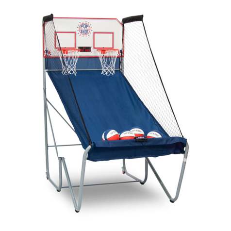
Pop-A-Shot Home User manual

Assembly Instructions - Home/ Promotional Game
Page 2 of 9

Assembly Instructions - Home/ Promotional Game
Page 3 of 9
TIE THE CABLES
WITH SOME
ELECTRICAL TIES
POSITION POWER
CABLE UPWARD
For Home Game

Assembly Instructions - Home/ Promotional Game
Page 4 of 9
Although the game may be assembled by one person, it is much easier with an assistant.
____________________________________________________________________________________________________________________________________
1The game is shipped in two boxes. The long narrow box contains:
1 ea Left and Right Hand Net assemblies
1 ea Left and Right Hand Front Support assembly (25”)
1 ea Left and Right Hand Rear Support assembly (55”)
2 Long PVC tubes (91”)
1 Fabric Ramp Assembly
The square, flat box contains:
1 Backboard assembly with Electronics
1 Basketball goal
1 Net / Scoring ring assembly
5 Horizontal connector tubes (26”)
4 “Legs” (6.125”)
1 Hardware package
3 Basketballs
Tools Required:
A medium sized Phillips (cross point) screwdriver
A 3/8” wrench (or nut-driver)
A 9/16” wrench (or nut-driver)
A rubber or wooden (best option) mallet is very helpful!
____________________________________________________________________________________________________________________________________
2After verifying that all parts have been received, begin assembly as follows:
Remove from the long narrow box the two front support assemblies, and the
two rear support assemblies. Remove from the square flat box 3 of the 5-26”
long horizontal connector tubes. Assemble the two back support assemblies
into a rectangle by inserting the connector tubes into the openings in the fittings.
Insert the third tube into the four-way fittings on the front support assembly
making it into a “U” shape.
THE CONNECTING TUBES MUST BE FULLY SEATED INTO THE
FITTINGS!
This may best be accomplished by use of a mallet. However, if no mallet
is available, the following procedure may be employed to insure that the
joints are fully seated.
Assemble the rectangles as shown. Hold the rectangle assembly such that
the pre-assembled tubes are parallel to the floor, and the connecting tubes
are in a vertical position. Sharply strike the entire assembly onto the floor
such that the fittings are driven onto the connection tubes. Repeat this
several times.
Finally, look into the open end of each fitting to insure that the end of each
connecting tube has been fully seated against it’s “stop” inside the fitting. The
end of the connecting tube must be aligned with the edge of the tube which
enters the fitting at a right angle. There must be no space between the end
of the tube and the “stop” molded onto the fitting.

Assembly Instructions - Home/ Promotional Game
Page 5 of 9
3Lean the larger of the two pieces (made in step 1) against a wall
with the “4 way” fittings resting on the floor, and the open end of the
fittings toward you. Insert the ends of the two 92” long tubes into
these fittings so that the tubes extend toward you, away from the wall.
Align the smaller “U” shape piece made in step 1 with the extended ends of
the long tubes. Push the tubes into the fittings, then brace the larger
rectangle against the wall and drive the tubes into the fittings by use to
drive these components together, but a block of wood should be used
between the mallet and the fittings to protect the finish of the fitting.
PLEASE INSURE THAT THESE TUBES ARE FULLY SEATED
INTO THE FITTINGS BEFORE PROCEEDING!
____________________________________________________________________________________________________________________________________
4Install the ball return ramp by inserting the steel pipe into the large
holes in the front and rear support assemblies. Note that the ramp
has a hinged portion at one end. This end must be oriental toward
the REAR support assembly, i.e., the LARGER of the two rectangles.
After the steel tubes are inserted into the larger holes, they must be
secured using the 2” screws, and lock-nuts which are included in the
hardware package. Finally, the hinged portion should be raised into
position such that the steel tubes may be attached to the plastic tube
by inserting the 3” screws through both tubes, and securing with the
remaining lock-nuts.
____________________________________________________________________________________________________________________________________
5The backboard should no be attached by “plugging in” the lower end
of the vertical tubes into the fittings at the top of the large rectangle.
These connections must be made secure by pounding the tubes into
the fittings as described above.
Install the rim onto the backboard using the 3 large carriage bolts and
matching locknuts. (A 9/16” wrench is required). Rim net and scoring
collar is preassembled to the rim.
Plug the scoring cable into the electronics module through the hole
located near the upper, left corner of the electronics module rear cover
(as viewed from the rear). Plug the wall-mount transformer into the
electronics module through the hole at the bottom of the electronics
module rear cover.

Assembly Instructions - Home/ Promotional Game
Page 6 of 9
6Remove the Left and Right hand net assemblies from the long narrow
box. Unroll the net and un-fold the short plastic tube such that it is at
a right angle to the long tube. (These pieces are connected together
by the netting material). The end of the short piece should be inserted
into the fitting on the long tube, and pounded together to insure a secure
connection. The entire assembly may then be installed by inserting the
lower end of the shorter tube into the fitting at the top of the front support
assembly, then placing the remaining fitting over the backboard tube.
NOTE THAT THE OPEN ENDS OF THE 3 WAY FITTINGS AT THE
FRONT OF THE GAME MUST FACE TOWARD THE INSIDE OF
THE GAME. Insert the remaining connecting tube into these fittings and
pound together until secure.
____________________________________________________________________________________________________________________________________
7At the conclusion of step 6 the nets should be hanging smoothly from the
upper tubes, with the wooden dowels at the bottom. These dowels are
used to secure the nets to the ramp and backboard.
The nets are attached to the rear surface of the backboard by hooking the
vertical dowels behind the “cup” hooks.
____________________________________________________________________________________________________________________________________
8There are four small slits in the ramp fabric on the underside of the slanted
portion of the ramp, near the top and bottom edges of the “pocket” which
encloses the short steel tubes. Insert the ends of each of the two diagonal
dowels into these slits (it may be necessary to remove the tape holding the
dowel to the net before inserting the dowel in slit. Tapes should be replaced
if possible). Pull the loose net around the plastic tube and hook around the
locknut at the top of the slanted ramp. (See Photo).

Assembly Instructions - Home/ Promotional Game
Page 7 of 9
9
Three loops of string, with attached hooks, are used to pull the dowels at the bottom of the nets toward each other, thereby
providing tension on the nets. Attach the string to the dowel on one of the nets by looping around the dowel and pulling the
hook through.
Place the hook around the dowel on the other net, pulling the dowel toward on another and providing tension the nets. The
loops are of three different lengths and should be used with the shortest toward the rear of the game, with the longer one used
closer to the front. Adjust the location of the string to provide the correct tension for the best net appearance. The string can
be shorten by placing another knot further up the end (with the existing knot).
____________________________________________________________________________________________________________________________________
10
The optional legs may be installed by lifting each corner of the game
and inserting the leg into the fitting as shown.
______________________________________________________________________________________________
Pop-A-Shot, Inc.
Office: (785) 827-6229 Toll Free (866) 929-6229
Fax (785) 827-6336
200 N. 3rd * P.O. Box 1073 *Salina, KS 67402-1073

Assembly Instructions - Home/ Promotional Game
Page 8 of 9
POP-A-SHOT, INC.
TERMS AND CONDITIONS
SALES OFFICE: Monday-Friday 8:00 am - 5:00 pm CST
PHONE: (866-929-6229) FAX (785-827-6336)
CREDIT:
Payment is due in advance of shipment. Pop-A-Shot accepts VISA, MasterCard, Discover or American Express.
Pop-A-Shot also accepts checks in advance of shipment. Quantity orders require 50% with firm purchase order
and 50% prior to delivery.
FREIGHT:
All products are shipped Federal Express or common carrier.
DAMAGE IN TRANSIT:
If merchandise is damaged in transit it is the customer’s responsibility to properly notate the damage on the freight
bill at the time of receipt in order to secure proper settlement from the carrier. Pop-A-Shot, Inc., is not responsible
for goods damaged in transit.
WARRANTY:
All electronic games carry a warranty for 90 days against defective workmanship and/or materials when used for
the purpose intended, under normal conditions. To obtain the warranty service the original purchaser must return
the product to designated customer service site.
RETURN POLICY:
Returns must follow prior authorization given by Pop-A-Shot, Inc. If an item must be returned, contact
Pop-A-Shot, Inc. to receive a return authorization number. This RA# must be clearly marked on ALL shipping
labels. All returns must be shipped prepaid. Collect shipments will not be accepted. Upon receipt of returned
goods, Pop-A-Shot, Inc. reserves the right to inspect and issue credit for items determined to be covered by
warranty. A 35% restocking charge may be assessed on all returned goods. Pop-A-Shot, Inc. reserves the right to
charge 50% restocking fees on any customized games. Pop-A-Shot, Inc. will not accept used games.

Assembly Instructions - Home/ Promotional Game
Page 9 of 9
MANUFACTURER’S 90 DAY LIMITED WARRANTY
This Pop-A-Shot product carries a warranty for 90 days against defective workmanship and/or materials when
used for the purpose intended, under normal conditions, and provided it receives proper care. This warranty
extends only to the original purchaser of the product. To obtain warranty service the original purchaser must
return the product, together with proof of purchase, to Pop-A-Shot, Inc. 200 N. 3rd Street, Salina, Kansas 67401.
All warranty items will be returned to original purchaser freight collect. All non-warranty items will be returned
to original purchaser, Net C.O.D., freight collect. The original purchaser must present the sales receipt or other
document, which establishes proof of purchase and the date of purchase. Pop-A-Shot, Inc. will inspect the
returned product to determine whether repair, replacement or credit is in order. THE RETURN OF THE
OWNER REGISTRATION CARD IS NOT A CONDITION OF WARRANTY COVERAGE. However,
please detach and return the Owner Registration Card so that Pop-A-Shot, Inc. can contact you should a question
of safety arise which could affect you.
The warranty provided herein is in lieu of all other expresses warranties. Any implies warranties, including any
implied warranties of merchantability or fitness for a particular purpose, are limited in duration to the first 90 days
from the date of purchase. All other obligations or liabilities, including liability for consequential damages, are
hereby excluded.
Some states do not allow limitations on how long an implied warranty lasts or do not allow the exclusion or
limitation of incidental or consequential damages, so the above limitations or exclusion may not apply to you.
This warranty gives you specific legal rights, and you may also have other rights, which vary, from state to state.
POP-A-SHOT, INC.
Office (785) 827-6229 Fax (785) 827-6336
200 N. 3rd, PO Box 1073 Salina, Kansas 67402-1073
CLIP AND FORWARD TO ABOVE ADDRESS
OWNER REGISTRATION CARD
-----------------------------------------------------------------------------------------------------------------------------
Please Print
Name:________________________________________________________________________
Address: ______________________________________________________________________
City and State:__________________________________________________________________
Phone Contact Number(s): ________________________________________________________
Game Model:___________________________ Date of Purchase:_________________________
This manual suits for next models
1
Table of contents
Other Pop-A-Shot Game manuals
Popular Game manuals by other brands

Barbie
Barbie Barbie BW68 instruction manual

Tiger Electronics
Tiger Electronics Baseball Electronic LCD Game 7-741 instruction manual

Vonset
Vonset TALKING CHESS MASTER 3 quick start guide

Jennison Entertainment Technologies
Jennison Entertainment Technologies Kahuna's Big Wave Service manual

Hasbro
Hasbro Poppin' Bedbugs Pinball 06102 instruction manual

Disney
Disney Disney Princess owner's manual