944 Table
of
contents volume
1-A
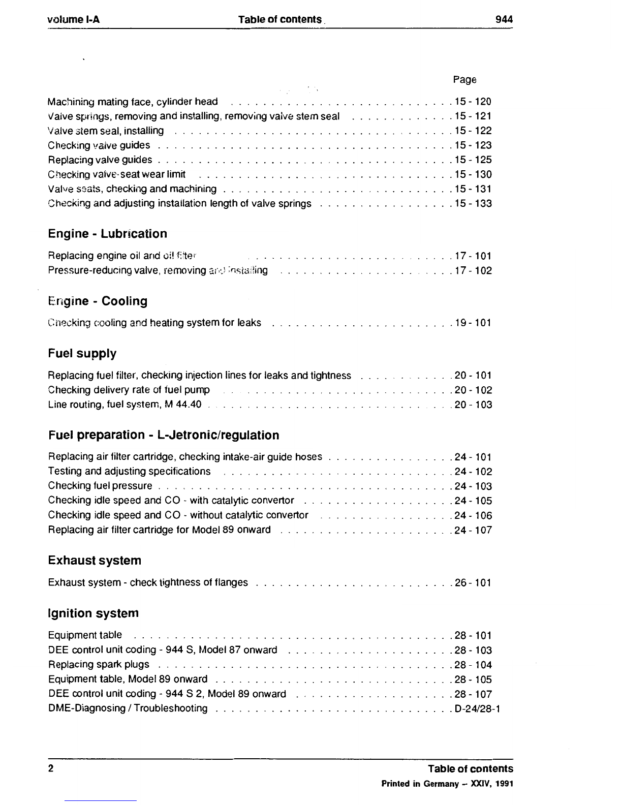
Page
General
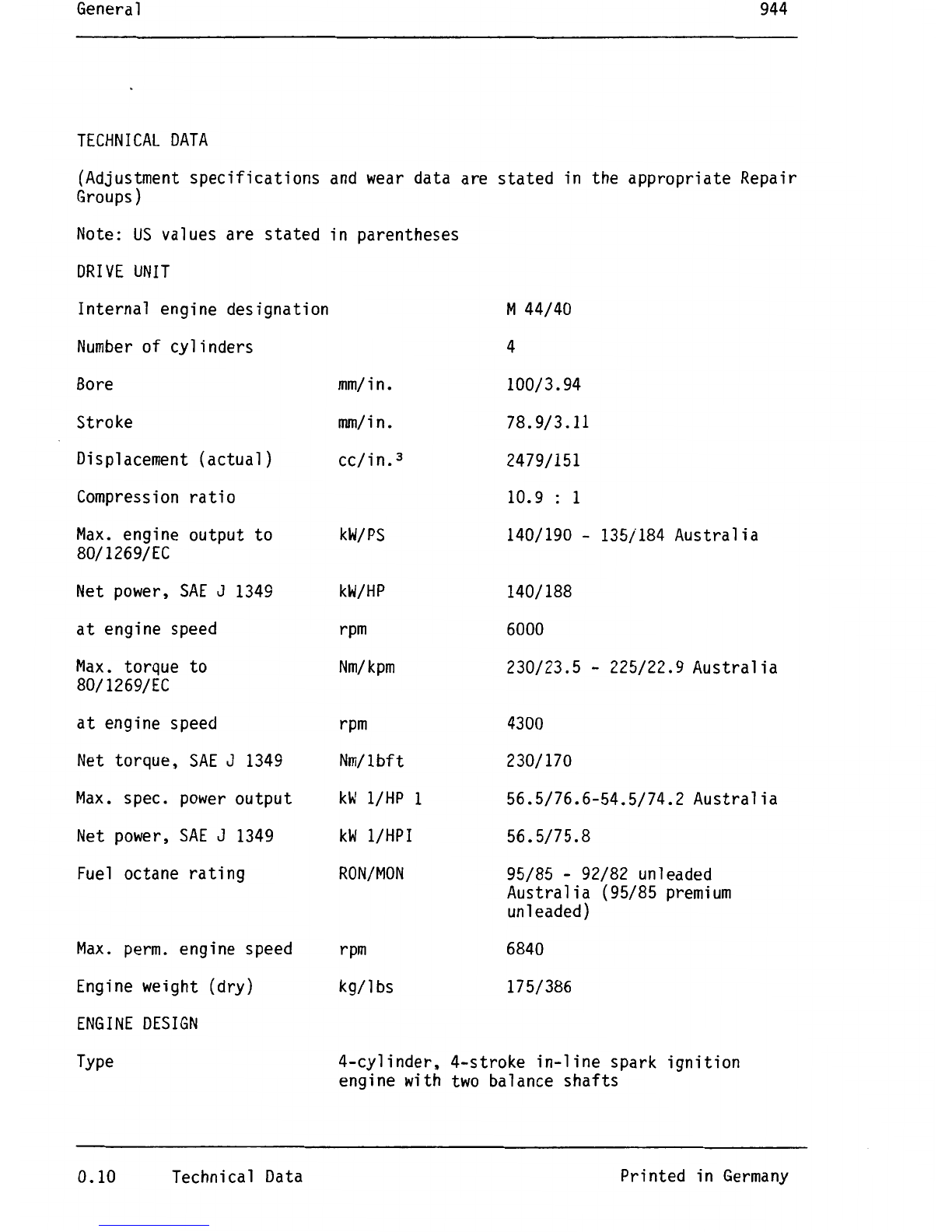
Technicaldata
...........................
0.9
Maintenance, Self-diagnosis
Fault diagnosis, DEE control unit
Connecting into the vehicle -944 S .
Starting fault diagnosis . . . . . . . .
Functional test -actuator and input signal .
List of test codes . . . . . . . . .
System adaptation
Knock detection .
Troubleshooting . .
List of fault codes .
Clearing fault memory
Operating conditions for start of diagnosis
Operating instructions for System Tester 9288
Engine, Crankcase
Tightening torques for engine (16-valve)
Tolerances and wear limits
...
Engine, removing and installing
....
Engine, Crankshaft drive, Pistons
Notes on assembly for pistons, from Model 87 onward
Checking pistons and cylinder bore . . .
Pistons from Model
89
onward . . . . . .
Installing cover for oil-centrifuge partition
Engine, Cylinder head, Valve drive
Camshaft setting, checking and adjusting . . . . . . . . . . . .
Camshaft setting, checking and adjusting for Model 89 onward
Applying the TDC mark on the camshaft sprocket . . .
Camshafts and cylinder head, removing and installing .
Cylinder head, installing and tightening
Camshafts,installing
Camshaftseal, installing . . . . . . . .
Camshaftspecifications . . . . . . . . .
Chain tensioner, removing and installing
Cylinder head, disassembling and assembling
Valve springs, removing and installing with Sauertool
Table
of
contents
Printed
in
Germany-
XXIV,
1991
03-
03-
3
03-
5
03-
7
03-
13
03-
15
03-
17
0:1
-19
03-29
03-31
03-32
03-33
10-0101
10-0102
10-
101
13-101
13-
102
13-
103
13-
105
15-
101
15-
104 a
15-
104 b
15-
105
15-110
15-111
15-112a
15-112b
15-113
15-115
15-118
1