Posital Fraba CANopen User manual

POSITAL GmbH
Carlswerkstraße 13c, D-51063 Köln, Telefon +49(0)221-96213-0, Telefax +49(0)221-96213-20
Main Features
-Compact and heavy-duty industrial design
-Interface: CANopen (DS406)
CANopen Lift (DSP417)
-Housing: 36 mm
-Solid shaft: 6 or 10mm
-Blind hollow shaft: 6mm
-Max. 4096 steps per revolution (12 Bit)
-Max. 32768 revolutions (15 Bit)
-Code: Binary
-Velocity Output
-LSS services
Mechanical Structure
-Aluminium flange and housing
-Nickel-plated steel housing
Stainless steel shaft
Precision ball bearings
Programmable Parameters
-Direction of rotation (complement)
-Resolution per revolution
-Total resolution
-Preset value
-Two limit switches and eight cams
-Baud rate and CAN-identifier
-Transmission mode: Polled mode, cyclic
mode, sync mode
Electrical Features
-Programmable Termination Resistor
-Polarity inversion protection
-Over-voltage-peak protection
-Galvanic Isolation
ABSOLUTE ROTARY ENCODER WITH CANOPEN INTERFACE
USER MANUAL

Version 02/09 UME-MCD-CA 2
ABSOLUTE ROTARY ENCODER
CANOPEN
Table of Contents
Main Features........................................................1
Mechanical Structure.............................................1
Programmable Parameters....................................1
Electrical Features.................................................1
Table of Contents.................................................2
General Security Advise......................................4
About this Manual................................................4
1. Introduction......................................................5
1.1 General CANopen Information.........................5
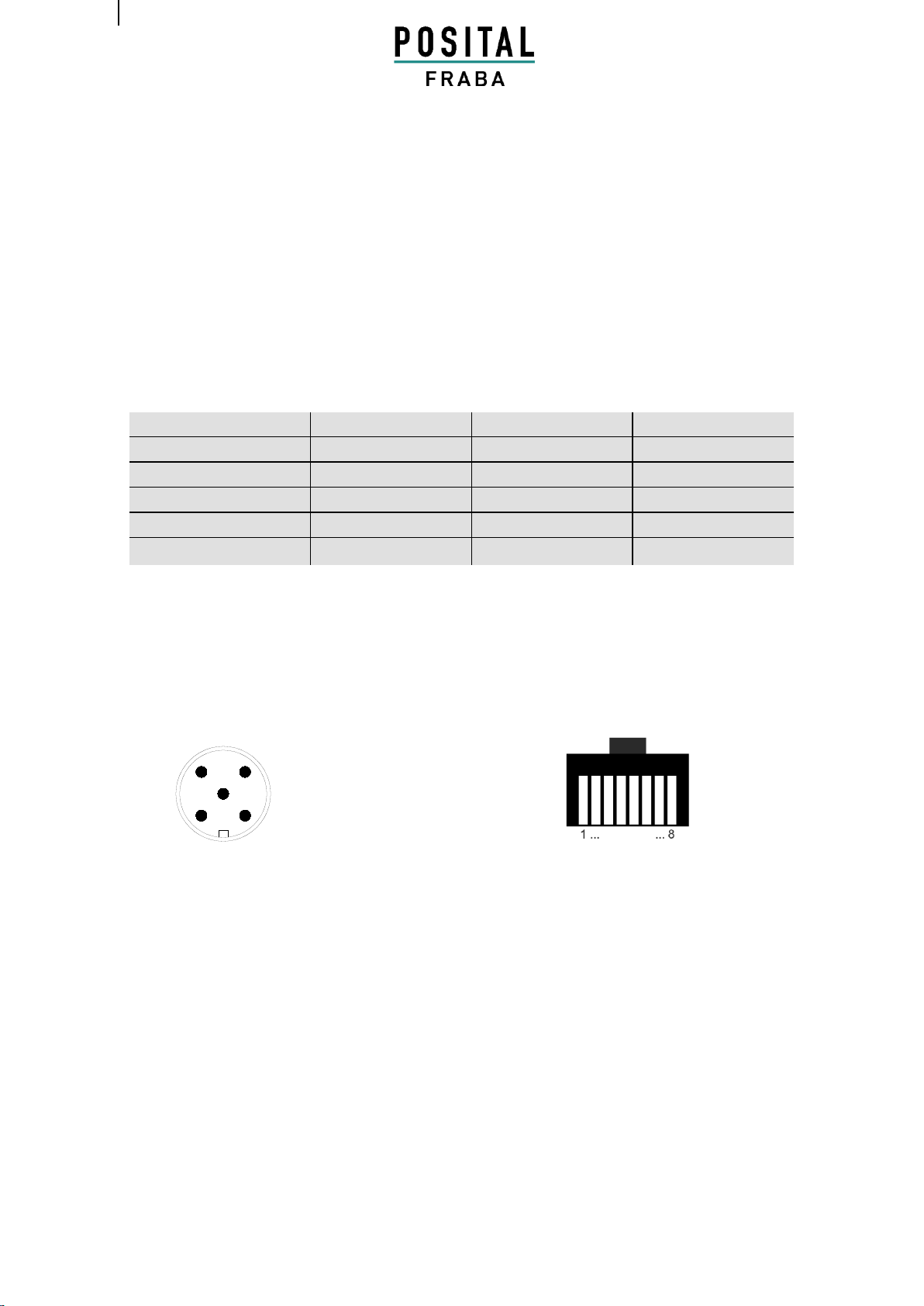
2. Installation........................................................7
2.1 Electrical Connection.......................................7
3. Technical Data..................................................9
Electrical Data........................................................9
Sensor data............................................................9
Tab. 3 Sensor data....................................................9
Flange..................................................................10
Synchro (S)..........................................................10
Blind hollow shaft (B)...........................................10
Clamp (C) ............................................................10
Minimum Mechanical Lifetime..............................10
Cable ...................................................................10
4. Configuration .................................................11
4.1 Operating Modes ...........................................11
4.1.1 General.......................................................11
4.1.2 Mode: Preoperational..................................11
4.1.3 Mode: Start - Operational............................11
4.1.4 Mode: Stopped............................................11
4.1.2 Reinitialization of the Encoder.....................12
4.2 Normal Operating...........................................12
4.3 Storing Parameter..........................................13
4.3.1 List of storable Parameter...........................13
4.3.1 Storing Procedure.......................................13
4.4 Restoring Parameters....................................14
4.5 Usage of Layer Setting Services (LSS)..........14
5. Programmable Parameters ...........................16
5.1 Programming example: Preset Value ............17
5.1.1 Set Encoder Preset Value...........................17
5.2 Communication Profile DS301 specific
objects from 1000h - 1FFFh.................................18
5.3 Manufacturer specific objects 2000h –
5FFFh..................................................................19
5.4 Application specific objects 6000h –67FEh .. 19
5.5 Object Descriptions ....................................... 20
Object 1000h: Device Type ................................. 20
Object 1001h: Error Register............................... 21
Object 1003h: Pre-Defined Error Field ................ 21
Object 1005h: COB-ID Sync................................ 22
Object 1008h: Manufacturer Device Name.......... 22
Object 1009h: Manufacturer Hardware Version... 22
Object 100Ah: Manufacturer Software Version.... 22
Object 100Ch: Guard Time.................................. 23
Object 100Dh: Life Time Factor........................... 23
Object 1010h: Store Parameters......................... 23
Object 1011h: Restore Parameters..................... 24
Object 1012h: COB-ID Time Stamp Object......... 24
Object 1013h: High Resolution Time Stamp........ 24
Object 1014h: COB-ID Emergency Object .......... 25
Object 1016h: Consumer Heartbeat Time........... 25
Object 1017h: Producer Heartbeat Time............. 25
Object 1018h: Identity Object .............................. 26
Object 1020h: Verify configuration....................... 26
Object 1029h: Error behaviour............................. 26
Object 1800h: 1st Transmit PDO Communication
Parameter............................................................ 27
Object 1801h: 2nd Transmit PDO Communication
Parameter............................................................ 27
Event Timer......................................................... 28
Object 1A00h: 1st Transmit PDO Mapping
Parameter............................................................ 28
Object 1A01h: 2nd Transmit PDO Mapping
Parameter............................................................ 29
Object 1F50h: Download Program Area.............. 29
Object 1F51h: Program Control........................... 29
Object 2000h: Position Value .............................. 30
Object 2100h: Operating Parameters.................. 30
Object 2101h: Resolution per Revolution ............ 31
Object 2102h: Total Resolution ........................... 31
Object 2103h: Preset Value................................. 32
Object 2104h: Limit Switch, min. ......................... 32
Object 2105h: Limit Switch, max. ........................ 33
Object 2160h: Customer storage......................... 33
Object 2200h: Cyclic Timer PDO......................... 34

Version 02/09 UME-MCD-CA 3
ABSOLUTE ROTARY ENCODER
CANOPEN
Object 2300h: Save Parameter with Reset..........34
Object 3000h: Node Number ...............................34
Object 3001h: Baudrate.......................................35
Object 3010h: Speed Control...............................35
Object 3011h: Speed Value.................................36
Object 3020h: Acceleration Control .....................36
Object 3021h: Acceleration Value........................36
Object 4000h: Bootloader Control........................36
Object 6000h: Operating parameters...................37
Object 6001h: Measuring units per revolution......38
Object 6002h: Total measuring range in
measuring units....................................................38
Object 6003h: Preset value..................................38
Object 6004h: Position value...............................38
Object 6030h: Speed Value.................................39
Object 6040h: Acceleration Value........................39
Object 6200h: Cyclic timer...................................39
Object 6300h: Cam state register ........................40
Object 6301h: Cam enable register .....................40
Object 6302h: Cam polarity register.....................40
Object 6400h: Area state register ........................43
Object 6401h: Work area low limit .......................44
Object 6402h: Work area high limit...................... 44
Object 6500h: Operating status........................... 44
Object 6501h: Single-turn resolution ................... 45
Object 6502h: Number of distinguishable
revolutions........................................................... 45
Object 6503h: Alarms.......................................... 45
Object 6504h: Supported alarms......................... 46
Object 6505h: Warnings...................................... 46
Object 6506h: Supported warnings ..................... 47
Object 6507h: Profile and software version......... 47
Object 6508h: Operating time.............................. 47
Object 6509h: Offset value.................................. 48
Object 650Ah: Module identification .................... 48
Object 650Bh: Serial number............................... 48
6. Diagnosis ....................................................... 49
6.2 Troubleshooting............................................. 49
7. Mechanical Drawings.................................... 50
Appendix A: Order Codes................................. 53
Appendix B: History.......................................... 54
Appendix C: Glossary....................................... 55
Appendix D: List of tables ................................ 58
Appendix E: Document history........................ 58

Version 02/09 UME-MCD-CA 4
ABSOLUTE ROTARY ENCODER
CANOPEN
General Security Advise
Important Information
Read these instructions carefully, and look at the
equipment to become familiar with the device
before trying to install, operate, or maintain it.
The following special messages may appear
throughout this documentation or on the
equipment to warn of potential hazards or to call
attention to information that clarifies or simplifies
a procedure.
The addition of this symbol to a
Danger or Warning safety label
indicates that an electrical hazard
exists, which will result in personal injury if the
instructions are not followed.
This is the safety alert symbol. It is
used to alert you to potential
personal injury hazards. Obey all
safety messages that follow this symbol to avoid
possible injury or death.
Please Note
Electrical equipment should be serviced only by
qualified personnel. No responsibility is assumed
by POSITAL for any consequences arising out of
the use of this material. This document is not
intended as an instruction manual for untrained
people.
About this Manual
Background
This user manual describes how to install and
configure an MCD absolute rotary encoder with
CANopen interface.
Relate Note
Version date: 08. October 2010
Version number: 10/10
Reference number: UKE20101008
Imprint
POSITAL GmbH
Carlswerkstrasse 13c
D-51063 Köln
Telefon +49 (0) 221 96213-0
Telefax +49 (0) 221 96213-20
Internet http://www.posital.eu
Copyright
The company POSITAL GmbH claims copyright
on this documentation. It is not allowed to
modify, to extend, to hand over to a third party
and to copy this documentation without written
approval by the company POSITAL GmbH. Nor
is any liability assumed for damages resulting
from the use of the information contained herein.
Further, this publication and features described
herein are subject to change without notice.
User Annotation
The POSITAL GmbH welcomes all readers to
send us feedback and commands about this
document. You can reach us by e-mail at

Version 02/09 UME-MCD-CA 5
ABSOLUTE ROTARY ENCODER
CANOPEN
1. Introduction
This manual explains how to install and
configure the MAGNETOCODE absolute rotary
encoder with CANopen interface applicable for
both military and industrial applications with
CANopen interface. The products are fully
compliant with standard DS406.
Measuring System
Magnetic rotary encoder determine
positions using the Hall effect sensor
technology developed for the automotive
mass market. A permanent magnet fixed to
the shaft generates a magnetic field that is
sampled by the Hall sensor, which
translates the measured value into a unique
absolute position value.
To register revolutions even when no
voltage is applied, energy from the turning
of the shaft must suffice for proper
operation. An innovative, patented
technology makes this feasible even at low
rotational speeds and through long
standstill periods –a Wiegand wire ensures
that the magnetic field can only follow the
turning of the shaft in discrete steps. A coil
wound on the Wiegand wire receives only
brief, strong voltage spikes, which prompt
the reliable recognition of each revolution.
Typical Applications:
• Packing Machines
• Mobile Machines
• Wind Mills
• Medical Equipment
1.1 General CANopen Information
The CANopen system is used in industrial
applications. It is a multiple access system
(maximum: 127 participants), which means that
all devices can access the bus. In simple terms,
each device checks whether the bus is free, and
if it is the device is able to send messages. If two
devices try to access the bus at the same time,
the device with the higher priority level (lowest
ID number) has permission to send its message.
Devices with the lowest priority level must delay
their data transfer and wait before retrying to
send their message. Data communication is
carried out via messages. These messages
consist of 1 COB-ID followed by a maximum of 8
bytes of data. The COB-ID, which determines
the priority of the message, consists of a
function code and a node number. The node
number corresponds to the network address of
the device. It is unique on a bus. The function
code varies according to the type of message
being sent:
Management messages (LMT, NMT)
Messaging and service (SDOs)
Data exchange (PDOs)
Layer Setting Services (LSS)
Predefined messages (synchronization,
emergency messages)

Version 02/09 UME-MCD-CA 6
ABSOLUTE ROTARY ENCODER
CANOPEN
The absolute rotary encoder supports the
following operating modes:
Polled mode: The position value is only
sent on request.
Cyclic mode: The position value is sent
cyclically (regular, adjustable interval)
on the bus.
SYNC mode: The position value is sent
after a synchronization message
(SYNC) is received. The position value
is sent every n SYNCs (n ≥ 1).
Other functions (offset values, resolution, etc)
can be configured. The absolute rotary encoder
corresponds to the class 2 encoder profile (DS
406 in which the characteristics of encoder with
CANopen interface are defined). The node
number and speed in bauds are determined by
their corresponding object dictionary entries.
The transmission speed can range from
20kBaud up to 1Mbaud (30m cable for a
maximum speed of 1Mbaud, 1000m cable for a
maximum speed of 20 kbaud). Various software
tools for configuration and parameter-setting are
available from different suppliers. It is easy to
align and program the rotary encoders using the
EDS (electronic data sheet) configuration file
provided.
Further information is available at:
CAN in Automation (CiA) International Users
and Manufacturers Group e.V.
Kontumazgarten 3
DE-90429 Nurenberg
(*) Reference: CAN Application Layer for
Industrial Applications
CiA Draft Standard 201 ... 207, Version
1.1
CAL-based Communication Profile for
Industrial Systems
CiA Draft Standard 301
CiA Draft Standard 305 Layer Setting
Services
CiA Draft Standard 406 Device Profile
for Encoders
Note: All datasheets and manuals can be
downloaded for free from our website
www.posital.eu
We do not assume responsibility for
technical inaccuracies or omissions.
Specifications are subject to change without
notice.

Version 02/09 UME-MCD-CA 7
ABSOLUTE ROTARY ENCODER
CANOPEN
2. Installation
2.1 Electrical Connection
5 pin male M12 connector RJ45 Connector
Tab.1 Signal Assignment Connector / Cable
1
4
2
3
5
Function
Wire end
Connector Pin RJ45
Connector Pin M12
Can High
white
1
4
Can Low
brown
2
5
Can-GND
green
3
1
GND
yellow
4
3
+ Ub= 10-30 V
red
8
2

Version 02/09 UME-MCD-CA 8
ABSOLUTE ROTARY ENCODER
CANOPEN
Setting Node Number via SDO Objects
The node number has to be adjusted via SDO
objects. The default node number is 32. To set
the node number, object 3000h has to be
written. For further information regard
chapter 5.5 Object Dictionary.
Setting Baud Rate via SDO Objects
The baud rate has to be adjusted via SDO
objects. The default baud rate is 125 kBaud. To
set baud rate object 3001h has to be written. For
further information please regard chapter 5.5
Object Dictionary.
Setting Node Number via LSS
The node number can also be adjusted via
Layer Setting Services (LSS). For further
information regard chapter 4.5
Setting Baud Rate via LSS
The baud rate can also be adjusted via Layer
Setting Services (LSS). The default baud rate is
125 kBaud. For further information regard
chapter 4.5.
Bus Termination
If the encoder is the last device in the bus you
can use the internal termination resistor which
can be enabled with an SDO object..

Version 02/09 UME-MCD-CA 9
ABSOLUTE ROTARY ENCODER
CANOPEN
3. Technical Data
In the following section you will find general technical data about MCD absolute rotary encoders with
CANopen interface.
Electrical Data
Interface
Transceiver according ISO 11898,
galvanically isolated by opto-couplers
Transmission rate
max. 1 MBaud
Device addressing
Adjustable by SDO telegrams or Layer Setting Services
Supply voltage
10 –30* V DC (absolute limits)
Current consumption
max. 100 mA with 10 V DC, max. 50 mA with 24 V DC
Power consumption
max. 1,2 Watts
EMC
Emitted interference: EN 61000-6-4
Noise immunity: EN 61000-6-2
Electrical lifetime
> 105 h
Tab. 2 Electrical Data
*Absolute rotary encoders should be connected only to subsequent electronics whose power supplies comply with EN
50178 (protective low voltage)
Sensor data
Singleturn technology
magnetic 2 axis Hall sensor
Singleturn resolution
up to 4096 steps / revolution (12 Bit)
Singleturn accuracy
+/-0,35°
Internal cycle time
< 1 ms
Multiturn technology
self supplied magnetic pulse counter
Multiturn resolution
Can measure up to 200 Billion revolutions
Tab. 3 Sensor data
Environmental Conditions
Operating temperature
- 30 ... + 85 °C (M12 connector version
- 30 ... + 70 °C (Cable exit version) *
Storage temperature
- 30 ... + 85 °C (M12 connector version
- 30 ... + 70 °C (Cable exit version) *
Humidity
98 % (without liquid state)
Protection Class (EN 60529)
Casing side: IP54 (Cable exit version)
IP65 (M12 Connector version)
Shaft side: IP65
Tab.4 Environmental Conditions

Version 02/09 UME-MCD-CA 10
ABSOLUTE ROTARY ENCODER
CANOPEN
Mechanical Data
Housing
Nickel-plated iron housing
Flange
Aluminium
Shaft
Stainless steel
Lifetime
Dependent on shaft version and shaft loading –refer to table
Max. shaft loading
Axial 40 N, radial 110 N
Inertia of rotor
30 gcm2
Friction torque
3 Ncm
RPM (continuous operation)
max. 12.000 RPM
Shock (EN 60068-2-27)
100 g (half sine, 6 ms)
Permanent shock (EN 60028-2-29)
10 g (half sine, 16 ms)
Vibration (EN 60068-2-6)
10 g (10 Hz ... 1,000 Hz)
Weight (standard version)
150 g, including cable
Flange
Synchro (S)
Blind hollow shaft (B)
Clamp (C)
Shaft diameter
6 mm
6 mm
10 mm
Shaft length
11,5 mm
-
20 mm-
Hollow shaft depth min. / max.
-
8 mm / 18 mm
-
Tab. 5 Mechanical data
Minimum Mechanical Lifetime
Flange
Lifetime in 108revolutions with Fa/ Fr
40 N / 60 N
40 N / 80 N
40 N / 110 N
S06 (Synchro flange 6 x 11.5)
216
91
35
Tab. 6 Minimum Mechanical Lifetime
Cable
Operating temperature cable
flexing -5°C bis +70°C
static -30°C bis +70°C
Minimum bend radius
flexing 10x cable diameter
static 5x cable diameter
Cable
aprox 6 mm / type : LIYCY 4x2x0.14
Tab.7 Cable properties

Version 02/09 UME-MCD-CA 11
ABSOLUTE ROTARY ENCODER
CANOPEN
4. Configuration
The purpose of this chapter is to describe the configuration parameters of the absolute rotary encoder with
CANopen interface.
4.1 Operating Modes
4.1.1 General
The encoder accesses the CAN network after
powerup in pre-operational mode:
BootUp Message: 700 hex + Node Number
It is recommended that the parameters can be
changed by the user when the encoder is in
preoperational mode. Pre-operational mode
entails reduced activity on the network, which
simplifies the checking of the accuracy of the
sent/received SDOs. It is not possible to send or
receive PDOs in pre-operational mode.
4.1.2 Mode: Preoperational
To set a node to pre-operational mode, the master must send the following message:
Identifier
Byte 0
Byte 1
Description
0 h
80 h
00
NMT-PreOp, all nodes
0 h
80 h
NN
NMT-PreOp, NN
NN: node number
It is possible to set all nodes (Index 0) or a single node (Index NN) to pre-operational mode.
4.1.3 Mode: Start - Operational
To put one or all nodes in the operational state, the master have to send the following message:
Identifier
Byte 0
Byte 1
Description
0 h
01 h
00
NMT-Start, all nodes
0 h
01 h
NN
NMT-Start, NN
NN: node number
It is possible to set all nodes (Index 0) or a single node (Index NN) to operational mode.
4.1.4 Mode: Stopped
To put one or all nodes in the stopped state, the master have to send the following message:
Identifier
Byte 0
Byte 1
Description
0 h
02 h
00
NMT-Stop, all nodes
0 h
02 h
NN
NMT-Stop, NN

Version 02/09 UME-MCD-CA 12
ABSOLUTE ROTARY ENCODER
CANOPEN
NN: node number
It is possible to set all nodes (Index 0) or a single node (Index NN) to stop mode.
4.1.2 Reinitialization of the Encoder
If a node is not operating correctly, it is advisable to carry out a reinitialization:
NN
Command
Index
Description
0 h
82 h
00
Reset Communication
0 h
81 h
NN
Reset Node
NN: node number
It is possible to set all nodes (Index 0) or a single node (Index NN) in reset mode.
After reinitialization, the encoder accesses the bus in pre-operational mode.
4.2 Normal Operating
Polled Mode
By a remote-transmission-request telegram the connected host calls for the
current process value. The encoder reads the current position value,
calculates eventually set-parameters and sends back the obtained process
value by the same identifier.
Cyclic Mode
The encoder transmits cyclically - without being called by the host - the
current process value. The cycle time can be programmed in milliseconds
for values between 1 ms and 65536 ms.
Sync Mode
After receiving a sync telegram by the host, the encoder answers with the
current process value. If more than one node number (encoder) shall
answer after receiving a sync telegram, the answer telegrams of the nodes
will be received by the host in order of their node numbers. The
programming of an offset-time is not necessary. If a node should not answer
after each sync telegram on the CAN network, the parameter sync counter
can be programmed to skip a certain number of sync telegrams before
answering again.
Tab. 8 CAN Transmission Mode Description

Version 02/09 UME-MCD-CA 13
ABSOLUTE ROTARY ENCODER
CANOPEN
4.3 Storing Parameter
4.3.1 List of storable Parameter
Object Index
Object Description
1005h
COB-ID Sync
100Ch
Guard Time
100Dh
Life Time Factor
1016h
Consumer Heartbeat Time
1017h
Producer Heartbeat Time
1020h
Verify configuration
1800h
Communication parameter PDO 1
1801h
Communication parameter PDO 2
1A00h
Transmit PDO1 Mapping Parameter
1A01h
Transmit PDO2 Mapping Parameter
2100h
Operating Parameters
2101h
Resolution per Revolution
2102h
Total Resolution
2103h
Preset Value
2104h
Limit Switch, min.
2105h
Limit Switch, max.
2160h
Customer Storage
2200h
Cyclic Timer
3000h
Node Number
3001h
Baud rate
3002h
Termination Resistor
6000h
Operating Parameter
6001h
Steps per Revolution
6002h
Total Resolution
6003h
Preset Value
6200h
Cyclic Timer
Tab. 9 List of Storable Parameters
4.3.1 Storing Procedure

Version 02/09 UME-MCD-CA 14
ABSOLUTE ROTARY ENCODER
CANOPEN
The parameter settings can be stored in a non-
volatile E2PROM. The parameter settings are
stored in RAM when being programmed. When
all the parameters are set and proved, they can
be transferred in one burn cycle to the E2PROM
by the parameter memory transfer. The
stored parameters are copied after a RESET
(Power on, NMT-Reset) from the E2PROM to
the RAM (volatile memory).
Storing without Reset
By using the object 1010h from the
communication profile related object dictionary
you can store the parameters into the non-
volatile memory without a reset.
Storing with Reset
By using the object 2300h from the manufacturer
specific object dictionary you can store the
parameters into the non-volatile memory. After
storing the parameters a reset of the device is
performed.
4.4 Restoring Parameters
The default parameters can be restored by using
the object 1011h from communication profile
related object dictionary. The already in the non-
volatile memory programmed parameters are
not overwritten. Only after a new store command
the default parameters are stored in the non-
volatile memory. To restore the default
parameter the following telegram is used. The
restored parameters are equal for every type of
CANopen encoder and might not fit with the
status after delivery. Please check the restored
parameters before you store them to the non-
volatile memory.
4.5 Usage of Layer Setting Services (LSS)
To configure the encoder via LSS the encoder
will be the LSS slave device and the control has
to support LSS master device functionality.
The LSS master device requests services, that
are performed by the LSS slave devices
(encoder). The LSS master device requests the
LSS address (vendor-id, product-code, revision-
number, serial-number) from the LSS slave
device. After receiving this information the
control can unequivocally identify the encoder
and the node number and baud rate can be set.

Version 02/09 UME-MCD-CA 15
ABSOLUTE ROTARY ENCODER
CANOPEN

Version 02/09 UME-MCD-CA 16
ABSOLUTE ROTARY ENCODER
CANOPEN
5. Programmable Parameters
Objects are based on the CiA 406 DS V3.2: CANopen profile for encoders (www.can-cia.org)
Command
Function
Telegram
Description
22h
Domain Download
Request
Parameter to Encoderr
23h, 27h, 2Bh, 2Fh (*)
Domain Download
Request
Parameter to Encoder (Bytes
indicated)
60h
Domain Download
Confirmation
Parameter received
40h
Domain Upload
Request
Parameter request
43h, 47h, 4Bh, 4Fh (*)
Domain Upload
Reply
Parameter to Master (Bytes
indicated)
80 h
Warning
Reply
Transmission error
Tab. 10 General Command Byte Description
(*)The value of the command byte depends on the data length of the called parameter:
Command
Data length
Data type
Command
Data length
Data type
43h
4 Byte
Unsigned 32
23h
4 Byte
Unsigned 32
47h
3 Byte
Unsigned 24
27h
3 Byte
Unsigned 24
4Bh
2 Byte
Unsigned 16
2Bh
2 Byte
Unsigned 16
4Fh
1 Byte
Unsigned 8
2Fh
1 Byte
Unsigned 8
Tab. 11 Detailed Command Byte Description
Object Dictionary
The data transmission according to CAL is realized
exclusively by object oriented data messages. The
objects are classified in groups by an index record.
Each index entry can be subdivided by sub-indices.
The overall layout of the standard object dictionary is
shown beside:
Index (hex)
Object
0000
not used
0001-001F
Static Data Types
0020-003F
Complex Data Types
0040-005F
Manufacturer Specific Data Types
0060-0FFF
Reserved for further use
1000-1FFF
Communication Profile Area
2000-5FFF
Manufacturer Specific Profile Area
6000-9FFF
Standardized Device Profile Area
A000-FFFF
Reserved for further use
Tab. 12 Overview Object Dictionary

Version 02/09 UME-MCD-CA 17
ABSOLUTE ROTARY ENCODER
CANOPEN
5.1 Programming example: Preset Value
If a CANopen device is connected and configured with the right baudrate and also configured to a unused
node number, it will start up into the pre-operational mode and send a bootup massage to the master.
5.1.1 Set Encoder Preset Value
Master to Encoder with Node Number 1
Setting Preset Value (Value 1000)
Identifier
DLC
Command
Index
Subindex
Service/Process data
NN 1
Download
6003h
Byte 4
Byte 5
Byte 6
Byte 7
601
8
22
03
60
00
00
10
00
00
Answer of the Encoder
Identifier
DLC
Command
Index
Subindex
Service/Process data
NN 1
Download
6003h
Byte 4
Byte 5
Byte 6
Byte 7
581
8
43
03
60
00
00
00
00
00
Read Preset Value from the Encoder
Identifier
DLC
Command
Index
Subindex
Service/Process data
NN 1
Download
6003h
Byte 4
Byte 5
Byte 6
Byte 7
601
8
40
03
60
00
00
00
00
00
Answer of the Encoder
Identifier
DLC
Command
Index
Subindex
Service/Process data
NN 1
Download
6003h
Byte 4
Byte 5
Byte 6
Byte 7
581
8
43
03
60
00
00
10
00
00
Save Preset Values
Identifier
DLC
Command
Index
Subindex
Service/Process data
NN 1
Download
1010h
Byte 4
Byte 5
Byte 6
Byte 7
601
8
22
10
10
01
73
61
76
65

Version 02/09 UME-MCD-CA 18
ABSOLUTE ROTARY ENCODER
CANOPEN
5.2 Communication Profile DS301 specific objects from 1000h - 1FFFh
In this manual we refer to the communication profile DS301 V4.02
Object
Description
Page
Hand-
Book
Page
DS301
Page
DS406
1000h
Device type
22
86
8
1001h
Error register
22
87
8
1003h
Pre-defined error field
22
88
1005h
COB-ID SYNC-message
23
89
1006h
ComCyclePeriode
23
90
1008h
Device name
24
91
1009h
Hardware version
24
91
100Ah
Software version
24
91
100Ch
Guard Time
24
92
100Dh
Life Time Factor
24
92
1010h
Store parameters
25
92
1011h
Restore default parameters
25
94
1012h
COB-ID Time Stamp
26
97
1013h
High Resolution Time Stamp
26
98
1014h
COB-ID Emergency
26
98
1016h
Consumer Heartbeat Time
26
100
1017h
Producer Heartbeat Time
27
101
1018h
Identity Object
27
101
1020h
Verify Configuration
117
1029h
Error Behaviour
133
9
1800h
Communication parameter PDO 1
28
111
9
1801h
Communication parameter PDO 2
28
111
11
1A00h
Transmit PDO1 Mapping Parameter
30
112
11
1A01h
Transmit PDO2 Mapping Parameter
30
112
12
1F50h
Download Program Area
1F51h
Program Control
Tab. 13 Object Dictionary 1000h-1FFFh

Version 02/09 UME-MCD-CA 19
ABSOLUTE ROTARY ENCODER
CANOPEN
5.3 Manufacturer specific objects 2000h –5FFFh
Object
Description
Page
Hand-Book
2000h
Position Value
31
2100h
Operating Parameters
31
2101h
Resolution per Revolution
31
2102h
Total Resolution
33
2103h
Preset Value
34
2104h
Limit Switch, min.
34
2105h
Limit Switch, max.
33
2160h
Customer Storage
35
2200h
Cyclic Timer
35
2300h
Save Parameter with reset
35
3000h
Node Number
36
3001h
Baudrate
36
3002h
Termination Resistor
36
3010h
Speed Control
37
3011h
Speed Value
37
3020h
Acceleration Control
37
3021h
Acceleration Value
37
4000h
Bootloader Control
38
Tab. 14 Object Dictionary 2000-5FFF
5.4 Application specific objects 6000h –67FEh
In this manual we refer to the communication profile DS406 V3.2
Object
Description
Page
Hand-Book
Page
DS406
6000h
Operating Parameters
38
17
6001h
Measuring units per revolution
38
18
6002h
Total measuring range in measuring units
39
19
6003h
Preset value
39
19
6004h
Position Value
40
20
6030h
Speed Value
40
25
6040h
Acceleration Value
40
26
6200h
Cyclic Timer
40
28

Version 02/09 UME-MCD-CA 20
ABSOLUTE ROTARY ENCODER
CANOPEN
6300h
Cam state register
40
30
6301h
Cam enable register
41
32
6302h
Cam polarity register
41
33
6400h
Area state register
44
6401h
Work area low limit
44
6402h
Work area high limit
44
6500h
Operating status
45
63
6501h
Single-turn resolution
45
64
6502h
Number of distinguishable revolutions
45
65
6503h
Alarms
46
65
6504h
Supported alarms
46
66
6505h
Warnings
47
67
6506h
Supported warnings
47
68
6507h
Profile and software version
48
69
6508h
Operating time
48
70
6509h
Offset value
49
70
650Ah
Module identification
49
71
650Bh
Serial number
49
72
Tab. 15 Object Dictionary 6000h-6FFFh
5.5 Object Descriptions
In the following chapter you will find detailed information of the object dictionary related to the encoder
device.
Object 1000h: Device Type
The object at index 1000h describes the type of device and its functionality. It is composed of a 16-bit field
which describes the device profile that is used and a second 16-bit field which gives additional information
about optional functionality of the device. The additional information parameter is device profile specific.
Subindex
Description
Data Type
Default Value
Access
Restore after
BootUp
0
-
Unsigned 32
N/A
ro
no
MCD absolute rotary encoder single turn: 10196h
Table of contents
Other Posital Fraba Recording Equipment manuals
Popular Recording Equipment manuals by other brands

HT Omega
HT Omega HALO USB quick start guide

Ocean Sonics
Ocean Sonics icListen quick start guide

oticon
oticon Genie 2 Instructions for use

Sonance
Sonance Impedance-Multiplying Volume Control VC30RIM instruction manual

Roland
Roland Boss GT-10 Service notes

IntesisBox
IntesisBox PA-RC2-BAC-1 installation instructions