Document 180-0172-001 R05
Summary Diagram of Typical Installation
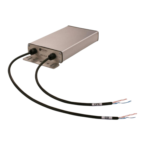
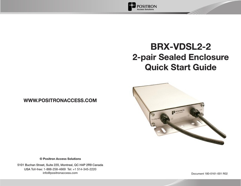
DSLAM BRX-VDSL2-8
L1
Distance from DSLAM to BRX-VDSL2-8
L2
Distance from BRX-VDSL2-8 to CPE
IMPORTANT NOTE: The BRX-VDSL2 unit is powered from the Sealing Current
found on a standard POTS pair. Each pair of the BRX-VDSL2-8 is powered
independently with each pair requiring the presence of the -48Vdc sealing
current for proper operation. The BRX-VDSL2-8 will not operate on a dry pair
(line with no -48Vdc sealing current). You can use the Positron BRX Power
Injector to provide the -48Vdc sealing current when operating on dry pairs.
Connecting the BRX-VDSL2-8
Step 1: Select the location where the BRX-VDSL2-8 will be inserted using the BRX-VDSL2
Calculator for the longest loop that requires amplification.
Step 2: Connect the grounding lug of the unit to a proper ground (usually available near the
splice point).
Step 3: Insert a BRX-BYPASS-TEST module in slot 1 and ensure that both switches are in
BYPASS mode.
Step 4: Connect the first two (2) pairs to be amplified to the first two (2) pairs of the BRX-VDSL2-8.
Make sure to match the DSLAM pair color to the CPE pair color.
Step 5: Test for continuity between the DSLAM pair and CPE pair at the splice point. If a pair
is powered with a -48Vdc sealing current, the corresponding LED on the BRX-BYPASS-TEST
module will be ON. If either circuit is not powered, a continuity test will confirm that the pair is
spliced properly (no open, short or ground fault) but you will need to verify the DSLAM is able
to provide the current. If operating on a dry pair, you should use a BRX Power Injector.
Step 6: Replace the BRX-BYPASS-TEST module with a BRX-VDSL2-M module. The
correspondent DS LED will turn GREEN to confirm presence of -48Vdc sealing current and
proper operation. The US LED currently not used.
Step 7: The DSLAM and CPE will now retrain the circuit and bring up the ADSL2+ / ADSL
link with the amplified bandwidth. The performance may be limited (or capped) by a setting
in the DSLAM and/or BRAS configuration.
Step 8: Repeat steps 3 to 7 for the three (3) slots of the BRX-VDSL2-8
CPE
Placement Guidelines for BRX-VDSL2 Devices
The BRX-VDSL2 amplifies VDSL2 loops and supports profiles 17a, 8a, 8b and 8d. It is
designed to deliver solid amplification of the loops as long as the BRX-VDSL2 device is
installed within 45% to 60% of the total loop distance. It is recommended to install the
BRX-VDSL2 unit at an existing splice point that is within the recommended placement
range. When multiple splice points exist within that range, you should select the one
that is most convenient.
The BRX-VDSL2 installation should follow these simple rules:
1. L1 - Minimum Loop Length from DSLAM to BRX-VDSL2 should be no less than
2000 feet (0.6 km) for 24 AWG (0.5 mm) gauge or 1600 feet (0.5km) for 26 AWG
(0.4 mm) gauge.
2. L2 - Minimum Loop Length from CPE to BRX-VDSL2 should be no less than
650 feet (200m) for 24 AWG (0.5mm) gauge or 500 feet (150m) for 26 AWG (0.4
mm) gauge.
For a 25 / 3 Mbps service, the recommended range is as follows (single pair):
• Maximum total loop length: 6250 feet (1.9 km) for 24 AWG (0.5mm) gauge or
5000 feet (1.5 km) for 26 WG (0.4 mm) gauge.
• Recommended placement range: 3000 to 3600 feet (0.9 to 1.1 km) of 24 AWG
(0.5mm) gauge or 2400 to 2900 feet (0.7 to 0.9 km) of 26 AWG (0.4 mm) gauge.
For a 10 / 1 Mbps service in VDSL2 mode (useful when you want to limit the use of
ADSL2+ loops inside a binder mostly used for VDSL2 loops), the recommended range
is as follows (single pair):
• Maximum total loop length: 10000 feet (3 km) for 24 AWG (0.5mm) gauge or
8000 feet (2.4 km) for 26 WG (0.4 mm) gauge.
• Recommended placement range: 4500 to 5500 feet (1.4 to 1.7 km) of 24 AWG
(0.5mm) gauge or 3600 to 4400 feet (1.1 to 1.3 km) of 26 AWG (0.4 mm) gauge.
Recommended DSLAM Settings
Parameter Downstream Upstream
Maximum Bitrate 100 Mbps 50 Mbps
Maximum Delay 8 msec 8 msec
Path Latency Interleaved
Impulse Noise Protection (INP) 2 1
Target SNR Margin 8.0 dB 8.0 dB
In order to fully benefit from the amplified VDSL2 signal, there are a few DSLAM
settings to be set as per the following recommendation:
You should also make sure that the DSLAM and/or the BRAS settings are not set at a
lower level than the target service offered to the subscriber for this loop.
NOTE: You should always follow your corporate guidelines for the DSLAM settings if
they differ from the Positron recommendation. If in doubt, you should check with the
Engineering or Operation team.
The BRX-VDSL2 Calculator can help determine the optimal installation location for
each specific loop. To download the BRX-VDSL2 Calculator, sign up on the Positron
Access Portal at www.positronaccess.com/Portal.php. You will get a username and
password to access the Portal.
