Document 180-0164-001 R06
Summary Diagram of Typical Installation
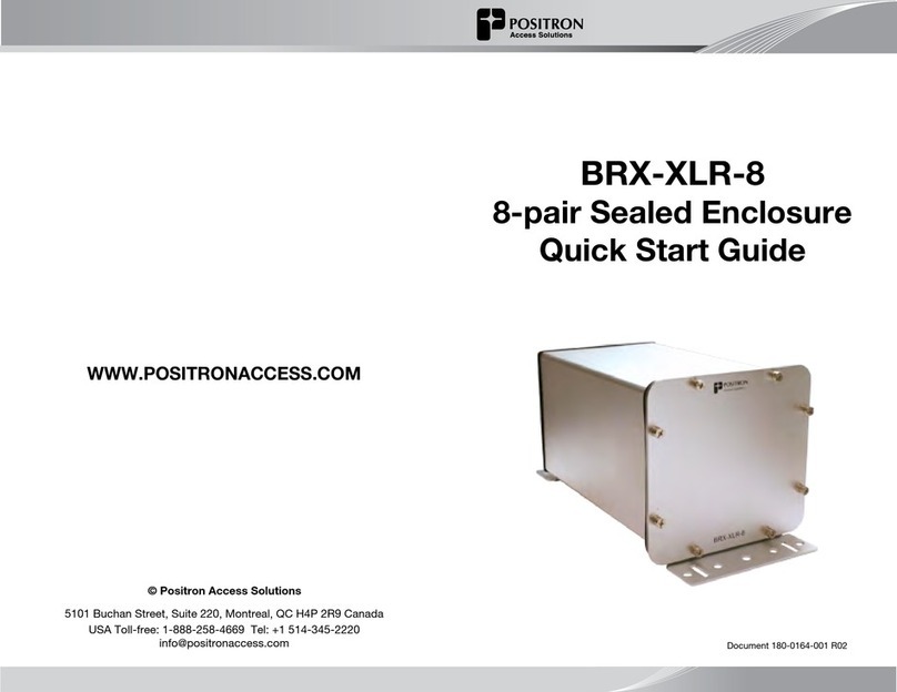
DSLAM BRX-XLR-8
L1
Distance from DSLAM to BRX-XLR-8
L2
Distance from BRX-XLR-8 to CPE
IMPORTANT NOTE: The BRX-XLR unit is powered from the Sealing
Current found on a standard POTS pair. Each pair of the BRX-XLR-8
is powered independently with each pair requiring the presence
of the -48Vdc sealing current for proper operation. The BRX-XLR-8
will not operate on a dry pair (line with no -48Vdc sealing current).
You can use the Positron BRX Power Injector to provide the -48Vdc
sealing current when operating on dry pairs.
Connecting the BRX-XLR-8
Step 1: Select the location where the BRX-XLR-8 will be inserted using the
BRX Cloud Calculator for the longest loop.
Step 2: Connect the grounding lug of the unit to a proper ground (usually
available near the splice point).
Step 3: Insert a BRX-BYPASS-TEST module in slot 1 and ensure that both
switches are in BYPASS mode.
Step 4: Connect the rst two (2) pairs to be amplied to the rst two (2)
pairs of the BRX-XLR-8. Make sure to match the DSLAM pair number to
the CPE pair number.
Step 5: Test for continuity between the DSLAM pair and CPE pair at the
splice point. If the circuits are active, the LEDs on the BRX-BYPASS-TEST
module will be ON to conrm that the sealing current is present on both
lines. If either circuit is not active, the continuity testing will conrm that
the connections are reliable.
Step 6: Replace the BRX-BYPASS-TEST module with a BRX-XLR-M
module.
Step 7: The DSLAM and CPE will now retrain the circuit and bring up the
ADSL2+ / ADSL link with the amplied bandwidth. The performance may
be limited (or capped) by a setting in the DSLAM conguration.
Step 8: Repeat steps 3 to 7 for the other three (3) slots of the BRX-XLR-8
enclosure.
CPE
Placement Guidelines for BRX-XLR Devices
The BRX-XLR amplies ADSL2+ and ADSL loops and is designed to deliver
solid amplication of the loops as long as the BRX-XLR device is installed
within 45% to 75% of the total loop distance. It is recommended to install
the BRX-XLR unit at an existing splice point that is within the recommended
placement range. When multiple splice points exist within that range, you
should select the one that is most convenient.
The BRX-XLR installation should follow these simple rules:
1. L1 - Minimum Loop Length from DSLAM to BRX-XLR should be
no less than 6500 feet (2 km) for 24 AWG (0.5 mm) gauge or 5000 feet
(1.5 km) for 26 AWG (0.4 mm) gauge.
2. L2 - Minimum Loop Length from CPE to BRX-XLR should be no less
than 650 feet (200 m) for 24 AWG (0.5mm) gauge or 500 feet (150 m) for
26 AWG (0.4 mm) gauge.
For a 10 / 1 Mbps service, the recommended range is as follows (single pair):
• Maximum total loop length: 17500 feet (5.3 km) for 24 AWG (0.5mm)
gauge or 12750 feet (3.9 km) for 26 WG (0.4 mm) gauge.
• Recommended placement range: 8000 to 12000 feet (2.4 to 3.6 km)
of 24 AWG (0.5mm) gauge or 5700 to 8900 feet (1.7 to 2.7 km) of 26
AWG (0.4 mm) gauge.
The BRX Cloud Calculator can help determine the optimal installation
location for each specic loop. To access the BRX Cloud Calculator, sign
up on the Positron Access Portal at www.positronaccess.com/Portal.php.
You will get a username and password to access the Portal.
Recommended DSLAM Settings
Parameter Downstream Upstream
Maximum Bitrate 32000 kbps 1296 kbps
Maximum Delay 8 msec 8 msec
Path Latency Interleaved
Impulse Noise Protection (INP) 2 1
Target SNR Margin 6.0 dB 6.0 dB
In order to fully benet from the amplied ADSL2+ / ADSL signal, there are a
few DSLAM settings to be set as per the following recommendation:
You should also make sure that the DSLAM and/or the BRAS settings are not
set at a lower level than the target service offered to the subscriber for this loop.
NOTE: You should always follow your corporate guidelines for the DSLAM
settings if they differ from the Positron recommendation. If in doubt, you
should check with the Engineering or Operation team.
