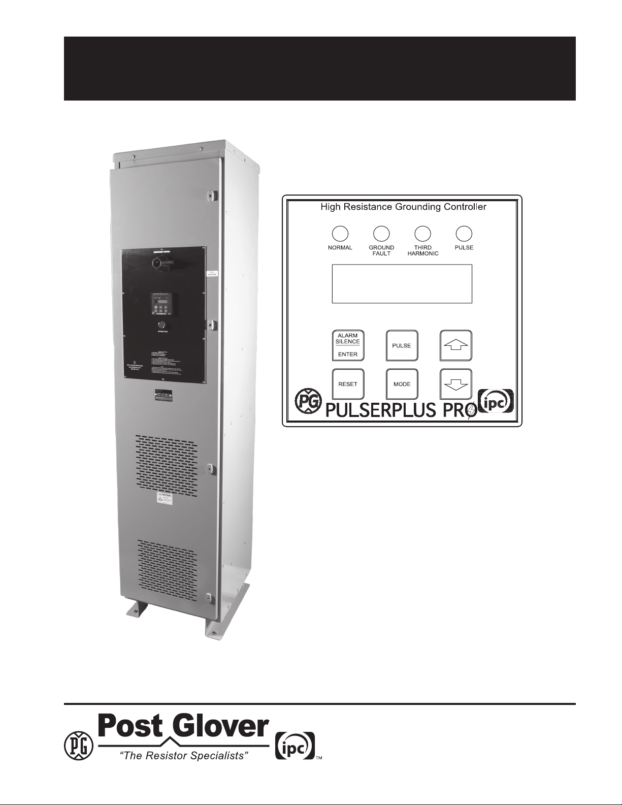
PULSERPLUS PRO™ HIGH RESISTANCE GROUNDING SYSTEM
INSTALLATION, OPERATION AND MAINTENANCE INSTRUCTIONS
4750 Olympic Blvd. • Erlanger, KY 41018 • USA
Phone: 800-537-6144 / 859-283-0778 • Fax: 859-283-2978
www.postglover.com
Serving the Electrical Industry Since 1892
PGR Document #HG111-06© 2006 Post Glover Resistors, Inc.
PULSERPLUS PRO™ HIGH RESISTANCE GROUNDING SYSTEM
INSTALLATION, OPERATION AND MAINTENANCE INSTRUCTIONS
© 2006 Post Glover Resistors, Inc. 2
Table of Contents
Section 1 Equipment Overview........................................................................................... 3
Section 2 Operational Description ...................................................................................... 4
2.1 Normal Operation ............................................................................................... 4
2.2 Loss of Ground ................................................................................................... 4
2.3 Ground Fault ....................................................................................................... 4
2.4 High 3rd Harmonics............................................................................................. 5
2.5 Summary of Events............................................................................................. 6
Section 3 Installation........................................................................................................... 7
3.1 Receiving ............................................................................................................ 7
3.2 Handling.............................................................................................................. 7
3.3 Storage ............................................................................................................... 7
3.4 Floor Preparation ................................................................................................ 7
3.5 Grounding ........................................................................................................... 7
3.6 Line and Control Connections ............................................................................ 8
3.7 Setting Resistor Tap Connections ...................................................................... 8
3.8 General ............................................................................................................... 8
Section 4 Start-up Procedure ............................................................................................. 9
4.1 Energize Circuit................................................................................................... 9
4.2 Entering Setup Information ................................................................................. 9
4.3 Ground Fault Alarm Test..................................................................................... 9
Section 5 System Capacitive-Charging Current................................................................ 11
5.1 General .............................................................................................................. 11
5.2 Test Procedure................................................................................................... 11
5.3 Test Results ....................................................................................................... 13
Section 6 Controller Setup................................................................................................. 14
6.1 Power-up Display ............................................................................................... 14
6.2 Adjustable Parameters ...................................................................................... 14
6.3 CongurationMode ........................................................................................... 15
6.4 Measurement Enable......................................................................................... 15
6.5 Current Transfomer Ratio .................................................................................. 15
6.6 Hi Limit Setpoints............................................................................................... 16
6.7 Lo Limit Setpoints .............................................................................................. 16
6.8 Pulsing Timer ..................................................................................................... 17
6.9 Alarm Delay ....................................................................................................... 17
6.10 Auto Reset ......................................................................................................... 17
Section 7 Locate a Ground Fault ....................................................................................... 18
Section 8 Maintenance ...................................................................................................... 19
Section 9 Schematics & Dimension Drawings................................................................... 20
CAUTION! Before any servicing, replacement of parts, adjustment, or any other work is performed requiring
physical contact with the electrical working components of this unit, power supplies to the unit must be disconnected.