potenza Aura 8 User manual

INTRODUCTION
The Aura 8 Advanced Flight Control System (AFCS) is a powerful, yet exible ight control
system. This Quick Start Guide provides you with basic information to help to get your
airplane in the air for most aircraft. However, advanced aircraft and ight performance
tuning may require additional programming using the Aura PC Programming Application.
To learn about the full capabilities of the Aura 8, as well as access the latest information
and guides, please visit www.exinnovations.com/aura.
CONNECTING A RECEIVER
The Aura 8 supports three separate connection methods - direct connection of up to (2)
DSM2/DSMX remote receivers; data connection for Futaba S.Bus, JR XBus (Mode B),
Graupner HOTT SUMD, Spektrum SRXL; and traditional PWM and PPM connections.
Quick Start programming only supports DSM2/DSMX remote receiver and serial
bus/digital data feeds. Traditional PWM and PPM connections must be congured with the
Aura PC programming app.
I. DSM2/DSMX Remote Receiver(s)
TM
Quick Start Guide
FPZAURA08 | Aura 8 Advanced Flight Control System
Mini Port (B)
Mini Port (A)
DSM2/DSMX Remote Receiver(s) Binding
1. A single remote receiver must always be connected to Mini Port ‘A’. An additional
remote receiver (optional, of matching type) may be plugged into Mini Port ‘B’.
2. Insert a bind plug(s) in Port S8 on the Aura for DSMX remote receiver(s) OR into Ports
S1 and S8 for DSM2 remote receivers.
3. Power the Aura with a 4.0VDC-10.0VDC power source. The LED on the remote
receiver(s) will begin to blink rapidly indicating that the receiver(s) are in bind mode.
4. Put the transmitter in bind mode as described in the instructions in your transmitter
manual. Binding is complete when the remote receiver LED is solid. Remove and store
bind plug(s) to complete the binding process.
II. Serial Bus / Digital Data Receiver
Below are some representative examples of typical serial bus/digital data feed receivers
from major manufacturers. Please note that any serial data/digital data feed receivers
MUST must be bound and properly setup in the transmitter prior to connecting to Aura.
Consult your manufacturer documentation for proper methods and procedures to bind
your receiver.
GRAUPNER SUM D
T
SET
LED
1
No. S1021
GR-16L
2.4GHz
2 3 4 5 6
B B
7 8
Port 8
(typical)
JR XBUS (MODE B)
XBus Port
FUTABA S.BUS
S.Bus/S.Bus2
Port
DSMX SRXL
AUX 1
GEAR
RUDD
ELEV
AILE
THRO
ANT B
ANT L
ANT R
2.4GHz DSM®TECHNOLOGY
HIGH-SPEED 9CH RECEIVER 2048
TECHNOLOGY
WITH TM
SRXL
BATT
AUX 4
AUX 3
AUX 2
BIND/DATA
SRXL
Port
III. Traditional PWM or PPM
Traditional PWM and PPM receiver connections are supported with Aura but must be setup
using the Aura PC Programming app and cannot be setup using the Radio Auto-Detect or
Quick Setup method(s) detailed below.
POWERING AURA 8
Powering the Aura is very exible. The Aura Servo Bus (S1 - S8 and Servo Port B) must be
powered with 4VDC-10VDC. Simple electric models can power the Aura by plugging in the
BEC directly to an Aura Servo Port. Power may also be passed directly from the Receiver to
the Aura. More complex models may use additional connections or ight batteries for
additional redundancy. Several examples are shown below. More examples can be found
at www.exinnovations.com/aura.
WARNING
THE USER MUST PROVIDE AURA WITH A STABLE AND RELIABLE
POWER SUPPLY. FAILURE TO DO SO COULD RESULT IN LOSS OF
CONTROL OR CRASH.
Exercise extreme caution when plugging in any lead that could potentially supply power, or short
power buses. It is possible to 'reverse' or 'short' a power connection by even partially plugging in
a connector. Examples (but not limited to):
§ Connecting multiple batteries or power leads. Use switches, extensions, and Y harnesses
with extreme care.
Check the polarity of each connection carefully. Consult your radio manufacterer’s manual for
information regarding appropriate power supply connections.
DSM2/DSMX REMOTE RECEIVER(S) WITH ESC/BEC
The simplest setup is to provide system power through the ESC/BEC of an electric model.
In the example below, the ESC/BEC is simply plugged into Aura Port S1, making note of the
connection polarity.
ESC/BEC
RECEIVER BATTERY POWER INPUT
If the aircraft is a larger electric or gas powered model, it may need a separate power
source for the motor/engine. In this situation, a receiver battery can be connected directly
to the receiver or the Aura. A matching redundant battery can optionally be added as
shown. If there are not any open Aura ports, a battery may be connected to a servo port
and servo using a Y harness.
ESC
TO RX THROTTLE PORT
TO RX DATA PORT
RECEIVER
BATTERY
TO ANY
AURA PORT
BATTERY
(OPTIONAL)
MOTOR
BATTERY
TO ANY
RX PORT

RADIO AUTO DETECT
Linking the Aura to the receiver is simple for supported radios. The Aura will auto
detect the radio and adjust for the correct input reversing (servos may still require
reversal depending on the linkage geometry of that particular setup), channel order,
etc. Make sure your receiver is bound or linked to your transmitter.
For Aura to receive digital channel data in the correct slots, transmitter Wing
Type must be set to conventional (single aileron) and transmitter Tail Type must
also be set to conventional (single elevator and rudder).
For retrot setups in complex aircraft, it is necessary to change these values
back to default values (as they are in a new/reset model memory): Wing Type,
Tail Type, Servo Reversing. These changes should be made before Auto Detect
has congured Aura to your receiver.
RADIO AUTO DETECT WILL NOT DETECT TRADITIONAL PWM OR PPM
CONNECTIONS.
1. Transmitter travels may be adjusted as required. For good results, transmitter
travel is expected to be between 90% and 140% with 125% being ideal.
2. Make physical connections per the connection diagrams in CONNECTING A
RECEIVER.
3. With the propeller removed (on electric models) and all Aura connections in place,
power on your transmitter, then power your airplane with the ight battery and
keep it stationary. After several seconds, the LEDs will sweep back and forth as the
Aura searches for a valid control signal. Once found, you will see a solid orange
(Aura and sensors are running) and a solid green (Aura is receiving a valid signal)
LED, and you will have control of the model.
Entering Quick Setup Mode
1. Turn on transmitter. With the throttle low, center the rudder/aileron/elevator sticks.
2. Insert bind plug into Aura Port S2.
3. Apply power to Aura and receiver.
If Aura has not detected the radio system being used, auto-detect will run, then quick
setup mode will begin. If you did not intend to enter Quick Setup Mode, remove power
BEFORE unplugging the bind plug to prevent any changes from being saved. Steps 1 & 2
may be adjusted back and forth in any order before continuing to step 3 and saving in
step 4. The orange LED will be o in Quick Setup Mode. The blue, green and red LEDs
will illuminate correspondent to the Quick Setup current settings programmed.
1. Setting Model Type
Two model types can be selected with pre-congured proles that have been crafted over
hundreds of test ights. CH5/Gear switch is used to toggle the model type; high position
will select sport/scale mode and low position will select 3D mode. Check green LED
(second from the right) to conrm you have selected the desired model type.
LED Indication
Green LED On - Sport/Scale Mode
Green LED O- 3D Mode
2. Enabling Master Gain (Optional)
Requires a transmitter proportional input assigned to transmitter Ch8/Aux3
Master gain is OFF upon each entry to Quick Setup mode. Master gain on CH8/Aux3 may
be enabled by sweeping the CH8/AUX3 knob or slider. Check the RED LED (at the far
right) to conrm you have master gain set as intended. If no adjustment is made, master
gain will remain disabled.
LED Indication
Red LED On - Master Gain Enabled
Red LED O - Master Gain Disabled
3. Setting Orientation
Two orientations are available in Quick Setup mode: 'Pins Up' and 'Pins Down'. Both
orientations must have Mini Ports A and B toward the nose of the aircraft. The Aura must
be aligned coincident to the axes of aircraft as shown below. After completing steps 1 and
2 above, place the Aura in the orientation it will be in upright ight before proceeding to
Step 4. Check the Blue LED to conrm the intended orientation.
LED Indication (with aircraft right-side up)
Blue LED On - Aura normal orientation (pins up)
Blue LED O - Aura inverted orientation (pins down)
WARNING
DO NOT ATTEMPT RADIO SETUP WITH PROPELLER INSTALLED.
INADVERTENT POWER UP COULD CAUSE PERSONAL INJURY.
CAUTION
While there is no throttle signal present in quick conguration,
keep the throttle fully idle during setup to avoid damage or injury.
AURA LED LIGHT LAYOUT
RED
GREEN
BLUE
ORANGE
PINS UP PINS DOWN
4. With aircraft upright, remove the bind plug from Aura Port S2 to save the
settings from Steps 1 - 3. If saving the settings for these steps is not desired,
remove power before removing the bind plug.
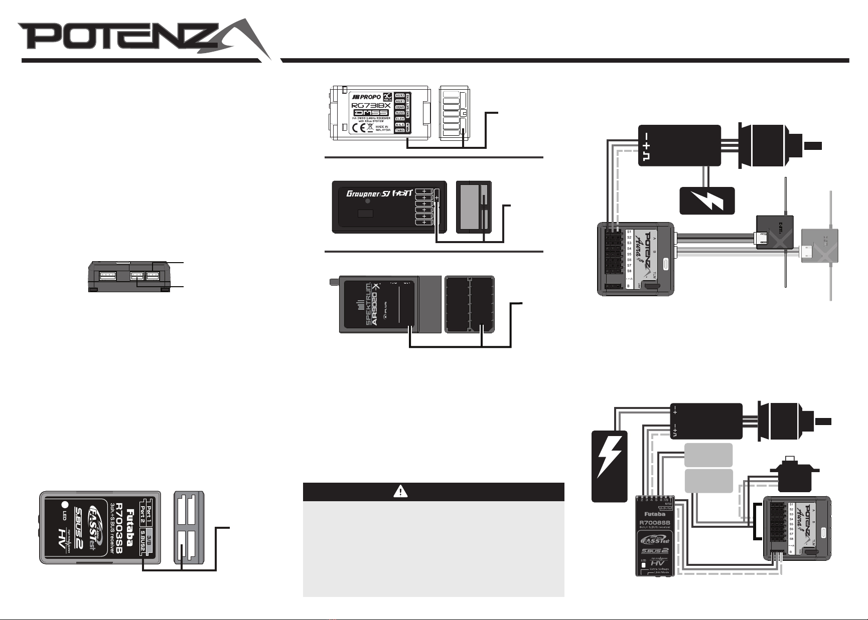
REDUNDANT DSM2/DSMX POWERSAFE SRXL POWER
For redundant power input using a DSM PowerSafe SRXL receiver, simply connect a
two-wire lead from any servo port to any Aura port (S1-S8).
PARALLEL BATTERY POWER
If Aura has no additional ports available for battery power, parallel power may be supplied
by plugging both a servo AND a battery into a single Aura port with a Y-harness. The signal
wire should be removed from the 'power' lead in order to prevent any signal interference.
SIGNAL
POSITIVE
NEGATIVE
NOTICE
If only one aileron servo is being used, it should be connected into Port S3.
If only one elevator servo is being used, it should be connected into Port S4.
Throttle (optional)
Left Aileron
Right Aileron
Left Elevator
Right Elevator (reversed)
Rudder
CH6/AUX1
CH7/AUX2
Any open ports (S1-S8) on Aura
may be used to receive/supply
battery power as required.
CONFIGURE AURA
The Aura must be congured to properly set the servo ports (S1 - S8), gyro gain, etc.
Complex aircraft should be congured using the Aura PC Programming App, however,
many airplanes can be congured at the eld with only a transmitter using the Aura Quick
Setup feature. To use the Quick Setup feature, the airplane must meet the following
criteria:
1.
Digital receiver data feed, including any of these:
§
DSM2/DSMX remote receivers or SRXL connection
§
Futaba S.Bus
§
JR DMSS XBus (Mode B)
§
Graupner HOTT Sum D of 8
2.
Conventional tail type (single elevator/rudder servo or matched pair with single input)
OR dual elevator servos with reversed mounting direction for each servo.
3.
Conventional wing type using one or two aileron servos (or more if one or two inputs
are used with Y-harnesses or servo matching device such as JR MatchBoxes)
4. Aura mounted with Mini Ports A & B oriented towards the nose of the aircraft. Pins for
Ports S1-S8 may be oriented upright or inverted. (see instructions below)
5. CH5/Gear assigned to a 3-position switch (preferred) on the transmitter. A 2-position
switch may be used, but Aura will be limited to (2) ight modes.
If your airplane adheres to the criteria above, follow the steps below to setup your airplane
with the Aura 8 quickly at the eld using Quick Setup mode and your transmitter.
Quick Setup mode is not recommended for retrotting your an Aura 8 into complex
aircraft such as those with multiple servo wing types or aps. The Aura PC
Programming App is more exible and eective for complex aircraft.
AURA QUICK SETUP (VIA TRANSMITTER)
Quick Setup Servo Connections
2.4GHz DSM®TECHNOLOGY
HIGH-SPEED 12CH RECEIVER 2048
AUX 6 SRXL SWITCH AUX 7
TM
BND/DAT
AUX 5
AUX4
AUX3
AUX2
AUX1
GEAR
RUDD
ELEV
AILE
THRO
BATT1 BATT2
B
R
A
L
TO ANY AURA PORT TO ANY RX PORT
OPTIONAL CONNECTION FOR REDUNDANT POWER
TO SRXL PORT

© 2015 Flex Innovations, Inc.
Premier Aircraft™, Potenza™, and Top Value RC™ are trademarks or registered trademarks of Flex Innovations, Inc.
Android is a trademark of Google Inc. iPhone® is a trademark of Apple Inc registered in the US and other countries.
JR and DMSS are registered trademarks of Japan Remote Control Co., Ltd.
DSM®, DSM2™, and DSMX™ are trademarks of Horizon Hobby, Inc.
Futaba is a registered trademark of Futaba Denshi Kogyo Kabushiki Kaisha Corporation of Japan.
HoTT is a registered trademark of SJ, Inc.
Created 8/2015
INNOVATIONS
TM
QUICK TRIM
The Aura 8 features a Quick Trim Mode that eliminates the need for mechanical
linkage adjustments during test ights. Aura will learn the trim values and apply
them to the control surfaces at power up when enabling quick trim mode. While it
is always best to mechanically trim your aircraft so no transmitter trims are required,
sometimes elecronic trim is unavoidable.
NOTE: Quick trim can also be used BEFORE ying to make small changes to
center the control surfaces before ight.
To setup quick trim:
1.
Fly the airplane in manual (gyro o) mode. Trim the aircraft with the transmitter
and land. Do not change ight modes.
2. Power o the Aura. Insert a bind plug into Aura Port S3. Check the transmitter is
on and repower the Aura.
3. Wait 5 seconds for the Aura to completely initialize. Conrm Quick Trim mode is
active by checking the Blue LED is slowly ashing.
4. Remove the bind plug from Aura Port S3. Removing the bind plug stores the
current trims in the Aura. The Blue LED will ash quickly after control surface trim
values are stored. While the trim values are stored in Aura, they are not applied to
the control surface until the Aura is repowered.
5. Remove power from the Aura and center all control surface trims on the
transmitter.
6. Repower the Aura. The control surfaces should be unchanged even though the
trim has been centered on the Transmitter. Switch between other Flight Modes to
ensure you do not see any changes in trim.
NOTE: QUICK TRIM MAY BE REPEATED AS NEEDED FOR FINE
TUNING, OR IF CHANGES TO THE AIRCRAFT ARE MADE.
NOTE: ENSURE AILERON/ELEVATOR/RUDDER SUB TRIMS
ARE ZERO BEFORE FLYING FOR QUICK TRIM PROCESS.
5. Reversing Servo Direction
1. Perform the transmitter command check to verify control surface movement
correspondent to the control direction test chart below.
2. If reversing is required on aileron, elevator, or rudder, hold full stick deection for that
channel in any direction for a minimum of four seconds, at which point the channel
will reverse. This process may be repeated as required for each channel. Servo
reversing changes are saved automatically.
Throttle is not reversible in the Aura. If your model requires throttle
channel reversing, it must be done in the transmitter.
AILERONRUDDER ELEVATOR
Transmitter
Command
Proper Control
Surface Deection
Stick Left
Stick Right
Stick Forward
Stick Aft
Stick Left
Stick Right
6. Sensor Check
Rotate the airplane about each axis, 15° minimum. Use sensor check diagram below to
verify that control surface moves in the correct direction to counter the motion. During
Quick Setup mode, a special control mode executes and makes checking the sensor
direction easier. Moving the sticks will reset the control surfaces to center, if required.
If any of the axes fail the control sensor check but responds correctly to the transmitter
commands, check the transmitter's programming and ensure that all the directions are
set to NORMAL. Repeat the transmitter command test and sensor check until all surfaces
move as intended.
Aircraft
Movement
Proper Control
Surface Deection
AILERONRUDDER ELEVATOR
7. Exiting Quick Setup Mode
Exit Quick Setup mode by removing power from the Aura. Conrm the bind plug has
been removed from S2 prior to repowering the Aura. You must power down the Aura
to exit Quick Setup mode before ying.
Repeat all control direction and sensing direction tests in normal mode (in highest
gain setting) before ying. If any anomalies exist, correct before attempting ight.
In quick setup mode steps 5 and 6, if the airplane and transmitter are left unattended
for a period of time, the sensor may accumulate errors and may move the control
surfaces. Simply move the transmitter sticks to reset. NOTE- this only happens in
quick setup conguration mode, and will not occur in normal (ying) mode.
TMTM
Quick Start Guide (Continued)
This manual suits for next models
1