Supplied By www.heating spares.co Tel. 0161 620 6677
Publication No. 5102696 9InstallationRequirements
1.9 The System
Beforeinstallinganewboilertoanexistingsystemtreatthe
systemwithanappropriatedescaling/flushingagentasper
the instructions supplied with the treatment package. It is
recommendedthatanycorrosioninhibitorsanddescalers/
flushing agents used are manufactured by Fernox or
BetzDearborn.
If plastic pipe is used for the central heating circuit there
mustbearunofatleast2mofuninsulatedcopperpipefrom
theboiler flowandreturn connections.
TheboilermustbeusedonIndirectFullyPumpedsystems
only, which may be sealed or open vented - See Page 12
forpumprequirements.
Thesystemshouldbedesignedsothatthemaximumstatic
headdoesnotexceed30.5m(100ft)andaminimumof150
mm(6in).Theflowpipefromtheboilermustalwaysbelevel
toorhigherthanthereturn pipe.
On all systems the pump live connection should be wired
tothe boiler terminal block,itwill then becontrolledbythe
pumpover-run.Thiswillensurethatthepumpwillcontinue
torunafterboilershutdownifthewatertemperatureishigh,
thus preventing nuisance operation of the overheat
thermostat.
Itisimportantthatwhereelectricallyoperatedzonevalves
are used the boiler is wired so it does not cycle when the
zone valves are closed. Also, systems fitted with controls
thatclosebothhotwaterandcentralheatingcircuitswhile
theboiler isstillhot, mustbefitted withaby-pass circuitto
dissipate the residual heat from within the boiler.
IfathreeportvalveisusedasshowninFig.5aby-passis
not necessary since one circuit is always open.
Where a pair of two port valves are used, a by-pass is
necessary. The total length of the by-pass circuit taken
fromtheboilerconnectionsshouldbegreaterthan4metres
of22mmpipe.Itshouldbefittedwithalockshieldvalveand
beadjustedtomaintainaminimumflowthroughtheboiler
of 4.5 litres/min (1 gal/min).
Systems fitted with controls which allow the boiler to
operatewhenboththehotwaterandcentralheatingcircuits
areclosed(i.e.mechanicallyoperatedthermostaticcontrol
valves)mustbefittedwithaby-passcircuit(2mmin.length
of22mmdia.pipe)andcapableofmaintainingaminimum
waterflowratethroughtheboilerof9litres/min(2gal/min).
A suggested method of meeting these requirements by
usingabathroomradiatorfittedwithtwolockshieldvalves
is shown in Fig. 5. Additional system information can be
foundintheControlSystems,pipeworkandWiringGuide.
Drain off taps should be fitted in the pipework close to the
boiler and in the low points of the system.
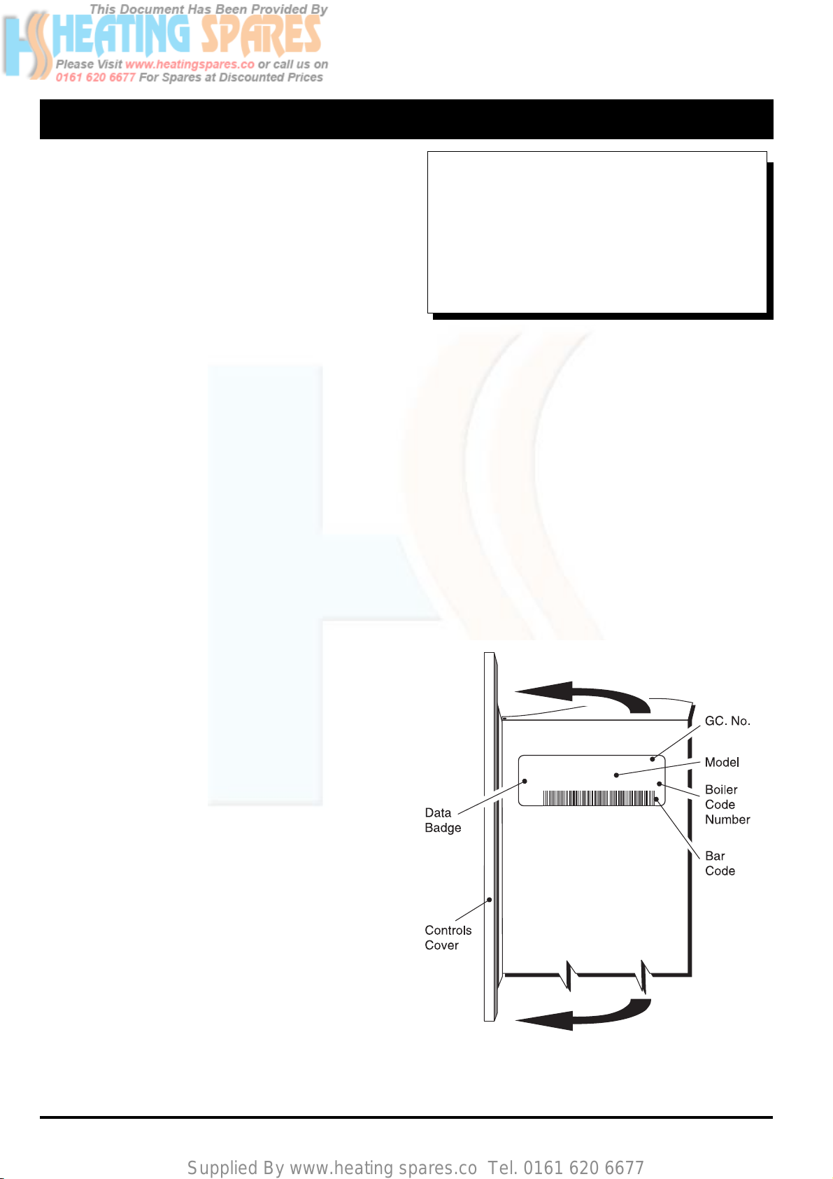
Note:Althoughthesystemcanbeemptiedusingthedrain
off taps installed in the pipework around the system, to
empty the boiler it is necessary to remove the drain off
screwpositioned ontheheatexchanger.
Sealed Systems
Note: If the sealed system kit is
Not
being used the
installation must comply with the following requirements.
Installation
The installation must comply with the requirements of BS
6798:1987andBS5449:Pt1.TheBritishGaspublication
"BritishGasSpecificationforDomesticWetCentralHeating
Systems" should also be consulted.
PressureReliefValve
Anon-adjustablespring-loadedpressurerelief valve,preset
tooperateat3bar(45lbf/in²)shallbeused.Itmust comply
withBS 6759: Pt1. and includeamanual testingdevice.It
shall be positioned in the flow pipe either horizontally or
verticallyupwardsandclosetotheboiler.Noshut-offvalves
aretobeplacedbetweentheboilerandthesafetyvalve.The
valve should be installed with a discharge pipe which
permitsthesafedischargeofsteamandhotwatersuchthat
nohazardto persons or damage to electricalcomponents
is caused.
PressureGauge
A pressure gauge incorporating a fill pressure indicator,
coveringtherange0-4bar(60lbf/in²)shallbefittedtothe
system.Itshouldbeconnectedtothesystem,preferablyat
thesamepointastheexpansionvessel.Itslocationshould
be visible from the filling point.
ExpansionVessel
AdiaphragmtypeexpansionvesseltoBS4814:Pt1.shall
befittedclosetotheinletsideofthepump.Theconnecting
pipework should not be less than 15 mm. Pipework
connecting the expansion vessel should not incorporate
valves of any sort. Methods of supporting the vessel are
supplied by the vessel manufacturer. The nitrogen or air
charge pressure of the expansion vessel shall not be less
than the hydrostatic head, (height of the top point of the
systemabovetheexpansionvessel).Tosizetheexpansion
vesselit is first necessarytocalculate the volume ofwater
inthesysteminlitres. Thefollowing volumesmay beused
asaconservative guide to calculating the system volume.
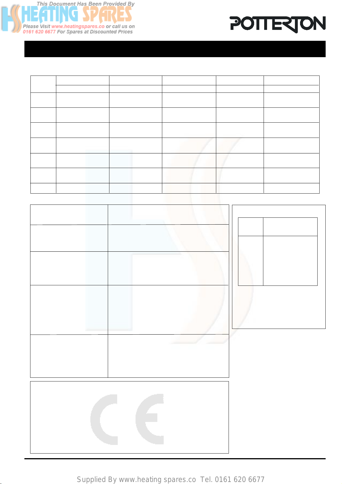
BoilerHeatExchanger: 2.1 litres
SmallBorePipework: 1 litre per kW of system
output
MicroBorePipework: 7 litres
SteelPanelRadiators: 8 litres per kW of system
output
LowWaterCapacityRadiators: 2 litres per kW of system
output
HotWaterCylinder: 2 litres