manuals.online logo
Brands
  1. Home
  2. •
  3. Brands
  4. •
  5. Potterton
  6. •
  7. Boiler
  8. •
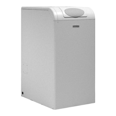
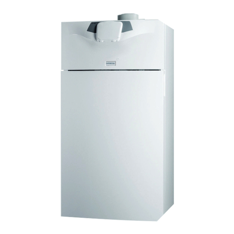
  9. Potterton Profile User guide

Potterton Profile User guide

Other Potterton Boiler manuals

Potterton Lynx Electronic User manual

Potterton

Potterton Lynx Electronic User manual

Potterton Performa 24 Eco HE User manual

Potterton

Potterton Performa 24 Eco HE User manual

Potterton Suprima 30 HE Instruction Manual

Potterton

Potterton Suprima 30 HE Instruction Manual

Potterton BOA 68 Operating manual

Potterton

Potterton BOA 68 Operating manual

Potterton LPG 50e User manual

Potterton

Potterton LPG 50e User manual

Potterton Sirius two WH Manual

Potterton

Potterton Sirius two WH Manual

Potterton Sirius two WH 90 Guide

Potterton

Potterton Sirius two WH 90 Guide

Potterton Statesman 45/50 Installation and maintenance instructions

Potterton

Potterton Statesman 45/50 Installation and maintenance instructions

Potterton Performa System HE User manual

Potterton

Potterton Performa System HE User manual

Potterton 40eL User manual

Potterton

Potterton 40eL User manual

Potterton Performa 30 HE User manual

Potterton

Potterton Performa 30 HE User manual

Potterton Derwent Prestige plus Instruction manual

Potterton

Potterton Derwent Prestige plus Instruction manual

Potterton Envoy Flowsure Installation and maintenance instructions

Potterton

Potterton Envoy Flowsure Installation and maintenance instructions

Potterton Gold HE A Range Installation and maintenance instructions

Potterton

Potterton Gold HE A Range Installation and maintenance instructions

Potterton 360 User guide

Potterton

Potterton 360 User guide

Potterton Statesman 50/70L Installation and maintenance instructions

Potterton

Potterton Statesman 50/70L Installation and maintenance instructions

Potterton Promax 24 Combi ErP Manual

Potterton

Potterton Promax 24 Combi ErP Manual

Potterton Suprima 80 HE Installation and maintenance instructions

Potterton

Potterton Suprima 80 HE Installation and maintenance instructions

Potterton iHE 150 Release note

Potterton

Potterton iHE 150 Release note

Potterton Performa 28 Operation instructions

Potterton

Potterton Performa 28 Operation instructions

Potterton NXR5i User manual

Potterton

Potterton NXR5i User manual

Potterton Performa 28 User manual

Potterton

Potterton Performa 28 User manual

Potterton Prorile Prima 30e User guide

Potterton

Potterton Prorile Prima 30e User guide

Potterton Performa 24 Eco HE Installation and maintenance instructions

Potterton

Potterton Performa 24 Eco HE Installation and maintenance instructions

Popular Boiler manuals by other brands

IDEAL IMAX XTRA EL 320 user guide

IDEAL

IDEAL IMAX XTRA EL 320 user guide

UTICA BOILERS BC3D Installation, operation & maintenance manual

UTICA BOILERS

UTICA BOILERS BC3D Installation, operation & maintenance manual

Lochinvar SOLUTION 260000 Installation & service manual

Lochinvar

Lochinvar SOLUTION 260000 Installation & service manual

Weil-McLain EG 6 Series manual

Weil-McLain

Weil-McLain EG 6 Series manual

RBI LCD Series Installation & operation manual

RBI

RBI LCD Series Installation & operation manual

Baxi MainEco Combi 28 Installation and service manual

Baxi

Baxi MainEco Combi 28 Installation and service manual

Unical ALKON R 24 Installation and Servicing Manual

Unical

Unical ALKON R 24 Installation and Servicing Manual

Automatic Heating Gasogen Installation and Servicing Manual

Automatic Heating

Automatic Heating Gasogen Installation and Servicing Manual

Viessmann VITORADIAL 300-T Type VR3 Service instructions for contractors

Viessmann

Viessmann VITORADIAL 300-T Type VR3 Service instructions for contractors

Alpha GasSaver GS-1 Installation and servicing instructions

Alpha

Alpha GasSaver GS-1 Installation and servicing instructions

Baxi ROCA LAURA PLUS 28/28 Operating, cleaning and maintenance instructions for the user

Baxi

Baxi ROCA LAURA PLUS 28/28 Operating, cleaning and maintenance instructions for the user

Vaillant uniSTOR VIH SW GB 500 BES operating instructions

Vaillant

Vaillant uniSTOR VIH SW GB 500 BES operating instructions

Kärcher HWE 4000 Gas manual

Kärcher

Kärcher HWE 4000 Gas manual

Radijator BIO max 23.1 instruction manual

Radijator

Radijator BIO max 23.1 instruction manual

Granby BKC Installation, operation and maintenance manual

Granby

Granby BKC Installation, operation and maintenance manual

Brunner BSV 20 Instructions for use

Brunner

Brunner BSV 20 Instructions for use

UTICA BOILERS TriFire Assembly instructions

UTICA BOILERS

UTICA BOILERS TriFire Assembly instructions

ECR International UB90-125 Installation, operation & maintenance manual

ECR International

ECR International UB90-125 Installation, operation & maintenance manual

manuals.online logo
manuals.online logoBrands
  • About & Mission
  • Contact us
  • Privacy Policy
  • Terms and Conditions

Copyright 2025 Manuals.Online. All Rights Reserved.

Supplied By www.heating spares.co Tel. 0161 620 6677
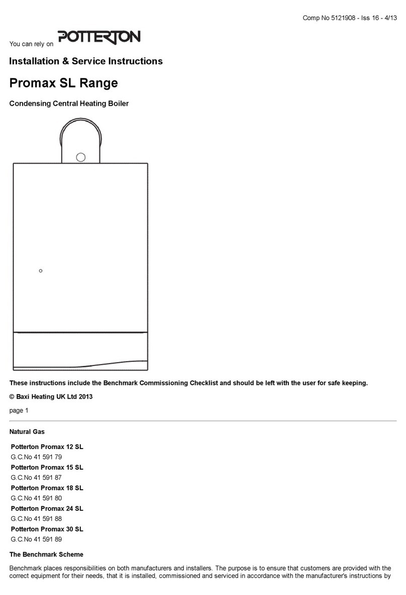
lOOe, fanned balanced flue gas fired boiler
THIS APPLIANCE IS FOR USE WITH NATURAL GAS (G20) ONLY
Installation and Servicing Instructions
LEAVE THESE INSTRUCTIONS ADJACENT TO THE GAS METER
Supplied By www.heating spares.co Tel. 0161 620 6677
2
GAD (90/396/EEC)
POTTERTON PROFILE lOOe G.C. No. 41 -607-49 (S.I.T. Control Valve)
POTTERTON PROFILE lOOe G.C. No. 41-605-65 (White Rodgers Control Valve)
IMPORTANT This appliance must be installed and serviced by a competent person as stated in the Gas Safety (Installation
and Use) Regulations 1994.
Profile boilers are certified for safety, it is therefore important that no external control devices (e.g. flue dampers,
economisers, etc.) be directly connected to these appliances unless covered by these installation instructions or otherwise
recommended in writing. Any direct connection of a control device not approved by Potterton could invalidate the certificate
and the normal warranty.
LIST OF CONTENTS - Page 2
General
Optional Extras
Accessories
Installation Data
Boiler Dimensions
Page No. 2
Page No. 2
Page No. 3
Page No. 3
Page No. 3
Site Requirements
Technical Data
Installation Instructions
Commissioning
Health and Safely Information
Control Systems, Pipework and
Wiring Guide
User’s Instructions
Page No. 3
Page No. 6
Page No. 11
Page No. 18
Back Page
Supplied in
Literature Pack
GENERAL - Page 2
This Potterton Profile boiler is a fully automatically
controlled wall mounted fan powered balanced
flue appliance, using a cast iron heat exchanger
and is range rated from 23.44-29.3kW (80,000-
100,000 Btu/h) output.
The boiler which is designed to provide domestic
hot water and/or central heating must be used on
INDIRECT hot water systems only. The cast iron
heat exchanger, is suitable for use on open
vented gravity domestic hot water/pumped central
heating systems or fully pumped systems which
may be sealed or open vented.
The boiler can be supplied with either of the following types
of flue system, these are packaged with the terminal and
associated flue components.
1) Standard Horizontal flue system Part No. 225542.
Suitable for a wall thickness from 100mm (4in.) to 51
0mm (2Oin.).
2) 1 metre horizontal flue system Part No. 225545. Which
provides a maximum flue length of 955mm (37 in.).
3) 1 metre vertical flue system Part No. 213050. Which
allows the flue to pass through a flat roof and terminate
at a maximum height of 980mm (38in.) measured from
top of the boiler case.
OPTIONAL EXTRAS - Page 2
The following are kits available as optional
extras:-
Internal Fitment Kit, Part No. 225184, which is
suitable for a maximum wall thickness of 510mm
(2Oin.) is to be used where access to the outside
wall is impracticable.
Pump Cover Kit, located on top of the boiler and
designed to conceal the pump, and/or any
motorised valves installed above the boiler (Note:
Pump cannot be fitted above the boiler if the
vertical flue kit is used).
The following sizes are available:-
6in. Part No.225418
7in. - l2in. Part No. 225419
l3in. - l8in. Part No. 225420
l9in. - 24in. Part No.225421
Terminal Wall Plate, Part No. 212280, where necessary
can be fitted to the outside wall face to improve the
appearance, after making good around the terminal.
Terminal Guard, Part No. 205792, to be used when the
terminal is fitted less than 2m above a balcony, above
ground or above a flat roof to which people have access.
Supplied By www.heating spares.co Tel. 0161 620 6677
3
ACCESSORIES - Page 3
The following range of Potterton system controls are
also available and further information will be
provided on request.
Electronic Programmer E.P. 2001, E.P. 3001, E.P.
4001, E.P. 6000.
Programmable Electronic Thermostat PET 1.
Thermostatic Radiator Valve Myson
Electronic Cylinder Thermostat PTT2
Electronic Room Thermostat PRT2
Spring Return Zone Valve PMV2
Spring Return Diverter Valve PMV3
INSTALLATION DATA - Page 3
The installation of the boiler must be in accordance
with the latest relevant requirements of the Gas
Safety (Installation and Use) Regulations, local
building regulations, lEE Wiring Regulations and the
Byelaws of the Local Water Undertaking.
Detailed recommendations are contained in the
following British Standards and Codes of Practice.
B56798, B55440 Part 1
B55440 Part 2 B55449 Part1
BS5546 B54814. B56891.
BUILDING REGULATIONS.
MODEL WATER BYELAWS.
BRITISH GAS PUBLICATION DM2.
GAS SAFETY (INSTALLATION AND USE)
REGULATIONS.
BUILDING STANDARDS (SCOTLAND)
REGULATIONS.
BOILER DIMENSIONS - Page 3
SITE REQUIREMENTS - Page 3
The boiler is not suitable for external installation and
should not be fitted directly above a cooking
appliance. The boiler m be installed in any room,
although particular attention is drawn to the
requirements of the current I.E.E. Wiring Regulations
and in Scotland, the electrical provisions of the
Building Standards applicable in Scotland with
respect to the installation of the
appliance in a room containing a bath or shower.
Where a room-sealed appliance is installed in a room
containing a bath or shower, any electrical switch or
appliance control, utilising mains electricity should be so
situated that it cannot be touched by a person using the
bath or shower.
Supplied By www.heating spares.co Tel. 0161 620 6677
4
Site Requirements - Page 4
FIG. 2 GENERAL ARRANGEMENT
Supplied By www.heating spares.co Tel. 0161 620 6677
5
Site Requirements - Page 5
Where the installation of the boiler will be in an unusual
location, special procedures may be necessary and BS
6798 gives detailed guidance on this aspect.
Ensure that the gas supply pipe and meter are large
enough for this appliance and any others that may be run
off the same meter. Reference should be made to
B56891.
Boiler Mounting Surfaces
The boiler must be mounted on a flat wall, which may be of
combustible material and must be sufficiently robust to take
the weight of the boiler. The requirements of the local
authorities and the building Regulations must be adhered
to.
IMPORTANT NOTICE:
TIMBER FRAMED HOUSES
If the appliance is to be fitted in a timber framed building, it
should be fitted in accordance with British Gas Publication
‘Operational Procedures for Customer Service’ Part 19. If
in any doubt, advice should be sought from the local region
of British Gas.
Clearances Around the Boiler
The following minimum clearances must be maintained
after installation, for correct operation and servicing of the
boiler:
610mm (2 ft) at the front of the boiler
5mm (0.2 in) each side of the boiler
50mm (2 in) at the top (measured from the top of the boiler
case), except where the optional extra pump cover is to be
fitted, when 178mm (7 in) should be allowed.
100mm (4 in) at the bottom of the boiler.
Additional clearances to these are required during
installation for lifting the boiler and 127mm (5 in) is required
at the top of the boiler for access to the pipe connections.
Ventilation
If the boiler is to be installed in a confined space such as a
cupboard, the space will need ventilating. Openings must be
provided at the top and bottom of the cupboard each of
which should have a free area of 349 cm2, (54 in2). Further
details for installation of a boiler within a compartment are
giving in BS 6798.
If the openings draw air from outside the building the free
areas may be halved. Refer to BS 54401 Part 2 for further
guidance.
Balanced Flue Terminal and Ducting
The fresh air inlet and flue ducts can be run from either the
left, right, rear or top of the boiler to a miniature terminal on
the outside of the building.
The minimum spacings from the terminal to obstructions
and ventilation openings as shown in FIG. 3.. For
information appertaining to horizontal flue lengths
reference should be made to FIG. 4.
If a terminal is fitted less than 2m above a balcony, above
ground or above a flat roof to which people have access
then a suitable terminal guard should be fitted (P.l.L No.
205792).
Refer to B55440 Part 1 for further guidance.
Fig. 3 THE SITING OF BALANCED
FLUE TERMINALS
INFORMATION RELATING TO VERTICAL FLUING IS
PROVIDED WITH THE VERTICAL FLUE SYSTEM
PACK.
NOTE
Where a flue terminal is fitted less than 1000 from a plastic
or painted gutter or 500mm from painted eaves, an
aluminium sheild of 1000 length should be fitted to
underside of gutter or eaves.
Any car port or other add-on extension should consist of a
roof or a roof and one other wall. If it consists of a roof and
two other walls — the installation shall be treated as suspect
and further advice sought.
POSITION MINIMUM DISTANCE
mm
A. DIRECTLY BELOW AN OPENABLE
WINDOW, AIR VENT, OR ANY OTHER
VENTILATION OPENING. 300
B. BELOW GUTTER, DRAIN/SOIL PIPE 75
C. BELOW EAVES 200
D. BELOW A BALCONY OR CAR PORT ROOF 200
E. FROM VERTICAL DRAIN PIPES AND
SOIL PIPE 75
F. FROM INTERNAL OR EXTERNAL CORNERS 300
G. ABOVE ADJACENT GROUND OR BALCONY
LEVEL 300
H. FROM A SURFACE FACING THE TERMINAL 600
I. FACING TERMINALS 1,200
J. FROM OPENING (DOOR/WINDOW) IN
CARPOT INTO DWELLING 1,200
K. VERTICALLY FROM A TERMINAL ON
THE SAME WALL 1,500
LHORIZONTALLY FROM A TERMINAL ON
THE SAME WALL 300
M. ADJACENT TO OPENING 150
Supplied By www.heating spares.co Tel. 0161 620 6677
6
REAR OR SIDE FLUEING - Page 6
FIG. 4 FLUE LENGTHS
MAXIMUM
LENGTH ‘X’
STANDARD FLUE
SYSTEM 510mm
(20in)
1 METRE FLUE
SYSTEM 955mm
(37in)
ELECTRICITY SUPPLY
A 240 volts ~ 50Hz, single phase electricity supply
fused to 3 amperes, must be provided in accordance
with the latest edition of the I.E.E. Wiring Regulations
and any other local regulations that may apply. The
current rating of the wiring to the boiler must exceed 3
amperes and have a cross sectional area of at least
0.75mm2 in accordance with BS 6500. Table 16.
The supply to the boiler and its associated
equipment should be controlled by a 3A fused
double pole switch (having at least 3mm contact
separation in both poles) so that complete isolation
from the supply can be achieved to enable servicing
work to be carried out in safety.
TECHNICAL DATA - Page 6
Maximum working head 30.5m (100 ft) Power consumption 80 watts
(excluding pump)
Minimum working head on
Fully Pumped systems 305mm (1 ft) Flow/Return connection 28mm copper
Minimum circulating head Gas supply connection Rc. 1/2 (1/2 in BSP
on Gravity systems 1.2m (4 ft) Female)
Gas supply pressure 20mbar Water Content 6.5 litre (1.43 gal)
Maximum Flow temperature 82ºCAppliance Weight-installed 63.5kg (140 Ibs)
Electricity supply 240v ~ 50Hz fused Appliance Weight-lift 54.5kg (120 Ibs)
at 3A
Internal Fuse T1A
Supplied By www.heating spares.co Tel. 0161 620 6677
7
Technical Data - Page 7
INJECTOR
SIZE GAS RATE
m3/h (ft3/h) INPUT
kW(Btu/h) OUTPUT
kW(Btu/h) BURNER PRESSURE
mbar in wg
Min
Max
4.9mm 3.00(105.9)
3.31(117.0)
3.62(128.0)
32.1(109500)
35.4(121000)
38.8(132500)
23.5(80000)
26.4(90000)
29.3(100000)
10.0
12.0
14.0
4.0
4.8
5.6
CIRCULATION PUMP SELECTION
The resistance through the heat exchanger when operating
with a water flow rate producing an 11 0C temperature riseat
maximum boiler output are shown in TABLE 2. If other
controls, such as three-position valves are used in the
system, the resistance through them, quoted in their
manufacturer’s literature must be taken into account. The
pump may be fitted on either the flow or return and MUST
be wired directly to the boiler terminal block, see FIG. 24. It
must be fitted with two isolating valves which are positioned
as close to the pump as possible. Closing of any valve must
always leave the open vent unobstructed.
TABLE 2
WATER FLOW RATE BOILER RESISTANCE
WITH DISC WITHOUT DISC
litres/sec gal/min KN/m2 in wg KN/m2 in wg
0.637 8.4 17.8 72 5.2 21
NOTE: Great care should be taken when selecting a
pump to ensure that the correct flow rate is achieved.
Fully pumped systems should be designed so that the
system differential is no greater than 15ºC.
FIG. 5 PRESSURE LOSS ACROSS BOILER
Supplied By www.heating spares.co Tel. 0161 620 6677
8
Technical Data - Page 8
The System
The boiler must be used on INDIRECT hot water systems only. It is
suitable for use on open vented gravity domestic hot water/pumped
central heating systems or, fully pumped systems which are open
vented.
The system should be designed so that the maximum static head
does not exceed 30.5 m (lOOft) and a minimum on fully pumped
systems of 305 mm (1 ft). See FIG. 6.
Gravity domestic hot water circuits should have a minimum
circulating head of 1.2 m (4ft). See FIG. 8.
To ensure optimum boiler performance on both gravity hot water
and fully pumped systems a change-over switch is incorporated in
the boiler control box. The boiler is supplied with the switch set for
sealed or open vented fully pumped systems.
If the boiler is to be used on a system with gravity hot water the
switch should be set at the GRAVITY position. In addition the bulb
of the overheat thermostat should be repositioned as shown in
FIG. 21 b.
To prevent reverse circulation in the gravity circuit when the pump
is running an injector disc is provided to form an injector tee at the
return connection on the boiler. See FIG. 20.
On all systems the pump should be wired to the boiler terminal
block. To prevent nuisance operation of the overheat thermostat, it
is important that where electrically operated zone valves are used
the boiler is wired so it does not cycle when the zone valves are
closed. Also, systems fitted with controls that close both hot water
and central heating circuits while the boiler is still hot, must be fitted
with a by-pass circuit to dissipate the residual heat within the boiler.
Further information on by-pass arrangements is provided in later
notes and illustrations.
Drain off taps should be fitted in the pipework close to the boiler
and in the low points of the system.
Note: Although the system can be emptied using the drain off taps
installed in the pipework around the system, to empty the boiler it is
necessary to remove the drain off cap positioned within the boiler
case. See FIG. 2.
Combined Gravity Hot Water Pumped Central Heating
Systems. Where a cylinder thermostat and zone valve is used to
control the temperature of the hot water it is recommended that a
by-pass by installed in the gravity circuit. A suggested method of
doing this is shown in FIG. 8 where the bathroom radiator is
connected into the gravity circuit and is fitted with two lockshield
valves. Mechanically operated thermostatic domestic hot water
temperature control valves which allow the boiler to operate when
the valve is closed or partially closed MUST NOT BE FITTED.
Fully pumped Systems
NOTE: Great care should be taken when selecting a pump to
ensure that the correct flow rate is achieved. Fully pumped systems
should be designed so that the system differential is no greater than
15ºC.
With the change-over switch in the control box set at the FULLY
PUMPED position, the pump will be controlled by an over-run
thermostat. This will ensure that the pump will continue to run after
boiler shut down if the water temperature in the boiler is high. If a
three port diverter valve is used as shown in FIG. 6, a by-pass is
not necessary since one circuit is always open.
temperature in the boiler is high, thus preventing nuisance
operation of the overheat thermostat. If a three port diverter
valve is used as shown in FIG. 6, a by-pass is not necessary
since one circuit is always open.
Where a pair of two port valves are used, a by-pass is
necessary. The total length of the by-pass circuit taken from the
boiler connections should be greater than 4 metres of 22 mm
pipe. It should be fitted with a lockshield valve and be adjusted to
maintain a minimum flow through the boiler of 4.5, litres/mm (1
gal/mm) see Figs. 6, 7.
Systems fitted with controls which allow the boiler to operate
when both the hot water and central heating circuits are closed,
i.e. mechanically operated thermostatic control valves, must be
fitted with a by-pass circuit capable of:-
1. Dissipating a minimum of 1 kW (3400 Btu/h)
2. Maintaining a minimum water flow through the boiler of 9
litres/mm (2 gal/mm).
A suggested method of meeting these requirements by using a
bathroom radiator fitted with two lockshield valves is shown in
FIGS. 6, 7.
Additional system information can be found in the Control
Systems, Pipework and Wiring Guide.
SEALED SYSTEMS (FULLY PUMPED)
InstallatIon
The installation must comply with the requirements of
BS 6798 and BS 5449 Part 1. The B.G. publication
“British Gas Specification for Domestic Wet Central
Heating Systems” should also be consulted.
Safety Valve
A non adjustable spring-loaded safety valve, preset to operate at
3 bar (45lbf/in2) shall be used. It must comply with BS 6759 Part
1 and include a manual testing device. It shall be positioned in
the flow pipe either horizontally or vertically upwards and close to
the boiler. No shut-off valves are to be placed between the boiler
and the safety valve. The valve should be installed into a
discharge pipe which permits the safe discharge of steam and
hot water such that no hazard to persons or damage to electrical
components is caused.
Pressure Gauge
A pressure gauge incorporating a fill pressure indicator, covering
the range 0-4 bar (60 lbf/in2) shall be fitted to the system. It
should be connected to the system, preferably at the same point
as the expansion vessel. Its location should be visible from the
filling point.
ExpansIon Vessel
A diaphragm type expansion vessel to BS4814 Part 1 shall be
fitted close to the inlet side of the pump. The connecting
pipework should not be less than 15 mm (1/2 in nominal).
Pipework connecting the expansion vessel should not
incorporate valves of any sort. Methods of supporting the vessel
are supplied by the manufacturer. The nitrogen or air charge
pressure of the expansion vessel shall not be less than the
hydrostatic head, (height of the top point of the system above the
expansion vessel). To size the expansion vessel it is first
necessary to calculate the volume of water in the system in litres.
The following volumes may be used as a conservative guide to
calculating the system volume.
Supplied By www.heating spares.co Tel. 0161 620 6677
9
Technical Data - Page 9
Boiler Heat Exchanger: 6.5 litres Cylinder
Small Bore Pipework: 1 litre per kW of The hot water cylinder must be an indirect coil type or a
system output direct cylinder fitted with an immersion calorifier
suitable for operating at a gauge pressure of 0.3 bar
Micro Bore Pipework: 7 litres (5lbf/in2) in excess of safety valve setting. Single feed
indirect cylinder are not suitable for sealed systems.
Steel Panel Radiators: 8 litres per kW of
system output Method of Make-Up
Low Water Capacity Radiators: 2 litres per kW of Provision shall be made for replacing water loss
system ouput from the system either:-
i) from a make-up vessel or tank mounted in a
Hot water Cylinder: 2 litres position higher than the top point of the system,
and connected through a non-return valve to the
If the system is extended, the expansion vessel volume system on the return side of hot water cylinder
may have to be increased unless previous provision has or the return side of all heat emitters.
been made for the extension. Where a vessel of the or
calculated size is not available, the next available larger
size should be used. The boiler flow temperature is ii) where access to a make-up vessel would be
controlled at approximately 82ºC. difficult by using the mains top up method or
a remote automatic pressurisation and make-up
unit as sillustrated in FIG. 7 METHODS 1 and 2.
The vessel size can now be determined from the following
table where V=System volume in litres. Mains Connection
Vessel Charge Pressure (bar) 0.5 1.0 There shall be no connection to the mains water
Initial System Pressure (bar) 1.0 1.0 supply or to the water storage tank which supplies
Expansion Vessel Volume (litres) Vx0.11 Vx0.087 domestic water even through a non-return valve,
without the approval of the local Water Authority.
Further guidance is given in BS 5449 Part 1 or BS 7074
Part 1. Filling Point
The system shall be fitted with a filling point at low
level which incorporates a stop valve to BS1010
and a double check valve (approved by the National
Water Council) to be fitted in this order from the
system mains, Refer to FIG. 7. Method 1.
FIG. 6 OPEN VENTED FULLY PUMPED SYSTEM
FITTED WITH A COMBINED FEED AND VENT
Supplied By www.heating spares.co Tel. 0161 620 6677
10
Technical Data - Page 10
Fig 7
Fig 8