Pottinger CAT 310 plus front User manual

Mower
CAT 310
plus front
( Type PTM 342 : + . . 01001 )
GB Excerpt from
operating manual Nr. 342960GB.pdf
Table of contents
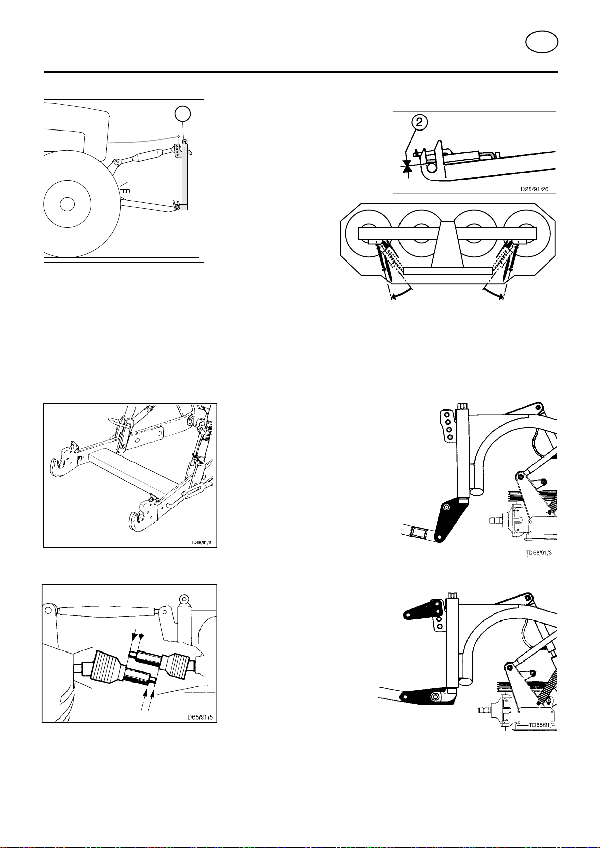
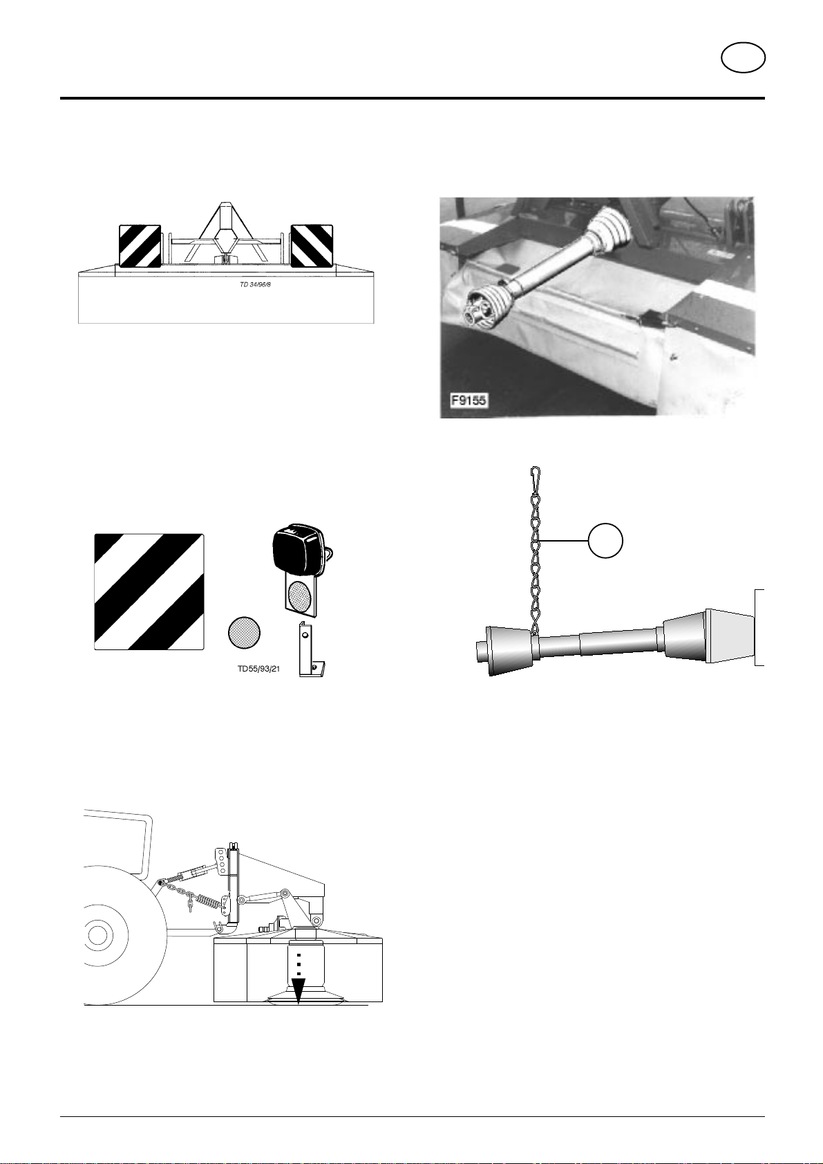
Snap Connector (1).......................................................................................................................... 4
Attaching problems .......................................................................................................................... 4
Connecting to tractor........................................................................................................................ 5
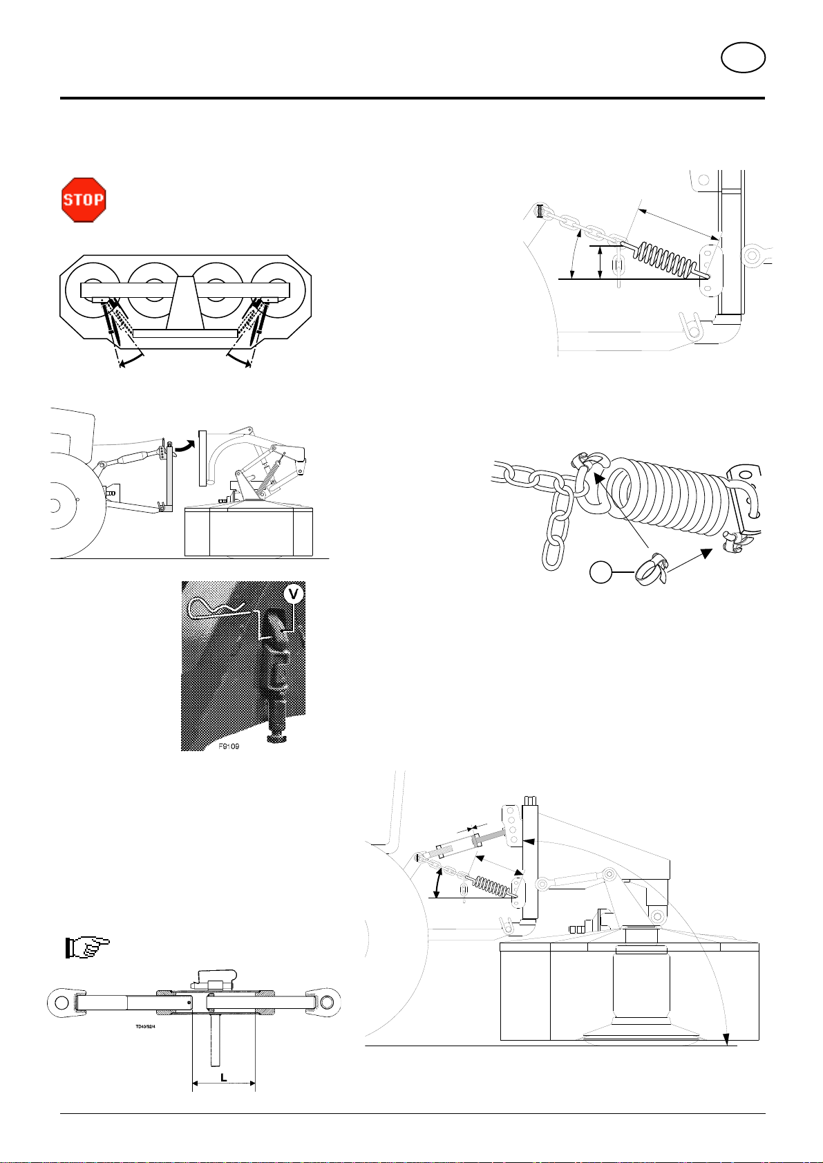
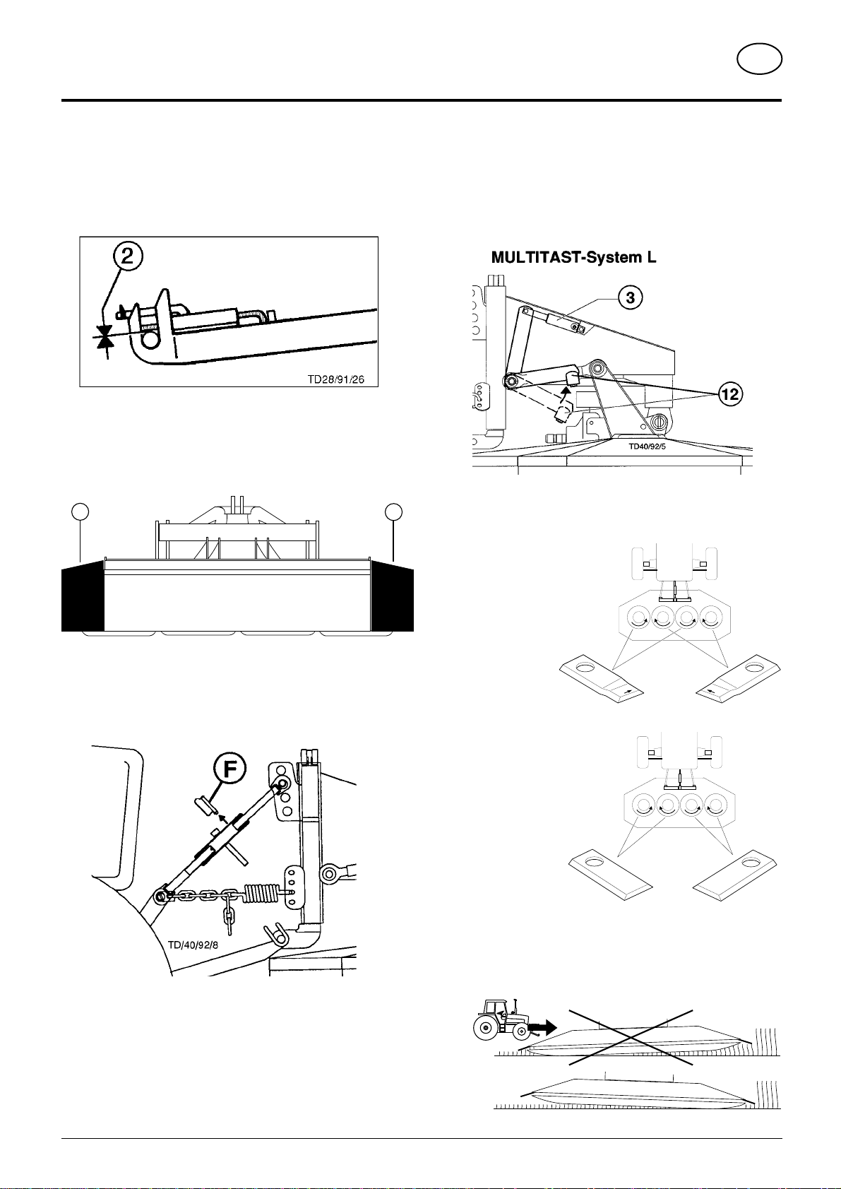
Adjusting(8i the MULTITAST-System L ............................................................................................ 5
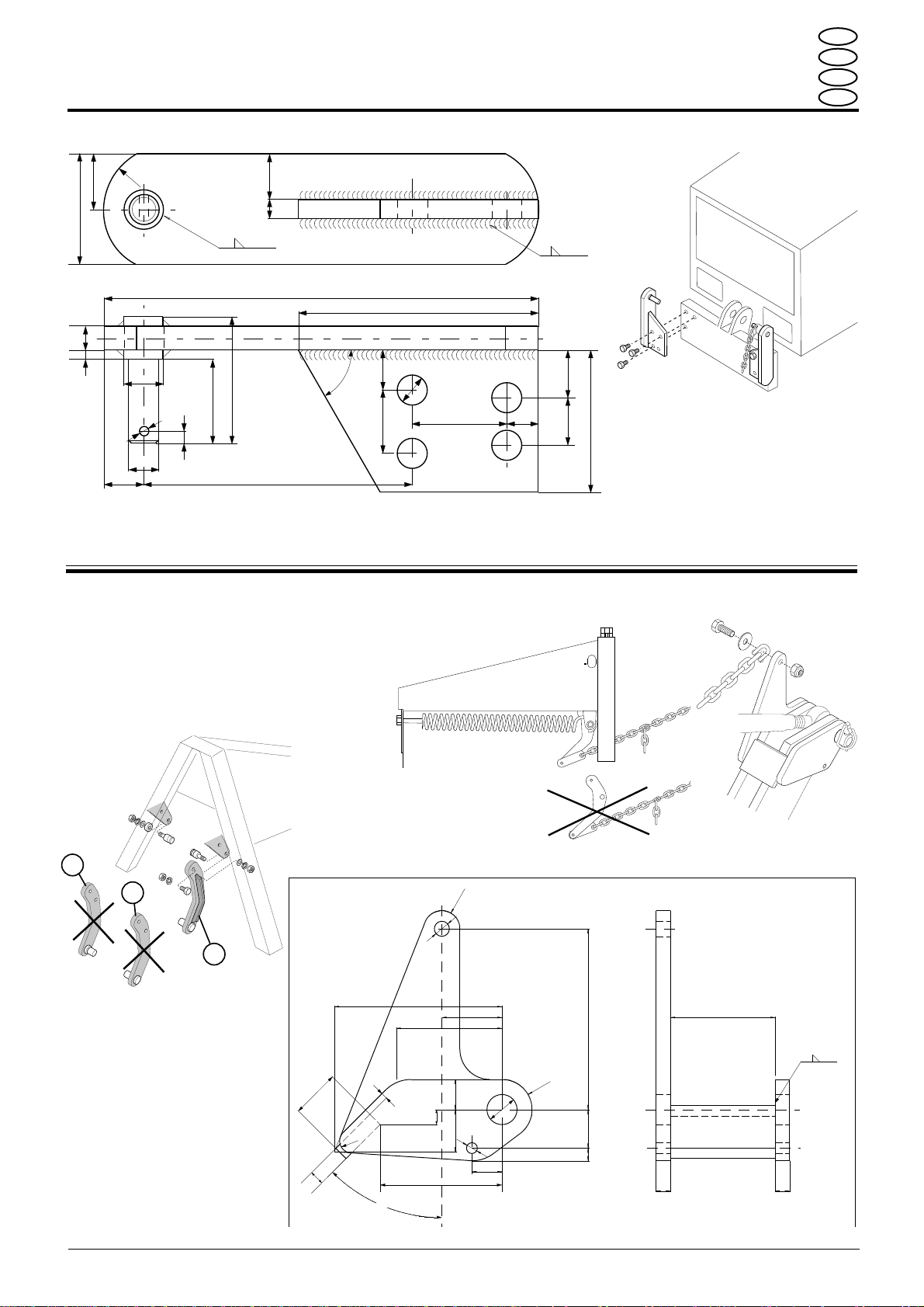
Spring tensioning ............................................................................................................................. 5
Adjusting the upper link.................................................................................................................... 5
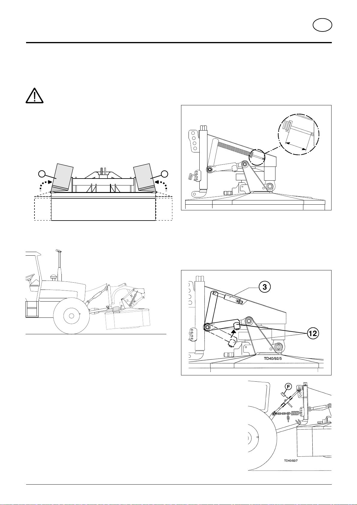
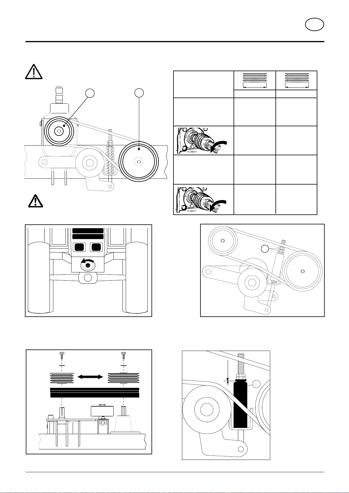
Adjustment of the damped steering mechanism (DSM) .................................................................. 3
Function of the damped steering mechanism .................................................................................. 3
Problems which may arise during operation and their correction .................................................... 3
Mowing............................................................................................................................................. 9
Hints ................................................................................................................................................. 9
Double cut ........................................................................................................................................ 9
Swath makers (CAT 270 plus front Masch.Nr.: .. . - 03690) ....................................................... 12
Swath makers (CAT 310 plus front Masch.Nr.: .. . - 01390) ....................................................... 12
Swath makers (CAT 270 plus front Masch.Nr.: .. . + 03691) ...................................................... 13
Swath makers (CAT 310 plus front Masch.Nr.: .. . + 01391) ...................................................... 13
Maintenance................................................................................................................................... 15
Safety points .................................................................................................................................. 15
Pay attention to correct assembly! ................................................................................................. 15
Changing the cutters ...................................................................................................................... 15
Checking the mowing blade suspension ........................................................................................ 15
Mower disc ..................................................................................................................................... 15
Winter storage................................................................................................................................ 15
Lubrication chart ............................................................................................................................ 15
Shorten upper link............................................................................................................................ 1

342 / ANBAU / 9700-GB
Connecting unit to tractor GB
- 4 -
Snap Connector (1)
Safety hints:
see supplement-A1 points 8a. - 8h.)
- Mount snap connector (Weiste triangle)
onto the front loader in a vertical position
or inclined slightly forward.
- Locklowerlinkpin(2)freeof
play.
Before connecting or
disconnecting
- bringbothswath discs tothe
most outward position (A).
Attaching problems
On lifting gear with a crosspiece bet-
weenthelowerlinks,damagecouldoccur
to the drive shaft when lowering the
attached implement. In order to prevent
damage an extra elevator unit is to be
installedbetweentheWeiste-triangleand
the lifting gear (see spare parts list for
accessory part).
When towing implements whose p.t.o
stub is positioned a long way forward,
thedriveshaftmustbeshortenedquitea
bit. When the implement is engaged
thentereisinsufficientcasingtooverthe
drive shaft.
Inthis case anaccessory kit isnecessa-
ry which positions the implement ap-
prox.200 mmforwards (seespare parts
list for accessory part).
TD28/91/28
1
495.672
AA

342 / ANKUPPELN / 9700-GB
- 5 -
GB
Connecting unit to tractor
TD28/91/8
Connecting to tractor(8a - 8e
Before connecting or
disconnecting
- bring both swath discs to the most
outward position (A).
- Connect mower
unit.
- Secure locking
clamp (V) with cot-
ter pin.
Adjusting(8i the MULTITAST-
System L
- Thetelescopicupperlinkenablesthemowing
drums to adapt to uneven ground that runs
diagonally to the direction of drive.
- The area of swing (L) can be adjusted by
turning the spindle.
Shorten upper link (see Supple-
ment D)
(8a - 8e, 8i see Supplement A1
Spring tensioning
Theforceappliedonthegroundbythemowing
drums is controlled by spring tension.
1.Lift unit hydraulically.
2.Hook up main spring.
3.Lower unit to the ground.
CAT 310
front
: The
adjusting measurement
should be 425 mm.
4.The optimum angle of "20°- 22°"
shouldbemaintainedaswell. This
can be checked by using the
measurement "150 mm".
• Variousattachmentsforthedifferenttractortypesareshownonthefollowing
pages. These atachments are manufactured for relatively simple self-
assembly.
5. Slip the hose clamp (20) onto the tension spring.
Doing this means that
springtensiondoesnot
have to be checked
every time unit is
attached to tractor.
The set measurement
of"425mm"needonly
be checked and, if
necessary, adjusted
when tractors are
changed.
TD38/94/5
20 - 22°
150 mm
425 mm
TD29/93/2
20
425
mm
TD38/94/2b
20 - 22°
A
0 mm
90°
Adjusting the upper link
1. Lower unit to the ground.
2. Vertically allign attachment frame (90°).
3. Adjust distance (A = 0 mm).
The mower unit must not tip forward during operation.
495.672
AA

- 6.3-
9501 ANBAUTEILE (333)
ANBAUTEILE
PIÈCES D'ADAPTATIONS SPÉCIALES
SPECIAL ATTACHING KITS
SPECIALE AANBOUWDELEN
D
F
GB
NL
480 (2x) 4150 (2x)
FENDT 304
TD40/94/11
ANBAUKONSOLE
Variante - 2
40
25
20
R 40
12 29
60
°
150
19
60
30 30
90
6
ø19
ø25
6
8
53
80
15
25
275
35
70
170
TD40/94/4
Anbau CAT NOVA 260
front
an den MB-TRAC 1000
• Es wird nur eine Kette verwendet.
• AmMähwerkistderlinkeHebel (H)unddie Kettezu
entfernen.
• Den rechten Hebel (H1) entfernen und den
verstärkten Hebel (H2) montieren.
TD45/94/27
Hebel links
entfernen
H
H1
H2
TD8/95/5
TD8/95/1
4 75 (2*)
R 10
25
35
140
101
25
5
12,5
12
40
MB-TRAC 1000
1 STK. ANBAUKONSOLE
150
(88)
25.5
1212
87+1
12,5
9
10 32
R 15
50
R 25
45°
TD8/95/2

- 6.4-
9501 ANBAUTEILE (333)
ANBAUTEILE
PIÈCES D'ADAPTATIONS SPÉCIALES
SPECIAL ATTACHING KITS
SPECIALE AANBOUWDELEN
D
F
GB
NL
DEUTZ
AGRO-XTRA
ø19
216
55
45
82
+1
-0
TD40/94/9
ANBAUKONSOLE
30
5 x 45°17
25,5
25,5
230
10099
35
70 / 10
Material: ST 50-2K
TD40/94/12
Massey Ferguson
2 Stk. ANBAUBOLZEN für MF 3065
45°
ø19
ø25
6
6
36
2
8
53
193
TD40/94/5

GBDAMPED STEERING MECHANISM
(optional equipment)
- 5.3 -
9500-GB FOL (342)
5. Remove mounting bracket and
fit in position "B".
• Securemounting bracket with
spring clip (F).
6. Lower hydraulically (FL).
7. Check
• Raise mechanism laterally, approx. 50 kg
• Raise mechanism at front, tipping towards the rear must be
easily possible.
Problems which may arise during
operation and their correction
TD10/95/8
B
F
TD40/94/7
Adjustment of the damped steering
mechanism (DSM)
1. Fit the mechanism to the towing vehicle (see pages 4, 5).
2. Carry out adjustment of the damped steering mechanism on an a
level surface (FL).
• Unhook both balance springs.
• Thebracketmustbesetinposition
"A".
• Adjust length (L) by rotating the
spindle.
• Set the damped steering
mechanism at the towing vehicle
and the quick-release coupling (Weiste triangle).
3. Raise the mechanism hydraulically (H1).
4. Fit balance springs.
• The set distance should be 42 cm (see above).
TD40/94/6
42 cm
( L )
FL
TD10/95/7
A
F
TD10/95/10
H1
Functionofthedampedsteeringmechanism
• The damped steering should be used when
operating on uneven terrain.
The advantages:
- the mower unit adapts especially well to suit the
terrain
- better mowing performance
- less loading and wear and tear on moving parts
Problem
• The mower unit digs into
the ground, the springing
on the DSM is too weak.
• Double cut, the springing
on the DSM is too strong.
Remedy
- Attachtoholehigherupthe
Weiste triangle.
- Readjustthelength(L)(see
Points 2 - 7).
- AttachDSMtoaholedown
the Weiste triangle.
- Readjustthelength(L)(see
Points 2 - 7).
TD10/95/11
TD10/95/11a
TD10/95/12
TD10/95/12

- 6.1-
342 / TRANSPORT / 9600-GB
Transport position GB
Changing from working position to
transport position
Safety Precaution!
see supplement-A1 points 7.), 8c. - 8h.)
Changingfromworkingpositiontotransportposition
is only to be carried out on even, firm ground.
Neverletthemowingmechanismrunwiththemower
raised.
1. Wait for drums to stop turning.
2. Side guard plates (10 and 11) can be folded up to reduce
transport width.
3. Lift unit hydraulically.
Securing the MULTITAST-System L for
transportation
Mechanical stabilization:
Preventsthemowingunitfromswingingduringtransportation.
- Pay attention to setting measurement "50 mm".
Hydraulical stabilization:
- The flaps (12) are swung up as far as possible by using the
hydrauliccylinders(3).Indoingthat,themowingunitisunable
to swing during transportation.
Telescopic upper link
- Bysecuringthetelescopic
upper link with the spring
cotter pin (F), jolting of
the unit can be avoided
during transportation on
uneven ground.
TD 1/93/1
50 mm
10 11
TD 60/94/4
TD28/91/10

- 6.2-
342 / TRANSPORT / 9600-GB
Transport position GB
Road Transport
• Observe the regulations issued by your country's legislative
body.
• Travelling on public roads may only be undertaken as is
described in the chapter "Transporting Position".
• Fastenlowerhydrauliclinksothatimplementcannotswingout
sideways.
Lighting during use on roads
If desired, a lighting unit can be supplied.
For single parts see spare parts list.
Parking the machine
- Before you leave the tractor, lower the machine on to
ground!
Parking the machine
• Details see chapter "Parking the machine"
- When the implement ist parked, either remove the driveshaft
and store it, or secure it with a chain.
Do not use retaining chain (H) for this.
H
TD58/94/6
TD61/94/3

342 / ABSTIMMEN DES GERÄTES / 9500 GB
Tuning the unit to the p.t.o. RPM GB
- 8 -
Loosenbothhexagonalnuts(1)whichslackensthe V-
belts.
Pay attention to correct p.t.o. direction of rotation!
TD 28/91/19
Change V-belt pulleys.
To tension pulleys
correctly, the gap
between spring
indicator (2) and
pulley is “0 mm”.
Ifgapisgreaterthen
the tension on the
spring must be
increased.
Depending on the p.t.o. RPM the V-belt pulleys (A, B) are to be set up according to the table.
Safety hints:
see supplement-A1 points 1.) 3.) 8i.)
Changing the V-belt pulleys
750 U/min
A
Ø (mm)
B
1000 U/min
227 181
206 206
Ø (mm)
It is essential to ensure that the belt pulleys are
mounted according to the chart.
1
TD 10/94/5
0 mm
2
TD 10/94/6
TD 10/94/4
AB

342 / EINSATZ 9401 GB
Field operation GB
- 9 -
Mowing
- Mowing drums in horizontal position.
- Lock lower link pin (2) free of play.
- Side guard plates (10 and 11) folded down.
- Remove spring cotter pin (F) from upper link.
10 11
TD 39/91/2
- Briefly switch hydraulic control unit (ST) to "lower" to activate
the lifting cylinder (3).
In doing that, the catch (12) is released and the unit can adapt
itself to the uneven ground.
Hints
Withveryshortgrass,thefanning
action of the set mowing blades
can be so strong that the forage
is ejected from the sides.
Solution:
Use flat mowing blades
(Nr. 434.991).
Double cut
If the mowed stalks show a double cut, then correct the tilt of the
mowing drums.
TD39/91/3
R
L
TD28/91/21
TD40/94/14

9700-GB SCHWADFORMER (333)
Field operation GB
- 12 - (8i see Supplement-A
6
TD 20/92/9
Adjustment of both swath makers(8i
Leading swath disc
Distance between mowing plate and swath disc "10-15 mm ".
- Loosen nuts on the bracket (7) and adjust bracket.
- Re-tighten nuts afterwards.
Rear swath disc
Adjustment "-10 mm".
- Loosen nuts on bar bracket (8), adjust bar bracket and then re-tighten nuts.
Adjustment of swath width(8i
The swath width can be altered by changing the position of the levers (6).
If an obstruction appears then the swath width is to be increased.
Swath makers (CAT 270
plus front
Masch.Nr.: . . . - 03690)
Swath makers (CAT 310
plus front
Masch.Nr.: . . . - 01390)

9700-GB SCHWADFORMER (333)
Field operation GB
- 13 - (8i see Supplement-A
TD 13-97-5
6
TD 13-97-4
10 - 15 mm
10 mm
-10 mm
Adjustment of both swath makers(8i
Leading swath disc
Distance between mowing plate and swath disc "10-15 mm ".
Rear swath disc
Adjustment "-10 mm".
Adjustment of swath width(8i
The swath width can be altered by changing the position of the
levers (6).
Ifanobstructionappearsthentheswathwidth is to be increased.
Swath makers (CAT 270
plus front
Masch.Nr.: . . . + 03691)
Swath makers (CAT 310
plus front
Masch.Nr.: . . . + 01391)

333 / WARTUNG / 9400GB
Maintenance GB
- 15 -
R
L
TD28/91/21
(II)
ÖL
(IV)
FETT
Safety points
• Turnengine offwhen adjustment, serviceand repairwork is
to be done.
• Do not work under the machine without safe support.
• Retighten all screws after the first hours of operation.
Cutters
The cutters on a cutting drum should be evenly
worn out, (danger of imbalance) otherwise they
are to be replaced by new ones.
Pay attention to correct assembly!
- Cutters with the
notation “L” are only to
be mounted on the left
rotatingmowing drum.
- Cutters with the
notation“R”are only to
bemountedontheright
rotating mowing drum.
Changing the cutters
- Propupthelever(29)ontheloweredgeofthedrumandpush
themoveableholder(30)downwards.Thecutter(14)ishung
onthebolt(31).Changethecuttersandcleanallforageaway
that the cutter held
from around the bolt.
Perhaps the inner
sideofthedrumalso.
Remove the lever
(29) and check if the
cutterholderbolt(31)
has returned to its
original position and
ifthecuttercanmove
freely on the bolt.
- When the bolt (31) is
greatly worn, the
holder(30)shouldbe
replaced.
Checking the mowing blade suspension
- Check immediately after driving over a hard obstacle.
- Normal check every 100 hours.
- Check more often when mowing on
rocky terrain.
Mower disc
Withmowerdiscsthatareworninthemowingbladearea,
you must proceed as follows:
- Remove lower support disc.
- Remove cutter holder nuts.
- Shift cutter holder around 1 hole (60o).
- Tighten screws firmly (120Nm) and re-check after a few
hours of operation.
- Re-mount mowing blades.
Winter storage
- Lubricate and oil the machine according to the lubrication
chart.
- Driving belts should be slackened throughout the winter.
Maintenance

- 15 -
SCHMIERPLAN (342)
F
Schmierplan
Plan de graissage
Lubrication chart
8
h
FETT
9400 Schmierplan (342)
alle 20 Betriebsstunden
toutes les 20 heures de service
after every 20 hours operation
elke 20 uren
III
1 x jährlich
1 fois par an
once a year
1 x per jaar
III
0,5 Liter 13 Liter
alle 80 Betriebsstunden
toutes les 80 heures de service
after every 80 hours operation
elke 80 uren
Oil level 2,5 - 3,5 cm
Ölstand 2,5 - 3,5 cm
Niveau d' huile 2,5 - 3,5 cm
(IV)
FETT
(II)
ÖL
D
GB

- D1-
9600 KÜRZEN OBERLENKER (333)
ANHANG - D
ANNEXE - D
SUPPLEMENT - D
AANHANGSEL - D
D F GB NL
Oberlenker kürzen
1. GerätandieUnterlenkerdes
Hubwerks ankuppeln.
2. Anbaubock senkrecht aus-
richten (90°).
3. Gewindespindel ausbauen
- Spannhülse enfernen
- Gewindespindel heraus-
drehen
4. Abstand "A1" abmessen
5. Gewindespindel kürzen
(Maß "A2" der Tabelle
entnehmen)
6. Gewindespindel einbauen
- Mit Spannhülse sichern
100 mm
170 mm
A2
A2
TD10/96/1a
90°
A1
A1 A2
510 - 590 mm 170 mm
590 - 660 mm 100 mm
660 - 760 mm 0 mm
Shorten upper link
1. Connect the unit to the lower
link of the lifting gear.
2. Vertically allign attachment
frame (90°).
3. Remove threaded spindle
- remove clamping sleeve
- unscrew threaded spindle
4. Measure gap "A1"
5. Shorten threaded spindle
(take measurement "A2"
from table)
6. Screw in threaded spindle
- secure with clamping
sleeve.
Topstang korter
afstellen
1. Machine aan de hefarmen
van de hefinrichting
koppelen.
2. Aanbouwbok loodrecht
instellen (90°).
3. Draadstang demonteren
- spanhuls verwijderen
- draadstang uitdraaien
4. Afstand "A1" opmeten
5. Draadstangoplengtemaken
(maat "A2" van de tabel
aanhouden)
6. Draadstang weer monteren
- met spanhuls borgen.
Raccourcir le 3 ème
point
1. Atteler la machine aux bras
inférieurs du relevage.
2. Positionnerlebâtid'attelage
à la verticale.
3. Démonter l'embout fileté.
- Enlever la goupille
mécanindus.
- Dévisser l'embout fileté.
4. Mesurer la cote "A1"
5. Raccourcir l'embout fileté.
(Prendre la mesure "A2"
dans le tableau).
6. Remonter l'embout fileté.
- Le fixer avec la goupille
mécanindus.
Table of contents
Popular Industrial Equipment manuals by other brands

Spraying Systems
Spraying Systems AutoJet AccuCoat HD15 owner's manual

Tolomatic
Tolomatic BC4 Series quick start guide

aquamundus
aquamundus GreaseShield 1000 AST-PF installation guide

woodmizer
woodmizer MP180 user manual

Powerplus
Powerplus POWX902 manual

Delta
Delta WHITEWATER DF Series Installation, operation and maintenance manual