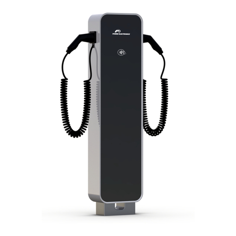
Power Electronics NB WALL Series User manual

NB WALL
HARDWARE AND
INSTALLATION MANUAL
ELECTRICAL VEHICLES CHARGING SOLUTIONS


NB Wall
EV CHARGING SOLUTIONS
Hardware and Installation Manual
Edition: April 2020
NBWHW01BI Rev. B

NB Wall
POWER ELECTRONICS
2
ABOUT THIS MANUAL
ABOUT THIS MANUAL
PURPOSE
This manual contains important instructions for the installation, configuration and use of NB Wall electric
vehicle chargers. From now on, this manual refers to NB Wall with the term "charger" or “equipment”.
Power Electronics reserves the right to modify product features.
TARGET AUDIENCE
This manual is intended for qualified customers who will install, configure and operate NB Wall electric
vehicle chargers.
Only qualified technical personnel validated by Power Electronics may install and start up the chargers.
REFERENCE MANUALS
The following reference documents are available for electric vehicles chargers:
•User manual
POWER ELECTRONICS CONTACT INFORMATION
Power Electronics USA Inc.
1510 N. Hobson Street, Gilbert,
Phoenix
AZ 85233
UNITED STATES OF AMERICA
US Sales: 602-354-4890 / (480) 519-5977
Fax: (415) 874-3001
Power Electronics España, S.L.
Polígono Industrial Carrases
Ronda del Camp d’Aviació nº 4
46160, Llíria (Valencia)
SPAIN
Tel: (+34) 961 366 557 / Fax: (+34) 961 318 201
Website: www.power-electronics.com

POWER ELECTRONICS
NB Wall
REVISIONS
3
EN
REVISIONS CONTROL
DATE
REVISION
DESCRIPTION
19 / 12 / 2019
A
First edition
09 / 04 / 2020
B
US references included.
About. Safety symbols. Safety instructions. Introduction. Technical
characteristics. Handling and transportation. Preparation for installing
the equipment. Cable access and connections. Protections. Interface.
Communications. Commissioning. Safe stop. Maintenance. Declaration
of conformity CE.
The equipment and technical documentation are periodically updated. Power Electronics reserves the right to modify all or part of the
contents of this manual without previous notice. To consult the most updated information on this product, you may access our website
www.power-electronics.com, where the latest version of this manual can be downloaded. The reproduction or distribution of the present
manual is strictly forbidden unless express authorization from Power Electronics.

NB Wall
POWER ELECTRONICS
4
TABLE OF CONTENTS
TABLE OF CONTENTS
ABOUT THIS MANUAL ...............................................................................................................................2
SAFETY SYMBOLS.....................................................................................................................................6
SAFETY INSTRUCTIONS............................................................................................................................7
TORQUE AND SCREW SIZING.................................................................................................................12
INTRODUCTION...................................................................................................................................13
General description of the equipment.................................................................................................13
Charging process ...............................................................................................................................15
Advanced charge functionalities.........................................................................................................15
Descriptive label.................................................................................................................................16
Regulatory framework ........................................................................................................................16
TECHNICAL CHARACTERISTICS ......................................................................................................17
DIMENSIONS AND WEIGHT................................................................................................................19
HANDLING AND TRANSPORTATION ................................................................................................21
Reception...........................................................................................................................................21
Storage...............................................................................................................................................21
Unpackaging ......................................................................................................................................21
Handling and transportation ...............................................................................................................22
PREPARATION FOR INSTALLING THE EQUIPMENT.......................................................................23
Site recommendations........................................................................................................................23
Minimum safety distances..................................................................................................................24
Maximum hose range.........................................................................................................................24
Anchoring of the equipment................................................................................................................25
Ventilation system ..............................................................................................................................27
Charging current adjustment..............................................................................................................28
CABLE ACCESS AND CONNECTIONS..............................................................................................29
Input wiring.........................................................................................................................................29
Access................................................................................................................................................30
Connections .......................................................................................................................................33
PROTECTIONS ....................................................................................................................................38
Overcurrent and short circuit protection..............................................................................................38
Residual current monitoring (RCM)....................................................................................................38
Charge circuit interrupting device (CCID)...........................................................................................38
INTERFACE..........................................................................................................................................39
Controls..............................................................................................................................................39
Indicators............................................................................................................................................39

POWER ELECTRONICS
NB Wall
TABLE OF CONTENTS
5
EN
COMMUNICATIONS.............................................................................................................................40
Wi-Fi communication..........................................................................................................................40
Ethernet connection............................................................................................................................40
Bluetooth connection..........................................................................................................................40
3G / 4G communications....................................................................................................................41
COMMISSIONING ................................................................................................................................42
SAFE STOP..........................................................................................................................................44
MAINTENANCE....................................................................................................................................45
Status.................................................................................................................................................45
Checklist.............................................................................................................................................46
Power Test (status 1) .........................................................................................................................47
Dead Test (status 2)...........................................................................................................................48
DECLARATION OF CONFORMITY CE.....................................................................................................49

NB Wall
POWER ELECTRONICS
6
SAFETY SYMBOLS
SAFETY SYMBOLS
Always follow safety instructions to prevent accidents and potential hazards from occurring.
In this manual, safety messages are classified as follows:
Other symbols used in this manual for safety messages are the following:
NOTICE
Definition of acronyms used in this document:
•EV: Electrical vehicle
•AC: Alternating current
•DC: Direct current
•PPE: Personal Protection Equipment
•RFID: Radiofrequency identification
•MCB: Miniature circuit breaker
•RCD: Residual current device
•RCM: Residual current monitor
•MID: Measuring instrument directive
•CCID: Charge circuit interrupting device
WARNING
Identifies potentially hazardous situations where dangerous voltage may be
present, which if not avoided, could result in minor personal injury, serious
injury or death.
Be extremely careful and follow the instructions to avoid the risk of electrical
shocks.
CAUTION
Identifies potentially hazardous situations, which if not avoided, could result
in product damage, or minor or moderate personal injury.
Read the message and follow the instructions carefully.
NOTICE
Identifies important measures to take in order to prevent damage equipment
and warranty lost, as well as encouraging good use and environmental
practices.
Hot surface. Be careful and follow the instructions to avoid burns and personal injuries.
Risk of fire. Be careful and follow the instructions to prevent causing an unintentional fire.
Caution, risk of electric shock. Energy storage timed discharge. Wait for the indicated
time to avoid electrical hazards.

POWER ELECTRONICS
NB Wall
SAFETY INSTRUCTIONS
7
EN
SAFETY INSTRUCTIONS
IMPORTANT!
Read carefully all documentation before handling the equipment and pay special attention to safety
recommendations to maximize the performance of this product and ensure its safe use and installation.
The installer must follow the instructions provided in this manual, as well as the good electrical practices
and identify all warnings and recommendations before starting up and operating the electric vehicles
charger.
WARNING
FIRST CONSIDERATIONS
The operations detailed in this manual can only be performed by qualified personnel.
The condition of qualified personnel referred to in this manual shall be at least the condition that meets
the standards, regulations and safety laws applied to the installation and operation of this equipment.
Read and retain the Installation Manual for future reference.
Before assembling the charger, read all instructions, caution signs and other sections of this manual.
Failure to follow these warnings can result in severe electrical shock or death. Pay attention at all times
to prevent possible accidents.
Make sure that all safety regulations in force at the place where the charger is installed regarding
both Medium Voltage and Low Voltage operations are complied with. Otherwise, you may get an
electric shock.
The electric vehicle charging system may cause an ELECTRICAL DISCHARGE if the warnings
indicated in this manual are not followed.
Make sure the charger is completely disconnected from the power supply and grounded before
handling or servicing. Otherwise, there is a risk of electric shock. To avoid electrical hazards,
disconnect the input supply, ground the equipment, remove control voltages before performing any tasks,
and ensure that busbars are completely discharged. Warning and safety labels must be properly affixed
to terminals, cabinets and control panels in accordance with local regulations.
When working on electrical installations, always remember to apply the FIVE GOLDEN RULES:
1. Visible shutdown of all live sources.
2. Mechanical locking of all cutting elements.
3. Verify the absence of voltage by using the appropriate tools for the voltage of the installation.
4. Ground and short-circuit all possible voltage sources.
5. Delimit and mark the work area.
Do not modify the equipment. If you fail to do so, Power Electronics will not assume any liability, and
the product warranty will be voided.

NB Wall
POWER ELECTRONICS
8
SAFETY INSTRUCTIONS
WARNING
The housing must be properly closed, otherwise it may not adequately protect people or
property from any abnormal situation inside the equipment.
The output airflow can reach high temperatures that could harm people exposed to it.
Electric shock danger. The steps to isolate the equipment must be carefully followed before performing
any task or opening any cover of the equipment. Avoid inappropriate actions that may cause electric
shock.
Always wear the appropriate personal protective equipment (PPE) for each task. and work in
electrical areas with dry hands. Otherwise, you may get an electric shock.
Do not subject cables to abrasion, excessive stress, heavy loads or pinching. Otherwise, you may
get an electric shock.
Do not supply power to a damaged charger or charger with missing parts, even if the installation
is complete. Otherwise, you may get an electric shock.
In the event that the charger stops due to a loss of power, do not do any work on it. The auto-restart
function may be enabled and you may receive an electric shock.
During any maintenance task on the equipment, please make sure that there will be no
electric vehicle connected charging.
USE
Do not use this equipment for purposes other than the electric vehicle charging with the modes
provided for this product and defined in this manual.
Do not disconnect or connect any terminals while the equipment is running. Otherwise, you may
get an electric shock and the equipment may be damaged.
Do not use this product if its enclosure or electric vehicle connector(s) (on both the charger and
vehicle sides) or insulation cable are broken, cracked or otherwise damaged. Otherwise, you may
get an electric shock
CONNECTION TO EARTH
Prevention of electric shock:
•The charger chassis must be properly grounded to prevent a possible electrical shock if a leakage
current flows through the enclosure. Disconnect all power supplies before proceeding with
maintenance operations inside the equipment.
•Only connect the grounding device to the charger's grounding plate. Do not use the enclosure or
chassis screws for grounding.
The protective earth wire must be connected first and last disconnected

POWER ELECTRONICS
NB Wall
SAFETY INSTRUCTIONS
9
EN
CAUTION
Install the equipment, both the power station and the recharging poles, on a solid, level surface in
a location where there is no risk of explosion, flooding, or impact damage. Follow the
recommendations on how to build the foundation of this manual. Otherwise, there is a risk of
malfunction and even permanent damage.
Never clean the surfaces or interior of the charger with abrasive liquids, solvents or cleaning
agents that could damage it. Nor should water be applied with excessive pressure.
Disconnect the input power in case the equipment gets damaged.
Otherwise, it could result in a secondary accident or a fire.
Do not allow lint, paper, wood chips, dust, metallic chips or other foreign matter into
the equipment. Otherwise, a fire or an accident could occur.
After the input power is applied or removed, the equipment will remain hot for a few
minutes. Touching internal hot parts could result in skin burns
IMPORTANT RECOMMENDATIONS FOR CHARGING ELECTRIC VEHICLES:
CAUTION
Follow at all times the charging process described by the electric vehicle manufacturer.
This device should be monitored when used near children.
Do not handle the vehicle or charger during the loading process (washing of the vehicle,
intervention in the vehicle engine compartment, handling of the loading post, etc.).
Do not modify or interfere with the electrical installation while charging the vehicle.
Failure to do so could result in electric shock.
Do not charge the vehicle in the event of water, signs of corrosion or foreign matter on the charger
cable connector or vehicle charging socket. Otherwise, there is a risk of fire and electric shock.
Do not attempt to touch the terminals of the charging station connector cable or the vehicle
charger socket, nor insert objects into them. Failure to do so could result in electric shock.
Do not attempt to disassemble, repair, alter or modify the charging connector or any part of the
charger. The connector is not a user serviceable device. Contact Power Electronics.
Always be careful with the charger's cable and connector: treat it carefully, do not crush it,
immerse it in water, pull it out, or hit it, etc.
Follow the directions given by the vehicle manufacturer regarding the suitability of charging the
vehicle when you or the vehicle are exposed to intense rain, heavy electrical storm or other severe
weather.

NB Wall
POWER ELECTRONICS
10
SAFETY INSTRUCTIONS
PERSONAL PROTECTIVE EQUIPMENT (PPE from now on) REQUIRED
The use of PPE in accordance with standards is required to repair and maintain the equipment. Follow
applicable instructions at the installation site to comply with national and local regulations.
In the case of tasks with voltage present, it is mandatory to use an Electric Arc Safety Kit, anti-static
and flame-retardant clothing, insulating gloves and helmet with a screen.
A detailed example of the PPE used is shown below. The customer must specify in his safety
instructions (hazard statement and work procedure) which PPE is required and when and how they
should be used according to his electric arc studies, the characteristics of the site, the chargers, the
installation and the country.
Power Electronics assumes no liability for damage resulting from improper use of the equipment
or failure to comply with local or national regulations.
Always follow local regulations / Health & Safety standards.
PPE FOR INSTALLATION
Mechanical gloves
Safety boots
Safety helmet
Safety glasses
Additional PPE for commissioning and maintenance tasks
PPE
STANDARD REGULATION
Safety footwear:
EN ISO 20345
Helmet with screen:
UNE-EN 397, UNE-EN 166
Safety clothes for electrical works:
EN 470-1, EN 61482-1-2, EN 1149-5, EN 11612
Electric gloves:
EN 60903:2003

POWER ELECTRONICS
NB Wall
SAFETY INSTRUCTIONS
11
EN
NOTICE
RECEPTION
•Electric vehicle chargers are supplied after passing strict performance tests and are carefully
packed for shipment.
•In case of damage to the unit during transportation, notify the shipping agency and Power
Electronics (International +34 96 136 136 65 57, USA + 1-415-874-3668) or your nearest agent
within 24 hours of receipt of the merchandise.
RECYCLING
Packaging equipment must be recycled. Separate all different materials (plastic, paper, cardboard, wood…)
and place them in the corresponding containers. Ensure waste collection is properly managed with a Non-
Hazardous Waste Agent.
To guarantee health and natural environmental sources protection, the European Union has
adopted the WEEE directive concerning discarded electric and electronic equipment (SEEA).
Waste of electrical and electronic equipment (WEEE) must be collected selectively for
proper environmental management.
Our products contain electronic cards, capacitors and other electronic devices that should be
separated when they are no longer functional. These WEEEs should be managed accordingly
with a Hazardous Waste Agent.
Power Electronics promotes good environmental practices and recommends that all its products
sold outside of the European Union, once they reach the end of their life, are separated and the
WEEE managed according to the particular country applicable legislation (especially: electronic
cards, capacitors and other electronic devices).
If you have any questions about the electric and electronic equipment waste, please contact Power
Electronics.
CYBERSECURITY DISCLAIMER
This product is designed to be connected to and to communicate information and data via a network
interface. Access to the system is restricted to those employees who legitimately need it for reasons of
maintenance and/or updating of the system.
It is the customer´s sole responsibility for providing and continuously ensuring a secure connection between
the product and customer network or any other network (as the case may be). Customer shall establish and
maintain any appropriate measures (such as but not limited to the installation of firewalls, application of
authentication measures, encryption of data, installation of antivirus programs, etc.) to protect the product,
the network, its system and the interface against any kind of security breaches, unauthorized access,
interference, intrusion, leakage and/or theft of data or information.
Power Electronics and its affiliates are not liable for damages and/or losses related to such security
breaches, any unauthorized access, interference, intrusion, leakage and/or theft of data or
information.

NB Wall
POWER ELECTRONICS
12
TORQUE AND SCREW SIZING
The following table shows, broadly speaking, the recommended torque for both mechanical and electrical
connections, applicable to all cabinets.
SCREW SIZE
RECOMMENDED TORQUE
METRIC
(mm)
ENGLISH
(inches)
DIN (Nm)
ASTM (ft*lb)
6,9 QUALITY[A]
8,8 QUALITY[A]
A449 TYPE 1[A]
A325 TYPE 1[A]
M3
1/8
1
1,3
-
-
M4
5/32
2,5
3
M5
3/16
4
6
M6
1/4
5
10
4
M8
5/16
20
25
9
M10
7/16
40
50
25
M12
1/2
60
70
38
50 –58
M14
9/16
100
120
54
-
M16
5/8
150
210
75
99 –120
[a] For other qualities, follow the screw’s manufacturer guidelines.
CAUTION
For all screwing that holds a particular component such as a bus, contactor, etc. it will be necessary to
apply the tightening torque indicated by the manufacturer of the same component
Screwing should be tightened correctly only when necessary, i.e. when the factorymarks are not in place.
For small screws that do not have marks, the good electrical praxis will determine if it is loose.

POWER ELECTRONICS
NB Wall
INTRODUCTION
13
EN
INTRODUCTION
NB Wall is a robust and attractive outdoor AC Charging system, making it ideal for car parks and smart
homes.
Its smart design offers a simple, fast and easy charging experience, which makes NB Wall the best AC
charging solution for applications that require maximum integration with the most advanced functionalities.
It has been designed with durability, reliability and ease of use in mind. With output power of 2 x 22kW
(IEC) or 2 x 7.7kW (US), NB Wall is compatible with AC Type 1 and 2 connectors.
General description of the equipment
The NB Wall charger has two different models models that mark some of their components and
functionalities (refer to “Technical Characteristics”section). Besides, they have the possibility of adding
some extra options.
The possibility of installing each connector will depend on the application of local regulations. If only one
connector is required, the solution selected will be frame 1. On the other hand, if two connectors are
required, then the solution will be frame 2.
It does not have control buttons, as its operation consists of a simple intuitive interface. It has a
smartphone application to facilitate the interaction with the user and integrates status indicators so that
drivers can easily identify its availability.
Frame 1
Frame 2
Mode 3
AC
Power level
Connectors
AC type 1 AC type 2
US IEC
1

NB Wall
POWER ELECTRONICS
14
INTRODUCTION
The following image shows the charger overview with the main components:
Note: The representation and location of the components may vary depending on the model.
Connectors
The characteristics and parts of each type of connector are indicated below. The appearance of the
connectors may change to that shown in the following images. AC connector type 1
AC connector type 2
[1] Only applicable in IEC models as optional.
RFID reader
Charging connector
Status indicator
Charging hose
Plug-in socket [1]
Charging hose
Interlocking
system
Handle grip
Connecting
Contacts
Connecting
Contacts
Charging hose
Handle grip
Interlocking
system
Connecting
Contacts

POWER ELECTRONICS
NB Wall
INTRODUCTION
15
EN
Charging process
The following sequence presents the process to be followed by the user for use in a loading session:
1. If the user management has not yet been configured and the charger is available, connect the hose
to the vehicle to start charging automatically and go to point 4.
2. If user management has been configured and the charger is available, activate the chargingsession
from the mobile application or RFID contact.
3. If the session has been validated, connect the charger to the vehicle using the appropriate hose.
4. Make sure that the connector has been interlocked.
5. If the session and communication between the charger and the vehicle are established correctly,
the charging will start.
6. Stop charging. The charging can be stopped in different ways: because it has reached 100% and
it stops automatically, by means of the mobile application, RFID contact or by stopping the load
from the vehicle itself.
7. Once the charging has stopped, the connector can be released.
Advanced charge functionalities
Smart fleet management
This functionality has been designed to minimize the initial investment and operation costs.
It is able to balance the powerbased on the number ofcharging posts in use. Therefore, the total power
required to supply the total energy gets substantially reduced, representing a cost reduction in the
electrical facility infrastructure and a cost saving due to a minor power contracted. Besides, the
hardware and the back-office communication is optimized.
Dynamic power control
This functionality is an option, it ensures dynamic adaptation of the power being used to charge the
vehicle in accordance with the energy being consumed by other electrical circuit, without having to
increase contractual power capacity

NB Wall
POWER ELECTRONICS
16
INTRODUCTION
Dual power sharing
Thanks to the Dual Power Sharing functionality, the power is equally distributed between both outputs
(or configurable) without exceeding the current limit set for the charger.
When one of them finishes charging, the total power is available for the other one.
Descriptive label
The descriptive label of the equipment is located at the base of the charger. The following image shows
an example of the label:
Regulatory framework
The NB Wall EV charger is a device that connects to the low voltage AC network and provides an AC
supply intended for charging electric vehicles.
Its certification as a product, in accordance with current legislation in Europe, is carried out by
assessing compliance with the following standards where applicable:
•IEC 61851-1: Conductive charging system for electric vehicles. Part 1: General requirements.
•IEC 61000-6-2: Electromagnetic compatibility (EMC). Part 6-2: Generic standards - Immunity
standard for industrial environments.
•IEC 61000-6-3: Electromagnetic compatibility (EMC). Part 6-3: Generic standards - Emission
standard for residential, commercial and light-industrial environments.
Additionally, it is also in accordance with current legislation in USA, it is carried out by assessing
compliance with the following standards where applicable:
•UL2594: Standard for Electric Vehicle Supply Equipment.
•FCC part 15 - class B: unintentional radiators.
•NEC –Art 625: Electric Vehicle Charging Systems.
DESCRIPTION
1
Manufacturer Information
2
Technical features
3
Product identification
1
2
3

POWER ELECTRONICS
NB Wall
TECHNICAL CHARACTERISTICS
17
EN
TECHNICAL CHARACTERISTICS
The NB Wall charger offers the following IEC standard features. For other configurations, consult Power
Electronics.
2

NB Wall
POWER ELECTRONICS
18
TECHNICAL CHARACTERISTICS
The NB Wall charger offers the following standard features for general US configurations for other
configurations, consult Power Electronics.
This manual suits for next models
2
Table of contents
Other Power Electronics Automobile Accessories manuals
Popular Automobile Accessories manuals by other brands

BTCPower
BTCPower EVSE 200 KW Installation and user manual

DRAGONFIRE
DRAGONFIRE RacePace 01-2110 installation instructions

Fishbone Offroad
Fishbone Offroad FB23083 installation instructions

aFe Power
aFe Power 77-47001 instruction manual

Whispbar
Whispbar K046W Fitting instructions

Ullstein Concepts
Ullstein Concepts 15V 5080N Assembly instruction