manuals.online logo
Brands
  1. Home
  2. •
  3. Brands
  4. •
  5. Power Gear
  6. •
  7. Control Unit
  8. •
  9. Power Gear 909510000 User manual

Power Gear 909510000 User manual

Page 1of 4
Content
These general service notes
and the Step Test Procedures
address the most common
questions about Kwikee
electric steps. Due to the
number of variable conditions,
you may experience
symptoms other than those
covered.
*IMGL controls are on 2006 or
newer model year steps. The
service procedures outlined in
this document are for IMGL
controls only.
12 volt automotive batteries
contain sulfuric acid which
can cause severe burns. Avoid
contact with the skin, eyes,
and clothing. 12 volt
automotive batteries produce
hydrogen gas which is
explosive; keep cigarettes,
open flames, and sparks away
from the battery at all times.
NOTE
© Co
py
ri
g
ht PowerGear Issued Ma
y
, 2011 #82-ST0500, Rev. 0C 7/20/12
KWIKEE STEP TESTING PROCEDURES for CONTROL #
909510000, 1510000140, 1510000158 or any IMGL
(Integrated Motor/Gearbox/Linkage)* STEP CONTROL
If the power wire to the step is disconnected from its source and reconnected, a spark is common. This is
caused by the momentary charging of the control unit and does not necessarily indicate the system is
staying on, which would cause a drain on the battery.
To determine if a control unit is not shutting off, remove the four-way connector to the chassis and the
two-way connector between the step motor and the control unit. Place a voltmeter between the red and
yellow motor wires at the two-way connector from the control unit. Reconnect the four-way Connector.
Refer to OEM Owner’s Manual (or OEM Requirements) and place the step switch in the appropriate
position for the step to remain in the extended position. If any voltage registers on the meter for more
than 5 seconds, the control unit is not shutting off and may be defective. When doing this test, switch the
voltmeter leads back and forth between the red and yellow motor wires to be sure no voltage registers.
If any voltage registers for more than 5 seconds, disconnect the four-way connector to keep the step
motor from overheating. If zero voltage is present, the control unit has shut off and is normal.
If the step does not work or operates erratically (for example, extends part way and shuts off) the first
item to check is the vehicle battery. Low supply voltage may cause erratic operation of the step. Poor
ground connections may also cause erratic operation of the step. Check battery voltage and condition. A
battery in good condition and properly charged will have a no load voltage of approximately 12.6 volts.
Check the voltage at the battery and at the four-way connector at the control unit. Insure that all battery
and step control unit connections are clean and secure. Recharge or replace the battery as necessary
and retest the step for proper operation.
The step may also operate erratically if it is operating directly from a converter and the converter output
is not adequate or properly filtered for clean DC voltage. The converter must be capable of producing a
minimum of 30 amps for proper step operation.
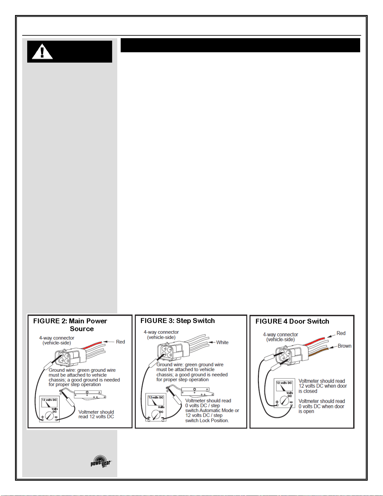
The step will not function if the ground to the control unit lost between the step control unit and the
vehicle chassis (the long green ground wire) or between the vehicle battery and the ground (negative
battery cable). Make sure the battery terminals and all wire connections are clean and tight. Verify that all
wires meet the minimum requirements specified in FIGURE 1 on PAGE 2.
General Service Note
s
KWIKEE STEP TESTING
PROCEDURES
1217 E. 7
th
St.
Mishawaka, IN 46544
www.powergearus.com

Troubleshooting and Test Procedure
s
The step test procedures outlined in this tip sheet are provided to troubleshoot and test all Kwikee IMGL
automatic electric step functions. The procedures are designed to initially check the basic functions of the
step separately from the RV wiring to determine whether or not the step is malfunctioning. The
procedures test various components of the step until the source of the malfunction is located. Using the
procedures will shorten and reduce the time spent troubleshooting.
Some portions of the test procedures require additional equipment. This equipment includes:
A voltmeter
A well charged 12V DC automotive battery
4-way connector/pigtail (Part #909306000, available from Kwikee)
** Read the entire procedure prior to testing **
TESTING THE STEP:
1. Inspect the step for visible damage that might restrict step operation.
2. Obtain a 4-way pigtail connector (part #909306000) from Kwikee.
3. Disconnect 4-way connector on underside of step and connect the step-half of the connector to the
four-way connector pigtail. See FIGURE 1 on PAGE 2.
4. Set a fully charged 12V DC automotive battery beside the step.
NOTE: Do not allow the battery terminals to come in contact with the step.
Complete a ground for the step tests by connecting a 10 gauge wire from the negative (-) battery
post to the green ground wire of the control unit.
WARNING
IMGL Control
Pre IMGL Control
Page 2of 4
82-ST0500 Kwikee Step Testing Procedures
Do not allow the battery
terminals to come in contact
with the step.

WARNING

Keep fingers, arms, and legs
clear of step mechanism while
performing these tests. Failure
to do so may result in person
injury.

WARNING

Step control wiring is only to
be used for step and step light
(provided with the step)
functions. Do not splice or tap
into any of the step wiring.
Failure to heed this warning
may result in failure of step
control, which may result in
loss of step function or fire in
the step control. Refer any
questions to the step
manufacturer
5. To supply power, attach the red wire from the pigtail to the battery’s positive (+) post. The step will
extend.
6. With the power and ground connections complete, all functions of the control unit can be checked
at the four wires of the pigtail. The brown wire is the door switch, the white wire is the step lockout
switch, and the yellow wire is the ignition override.
7. To retract the step, touch the brown wire to the negative (-) terminal.
8. To extend the step, remove the brown wire from the negative (-) terminal.
9. To test the ignition override feature, extend the step as in Step 8. With the step extended, connect
the white wire to the positive (+) terminal and attach the brown wire to the negative (-) terminal.
Next, touch the yellow wire to the battery’s positive (+) terminal. The step should retract. Remove
the brown wire and the step should extend.
10. If any of the step functions do not work, the source of the malfunction is either in the control unit
and/or the motor. Proceed to the “Testing the Motor” section on PAGE 3.
If all of the step functions do work, the malfunction is either in the door switch, step lockout switch, or
the vehicle wiring. Proceed to “Testing the 4-way Connector” section on PAGE 3.
To test the “Auto Extend” feature, touch the brown wire to the negative (-) terminal to retract the step.
While holding the brown wire to the negative (-) terminal, remove the yellow from the positive (+)
terminal. Touch the white wire to the positive (+) terminal. The step will stay retracted.
Now, remove the brown wire and the step should extend.
Next touch the brown wire to the negative (-) terminal. The step should stay extended.
CAUTION
Troubleshooting and Test Procedures, Continue
d
Page 3of 4
82-ST0500 Kwikee Step Testing Procedures

CAUTION

TESTING THE MOTOR:
Do not leave the wires
connected during this test
once the step has cycled
either in or out. Failure to
remove the wires from the
battery will burn out the motor
voiding any warranty
TESTING THE MOTOR
11. Disconnect the two-way connector between the step motor and the control unit. Connect the
motor’s red wire to the positive (+) terminal of the battery and touch the motor’s yellow wire to the
negative (-) terminal of the battery to extend the step. To retract the step, reverse the connections.
If the step extends and retracts during this test, the condition of the step motor is good.
NOTE: On steps with reverse polarity plug (Part #1800711) reverse the red
and yellow wire connections to perform the previous test.
TESTING THE 4-WAY CONNECTOR
12. To check the main power source, connect a voltmeter between the red wire from the 4-way
connector (vehicle half) and the ground terminal at the end of the control unit’s green ground wire
(see FIGURE 2). The reading should be a minimum of 12 volts DC.
If the voltage reading is low, there may be a loose or corroded connection at the battery, a low charge
level on the battery itself, or a poor ground. If the voltage reading is zero (0) volts, check the step
fuse/circuit breaker, all connections, and the condition of the wiring between the battery and the plug,
including the ground connection at the chassis.
13. To check the step lockout switch, connect a voltmeter between the white wire from the 4-way
connector (vehicle half) and the terminal at the end of the control unit’s green ground wire (see
FIGURE 3). The reading should be a minimum of 12 volts DC (the same as in STEP 12) with the
switch in one position, and zero (0) volts DC with the switch in the opposite position.
NOTE: Refer to vehicle OEM owner’s manual (or OEM requirements) which
will provide the Switch position of “on” or “off” for the step lock position.
If the voltmeter reads zero (0) volts when the step switch is the Automatic Mode position, there is a
problem in the step lockout switch circuit.
Check the 6 amp in-line fuse, the step lockout switch, and the condition of the circuit’s wiring and
terminal connections.
14. To check the door switch, connect a voltmeter between the red wire from the 4-way connector
(vehicle half) and the brown in the same connector (see FIGURE 4). The voltage should be a
minimum of 12 volts DC (the same as in STEP 12) when the door is closed and zero (0) volts when
the door is open
If the readings are incorrect, there is a problem with the switch. Check the door switch and the condition
of the circuit’s wiring and terminal connections.
Troubleshooting and Test Procedures, Continue
d
1217 E. 7
th
St.
Mishawaka, IN 46544
www.powergearus.com

Page 4of 4
82-ST0500 Kwikee Step Testing Procedures
15. To check the ignition override system, connect a voltmeter between the yellow wire from the 4-way
connector (vehicle half) and the ground terminal on the end of the control unit’s green ground wire
(see FIGURE 5). The voltage reading should be approximately 12 volts DC when ignition is on and
zero (0) volts when ignition is off.
If the reading is zero when the ignition is on, check all terminal connections, wiring, and the vehicle’s
ignition fuse.
NOTE: The step wiring circuit must be independent. No other device (i.e.
alarm systems, step well lights, etc) can be connected to the step wiring
circuit. Any device connected to the steps wiring can cause the step to
malfunction and will void the warranty.
16. For steps equipped with door switch only operation:
Connect the white jumper wire from the vehicle half of the four-way connector and the ground
terminal at the end of the control unit’s green ground wire (See Figure 6)
NOTE: Be sure to use the terminal with only the white wire.
The reading should be zero (0) volts DC. If the voltage reading is more, the white wire is connected to
12 volts DC and should be cut.
1217 E. 7
th
St.
Mishawaka, IN 46544
www.powergearus.com

FIGURE 6: Connecto
r
FIGURE 5: I
g
nition Override
Additional Reference Publications Located At
WWW.POWERGEARUS.COM
Document # Manual # Title
1422279 888 Electric Step Owners Manual #888
82-ST0501 N/A Step Identification Guide Tip Sheet

This manual suits for next models

2

Popular Control Unit manuals by other brands

ICP DAS USA I-8026W manual

ICP DAS USA

ICP DAS USA I-8026W manual

SMC Networks SYJ3000 manual

SMC Networks

SMC Networks SYJ3000 manual

Cavotec STD-302N-R user manual

Cavotec

Cavotec STD-302N-R user manual

Crestron FlipTop FT2 Series quick start

Crestron

Crestron FlipTop FT2 Series quick start

AUDAC WaveDynamics ANI Series quick start guide

AUDAC

AUDAC WaveDynamics ANI Series quick start guide

Burkert 2100 series quick start

Burkert

Burkert 2100 series quick start

GOK CGV Assembly and operating manual

GOK

GOK CGV Assembly and operating manual

TQ Ma8XxS user manual

TQ

TQ Ma8XxS user manual

Xenteq ISO Series user manual

Xenteq

Xenteq ISO Series user manual

Trane BAS-SVN213A-EN installation instructions

Trane

Trane BAS-SVN213A-EN installation instructions

Mitsubishi FR-A5ND instruction manual

Mitsubishi

Mitsubishi FR-A5ND instruction manual

Neoway G2 Hardware user's guide

Neoway

Neoway G2 Hardware user's guide

Dixon BAYCO 4040RD Installation & operating instructions

Dixon

Dixon BAYCO 4040RD Installation & operating instructions

Habasit PMR-07 General manual use and maintenance

Habasit

Habasit PMR-07 General manual use and maintenance

Nevco MPCX2 Football Operator instructions

Nevco

Nevco MPCX2 Football Operator instructions

Beninca CP.ZED230-E manual

Beninca

Beninca CP.ZED230-E manual

Swidget WI000UWA manual

Swidget

Swidget WI000UWA manual

Anritsu Network Master Pro MT1040A Operation manual

Anritsu

Anritsu Network Master Pro MT1040A Operation manual

manuals.online logo
manuals.online logoBrands
  • About & Mission
  • Contact us
  • Privacy Policy
  • Terms and Conditions

Copyright 2025 Manuals.Online. All Rights Reserved.