Acconeer XM112 Installation manual

HP module EVK hardware user guide
- XM112, XB112, LH112

HP module EVK hardware user guide – XM112, XB112, LH112
Page 2 of 41
© 2018 by Acconeer – All rights reserved 2022-08-25
HP module EVK hardware user guide
- XM112, XB112, LH112
Author: Acconeer
Version 1.2: 2022-08.25
Acconeer AB

HP module EVK hardware user guide – XM112, XB112, LH112
Page 3 of 41
2022-08-25 © 2018 by Acconeer – All rights reserved
Table of Contents
1 Overview of the HP module EVK. ....................................................................................................... 5
1.1 Introduction .............................................................................................................................. 5
2 Software for the Module EVK ............................................................................................................. 6
2.1 Software download .................................................................................................................. 6
2.2 Module software for XM112 ................................................................................................... 6
2.3 SDK for ATMEL SAME70 ..................................................................................................... 6
3 The HP Module EVK Hardware .......................................................................................................... 7
3.1 XB112 Breakout Board ............................................................................................................ 8
3.1.1 Overview ......................................................................................................................... 8
3.1.2 Power ............................................................................................................................. 10
3.1.3 Electrical Schematics..................................................................................................... 11
3.1.4 Bill of Material .............................................................................................................. 15
3.1.5 Component Placement Drawing .................................................................................... 17
3.1.6 Pinning/Connectors ....................................................................................................... 19
3.1.7 Buttons ........................................................................................................................... 22
3.2 HP Module ............................................................................................................................. 23
3.2.1 Overview ....................................................................................................................... 23
3.2.2 Electrical Schematics..................................................................................................... 25
3.2.3 Bill of Material .............................................................................................................. 29
3.2.4 Component Placement Drawing .................................................................................... 30
3.2.5 Pinning ........................................................................................................................... 32
3.3 Lens Evaluation Kit LH112 ................................................................................................... 33
3.3.1 Overview ....................................................................................................................... 33
3.3.2 Contents and assembly .................................................................................................. 33
3.3.3 Lens Performance .......................................................................................................... 35
4 Flashing of XM112 via USB-UART Interface .................................................................................. 36
4.1 Updating the Software ........................................................................................................... 36
4.1.1 Install Tools ................................................................................................................... 36
4.1.2 Upgrade Procedure ........................................................................................................ 36
5 Safety 38
5.1 Electrostatic precautions ........................................................................................................ 38
6 Regulatory Information ...................................................................................................................... 39
7 Revision History ................................................................................................................................. 40
8 Disclaimer .......................................................................................................................................... 41

HP module EVK hardware user guide – XM112, XB112, LH112
Page 4 of 41
© 2018 by Acconeer – All rights reserved 2022-08-25

HP module EVK hardware user guide – XM112, XB112, LH112
Page 5 of 41
2022-08-25 © 2018 by Acconeer – All rights reserved
1 Overview of the HP module EVK.
1.1 Introduction
The HP Module Evaluation Kit (The EVK) is a platform for evaluating the HP Module. The module is
based on the Acconeer A111 sensor, which is an optimized low-power, high-precision 60 GHz radar
in one package solution with integrated Baseband, RF front-end and Antenna. In the HP Module The
A111 sensor is integrated together with an M7 processor (Atmel SAME70) which facilitates signal
processing for advanced use cases. For an introduction to Acconeer’s technology and product offer
refer to “Introduction to Acconeer’s sensor technology”, available at the Acconeer website.
The EVK consists of
One HP Module featuring A111 and an Atmel SAME70 MCU. The module is not pre-flashed and
an XB112 is needed to easily flash it.
One XB112 breakout board which enables connection to external devices.
LH112

HP module EVK hardware user guide – XM112, XB112, LH112
Page 6 of 41
© 2018 by Acconeer – All rights reserved 2022-08-25
2 Software for the Module EVK
2.1 Software download
All software is available for download at https://www.acconeer.com/products, more details about the
software offer and structure can be found in the document “Introduction to Acconeer’s sensor
technology”, available at the Acconeer website.
For the HP Module Acconeer provides two deliveries, a software development kit (SDK) for ATMEL
SAME70 and a module software image for XM112. Details about the software offer can be found in
the document “Introduction to Acconeer’s sensor technology”, available at the Acconeer website.
2.2 Module software for XM112
The HP Module software enable register-based access to radar functionality from external devices
connected to the HP Module. The module software is delivered as an image.
Typical usages of the HP Module software are:
1. Integration of radar functionality in your product to decrease development cost and time to
market.
2. Module evaluation and algorithm development in Python together with the “Acconeer Python
Exploration Tool” that is available for download on GitHub. https://github.com/acconeer/
The HP Module software provides a rich register-based API that can be accessed over UART, SPI and
I2C1.
The Module software will initially support the following services and detectors:
- Power Bin Service
- Envelope Service
- IQ Data Service
- Distance peak detector with fixed threshold
Support for more detectors is planned for future module software releases.
2.3 SDK for ATMEL SAME70
For users that wish to use the module MCU to implement their own applications and other SW
components we also provide an SDK.
The Acconeer SDK comes with an API (Application Programming Interface). Acconeer provides
several service oriented example applications, as well as customer guidelines for application
development when utilizing the API. All APIs provided by Acconeer are documented in the SDK.
1 The I2C support is planned but is not available at the time of writing.

HP module EVK hardware user guide – XM112, XB112, LH112
Page 7 of 41
2022-08-25 © 2018 by Acconeer – All rights reserved
3 The HP Module EVK Hardware
Figure 1 shows the block diagram for the HP Module Evaluation Kit
A111
24MHz XTAL
XM112
ATSAME70
ENABLE
INTERRUPT
1.8V
SPI external
I2C
UART[0,2,4]
SWD
MCU_INT
MCU_GPIO
ERASE
NRST
XB112 Board to board connector
SPI internal
12MHz XTAL
5V
1.8V
1.8V
FTDI
FT230XS
Misc GPIO
pin header
MCU_INT
MCU_GPIO
XM112 Board to board connector
JTAG/SWD
pin header
40-pin
connector
(NM)
FTDI
FT4222H
USB Connector 2 USB Connector 1
UART2
UART4
MCU_INT
MCU_GPIO
ERASE
NRST
SWD
I2C
NRST
Button
ERASE
Button
UART0
Switched
Power
Regulator
Dual
LDO
1.8V
1.8V
XB112
Figure 1 The EVK block diagram.

HP module EVK hardware user guide – XM112, XB112, LH112
Page 8 of 41
© 2018 by Acconeer – All rights reserved 2022-08-25
3.1 XB112 Breakout Board
The XB112 is Acconeer’s breakout board and part of the Module EVK.
3.1.1 Overview
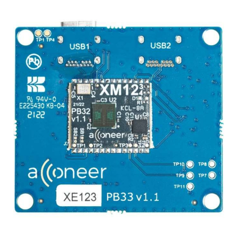
The XB112 is a breakout-board designed for the XM112 Radar Module. It makes the interfaces from
the XM112 radar module accessible for evaluation and debug. It also enables flashing of the XM112
via USB-UART or SWD. The XM112 is connected to the XB112 via a board-to-board connector on
the top side of the PCB. Below you will find pictures of both front and back side of the breakout
board.
Picture 1 shows the XB112 connector board, front side.

HP module EVK hardware user guide – XM112, XB112, LH112
Page 9 of 41
2022-08-25 © 2018 by Acconeer – All rights reserved
Picture 2 shows the breakout board, XB112, back side.

HP module EVK hardware user guide – XM112, XB112, LH112
Page 10 of 41
© 2018 by Acconeer – All rights reserved 2022-08-25
3.1.2 Power
The EVK is powered via the USB connectors on XB112. USB1 powers the USB-UART chip (U4) and
the XM112. USB2 powers the USB-SPI chip (U5). If no SPI data is needed, the USB2 can be left
unconnected. USB1 must however always be connected. If the USB-UART interface is not used, a
dedicated USB charger can be inserted to USB1.
When the power LED on the XB112 is lit, the breakout board and the XM112 radar module (if
connected to the board-to-board connector on the top side of XB112) are powered on and ready for
use. For details regarding the power management on XB112, refer to the XB112 product brief.

HP module EVK hardware user guide – XM112, XB112, LH112
Page 11 of 41
2022-08-25 © 2018 by Acconeer – All rights reserved
3.1.3 Electrical Schematics
On the following pages, please find the electrical schematics for the XB112.

HP module EVK hardware user guide – XM112, XB112, LH112
Page 12 of 41
© 2018 by Acconeer – All rights reserved 2022-08-25

HP module EVK hardware user guide – XM112, XB112, LH112
Page 13 of 41
2022-08-25 © 2018 by Acconeer – All rights reserved

HP module EVK hardware user guide – XM112, XB112, LH112
Page 14 of 41
© 2018 by Acconeer – All rights reserved 2022-08-25

HP module EVK hardware user guide – XM112, XB112, LH112
Page 15 of 41
2022-08-25 © 2018 Acconeer – All rights reserved
3.1.4 Bill of Material
Table 1 shows the BOM for the XB112
Table 1 The BOM for the XB112.
Component Ref. Specification QTY Value Comment
C2,C9,C10,C11,C16,C
18,C20,C22,C32,C33,
C35
100/NF/K/50V/X7R/1005 11 100nF
C24
100/PF/J/10V/NP0,C0G/10
05
1
100pF
C3,C14 10/NF/K/16V/X7R/1005 2 10nF
C12,C13 10/UF/M/10V/X5R/1005 2 10uF
C1,C6,C7,C8,C31 1/UF/K/10V/X5R/1005 5 1uF
C23 470/NF/K/10V/X5R/1005 1 470nF
C4,C5 47/PF/J/50V/C0G/1005 2 47pF
C25,C26 8/PF/C/50V/NP0,C0G/1005
2 8pF
C15,C17,C19,C21,C
34
1608 10% 10V X5R 4.7uF 5 4.7uF
R5,R7,R10,R11,R15,
R20,R21
1005 J 0 7 0 Ohm
R3,R4,R14,R22,R23 1005 F 10K 5 10kOhm
R12 1005 F 12K 1 12kOhm Accuracy 1%
R1,R2 1005 F 27 2 27Ohm
R9 47/KOHM/F/1005 1 47kOhm
R16,R17 4.7/KOHM/F/1005 2 4.7kOhm
R24 10/OHM/F/1005 1 10 Ohm
J1,J2 10118194-0001LF/Micro B
USB 2.0 Receptacle
2 N/A Manufacturer: Amphenol
U1 BD7004NUX/Dual output
5V to 1.8V LDO
1 N/A Manufacturer: Rohm
J4 DF40C-30DP-
0.4V51/XM112 30 pin B2B
connector plug
1 N/A Manufacturer: Hirose
L1 DFE252012R-H-1ROM=p2 1 1uH
Y1 FL1200112/CRYSTAL_12M
Hz
1 N/A

HP module EVK hardware user guide – XM112, XB112, LH112
Page 16 of 41
© 2018 by Acconeer – All rights reserved 2022-08-25
U4 FT230XS-R/USB to UART
bridge
1 N/A
U5 FT4222H/USB to SPI
bridge
1 N/A
J5,J6 FTSH_105_04_F_DH/SWD
Connector, Right angle 2x5
pin header
2 N/A Manufacturer: Samtech
J7,J8 SWITCH TACTILE SPST-
NO 0.05A 12
434331045822
2 N/A Manufacturer: Wurth
Electronics
B1,B2 MI0805K601R_10/Ferrite
Bead
2 N/A
U3 NC7SZ00P5X/NAND gate 1 N/A
U2 TPS62061DSGR 1 N/A
D1 LTST-C193KRKT-5A/LED
RED
1 N/A

HP module EVK hardware user guide – XM112, XB112, LH112
Page 17 of 41
2022-08-25 © 2018 by Acconeer – All rights reserved
3.1.5 Component Placement Drawing
The component placement drawing of XB112 is found below.
Top Side:

HP module EVK hardware user guide – XM112, XB112, LH112
Page 18 of 41
© 2018 by Acconeer – All rights reserved 2022-08-25
Bottom Side:

HP module EVK hardware user guide – XM112, XB112, LH112
Page 19 of 41
2022-08-25 © 2018 by Acconeer – All rights reserved
3.1.6 Pinning/Connectors
3.1.6.1 USB1 (J1)
USB1 is used as power supply for the XB112 and the XM112. It is also used for flashing and
communicating over UART. USB1 is connected to the FTDI chip FT230XS which converts the
UART interface from XM112 into USB signals. The pinout of USB1 is shown in
.
Table 2. The pinout of J1.
Pin Number Signal
1 VBUS
2 D-
3 D+
4 ID (GND)
5 GND
3.1.6.2 USB2 (J2)
USB2 is used for high speed data read out from the module SPI interface. It is converted to USB via
the FTDI chip FT4222H. The pinout of USB2 is shown in Table 3.
Table 3. The pinout of J2.
Pin Number
Signal
1 VBUS
2 D-
3 D+
4 ID (GND)
5 GND

HP module EVK hardware user guide – XM112, XB112, LH112
Page 20 of 41
© 2018 by Acconeer – All rights reserved 2022-08-25
3.1.6.3 2x20 pin header (J3)
The 2x20 pin header (1.27mm pitch) is not mounted. The reason is that it is intended for Acconeer
internal use only. All the interfaces available in the 2x20 pin header are also available in the other
connectors. The pinout of the 2x20 pin header is shown in Table 4.
Table 4. The pinout of J3.
Pin Number
Signal
Pin Number
Signal
1 NC 2 ERASE
3 GND 4 GND
5 NC 6 UART0_RX_TX
7 SPI_MOSI 8 UART0_TXRX
9 SPI_MISO 10 GND
11 GND 12 SPI_CLK
13 SPI_SS 14 GND
15 NC 16 TRACESWO
17 GND 18 SWDCLK
19 GND 20 GND
21 GND 22 GND
23 GND 24 1V8
25 GND 26 GND
27 GND 28 MCU_GPIO
29 GND 30 MCU_INT
31 GND 32 GND
33 GND 34 SWDIO
35 GND 36 NRST
37 GND 38 1V8
Other manuals for XM112
1
This manual suits for next models
2
Table of contents
Other Acconeer Control Unit manuals