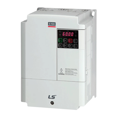
LSIS S100 Series User manual

S100 PROFInet Option Manual
i
Thank you for using our S100 PROFInet option module
Safety PRECAUTIONS
Always follow safety instructions to prevent accidents and potential hazards from occurring.
Safety precautions are classified into “WARNING” and “CAUTION” and their meanings are as
follows:
WARNING Improper operation may result in serious personal injury or death.
CAUTION Improper operation may result in slight to medium personal injury
or property damage
The indicated illustrations on the product and in the manual have the following meanings.
Danger may be present. Read the message and follow the instructions carefully.
Particular attention should be paid because danger of an electric shock may be present.
Keep operating instructions handy for quick reference.
Read the operating instructions carefully to fully understand the functions of the S100 series
and to use it properly.
CAUTION
Be cautious, when handling the CMOS components of the communication module.
Static may lead to malfunctioning of the product.
Turn off the inverter power, when changing the communication cable.
Otherwise, you may damage the module or a communication error may occur.
Make sure to insert the Communication module connector to the inverter precisely.
Otherwise, you may damage the module or a communication error may occur.
Check the parameter unit before setting up the parameter.
Otherwise, a communication error may occur.

S100 PROFInet Option Manual
ii
Table of Contents
1About the Product........................................................................................... 1
1.1 PROFInet Technical Features................................................................. 1
1.2 Included Items ........................................................................................ 1
1.3 GSDML File............................................................................................ 1
2Part Names and Installation............................................................................ 2
2.1 Exterior................................................................................................... 2
2.2 Installation .............................................................................................. 2
2.3 PROFInet Communication Module Front Panel ...................................... 5
3Network Connections...................................................................................... 7
3.1 Network Cable Contacts......................................................................... 7
3.2Communication Cable Connector ........................................................... 7
3.3 Network Cable Specification................................................................... 7
4PROFInet Communication Related Keypad Parameters............................... 8
5Keypad Parameters Related to PROFInet Communication Module........... 10
5.1 CNF Group........................................................................................... 10
5.2 DRV Group........................................................................................... 10
5.3 COM Group...........................................................................................11
5.4 PRT Group............................................................................................ 13
6PROFIdrive Status Diagram.......................................................................... 14
7Supported PROFIdrive Cyclic Telegram ...................................................... 16
7.1 Standard Telegram (Mode : 0) .............................................................. 16
7.2 Vendor Specific Telegram (Mode : 1).................................................... 16
8Supported PROFIdrive Parameters.............................................................. 22
9Fault Message Counter (PNU[944]) and Fault Number (PNU[947]) ............ 24
10 Accessing the S100 Common Parameters using the PROFIdrive
Parameters..................................................................................................... 28
11 Accessing S100 Inverter Parameters using the PROFInet Record Data
Object............................................................................................................. 30
12 Processing the Alarms.................................................................................. 31
13 Trouble Shooting........................................................................................... 32
S100 PROFInet Option Manual
1
1 About the Product
The LSIS S100 PROFInet communication module (model CJ-S7M1) provides
PROFInet network communication for the LV-S100 inverter. PROFInet is a
communication protocol compliant with IEC 61158 Type 10. The PROFInet
communication module provides full-duplex data transfer which enables real-time
communication without transmission collisions. Using a PROFInet connection, the
S100 inverter can be controlled and monitored via a PLC sequence program or any
master PLC module. In addition, PROFInet is easy to connect, enabling faster
installation and easier maintenance.
1.1 PROFInet Technical Features
Item
Description
Communication protocol
PROFInet IO CC-A
Communication speed
100 Mbps
Communication type
Full Duplex
Distance
100m (Twisted Pair)
Max. number of Node
64 ea
Service
PROFIdrive Class 1
Topology
Line, Tree, Star topology
1.2 Included Items
This product is consisting of these kinds of parts.
- PROFInet Communication Module board (CPNT- S100): 1 ea
- PROFInet Module manual: 1 ea
- Brass Bar(M3xL23): 1 ea
- Brass Bar(M3xL17.3): 1 ea
- Fixed Screw(M3xL8): 2 ea
1.3 GSDML File
The GSDML file contains information about the PROFInet communication module
installed in an inverter. When you configure the PROFInet network, the network
configuration software requires the GSDML file.
** You can download the file from http://www.lsis.co.kr/.

S100 PROFInet Option Manual
2
(2)
(1)
2 Part Names and Installation
2.1 Exterior
2.2 Installation
Warning) Connect a communication network after the power supply is off. If PROFInet
communication module is removed or installed, the power supply should be switched
off. Otherwise, the S100 inverter will be damaged entirely.
Take off PROFInet communication module from the product after the power supply is
totally discharged.
Unfasten the front cover fixing bolt
to remove the front cover and remove
I/O cover((1), (2)) from
a dedicated S100 inverter
for communication.

S100 PROFInet Option Manual
3
■Remove the keypad (3).
■Unfasten a screw from
I/O board and
fasten the prepared
brass bar(4).
■Mount PROFInet communication Module
and fasten the removed screw(6)
and the included screw(7).
(5)
(6)
(7)
(3)
(4)

S100 PROFInet Option Manual
4
■Install the keypad (8) at first and
the communication module
cover(9) in order.
■Install the front cover(10) again
And installation is completed.
(9)
(8)
(10)

S100 PROFInet Option Manual
5
2.3 PROFInet Communication Module Front Panel
Indicator
Color
Description
Status
Remarks
LED0
LINK1/ACT1
Green
Normal
operation
ON
LINK1 is connected
to a network.
OFF
LINK1 is not
connected to a
network
Yellow
Normal
operation
OFF
Network LINK1 is not
transmitting/receiving
data
Flashing
Data transmission
between the Master
unit and the
communication
module is in progress
at network LINK1.
LED1
LINK2/ACT2
Green
Normal
operation
ON
LINK2 is connected
to a network.
OFF
LINK2 is not
connected to a
network
Yellow
Normal
operation
OFF
Network LINK1 is not
transmitting/receiving
RUN
ERROR
LINK1
LINK2

S100 PROFInet Option Manual
6
Indicator
Color
Description
Status
Remarks
data
Flashing
Data transmission
between the master
unit and the
communication
module is in progress
at network LINK2.
LED2
ERROR
Red
Normal
operation
OFF
Communication
between the
communication
module and the
inverter is normal.
Communication
fault
CPU and
ERROR
indicators flash
simultaneously
Communication error
occurred between the
communication
module and the
inverter
CPU and
ERROR
indicators flash
asynchronously,
in 2 second
intervals
Abnormal
communication
conditions exist
between the
communication
module and the
inverter.
ON
The communication
module failed to boot
up.
LED3
CPU
Green
Abnormal
operation
ON
The CPU is not
operating.
OFF
Normal
operation
Flashing
(1 second
intervals)
The communication
module is installed
correctly in the
inverter.

S100 PROFInet Option Manual
7
3 Network Connections
3.1 Network Cable Contacts
Pin No.
Signal
Description
Cable Color
1
TX+
Data Transmission (+)
White/Yellow
2
TX-
Data Transmission (-)
Yellow
3
RX+
Data Reception (+)
White/Green
4
NONE
Not Used
Blue
5
NONE
Not Used
White/Blue
6
RX-
Data Reception (-)
Green
7
NONE
Not Used
White/Brown
8
NONE
Not Used
Brown
3.2 Communication Cable Connector
** Wires connected to pin #1 and pin #2 must be twisted.
** Wires connected to pin #3 and pin #6 must be twisted.
3.3 Network Cable Specification
PROFInet network communication requires STP (category 6a, or higher) network
cables.
1
8
1
2
3
4
5
6
7
8

S100 PROFInet Option Manual
8
4 PROFInet Communication Related Keypad Parameters
To operate an S100 inverter using the PROFInet communication module, set DRV-06
(Cmd Source) to [4 Fieldbus]. Set DRV-07 (Freq Ref Src) to [8 Fieldbus] to provide a
frequency reference to the inverter using the PROFInet communication module.
Code
Parameter Name
Default
Description
CNF
30 Option-1 Type
-
When the S100 PROFInet communication
module is installed, the module type
“PROFInet” is automatically detected and
displayed. Note 1)
DRV
06 Cmd Source
1 Fx/Rx-1
0
Keypad
1
Fx/Rx-1
2
Fx/Rx-2
3
Int 485
4
Fieldbus
5
UserSeqLink
07 Freq Ref Src
0 Keypad-1
0
Keypad-1
1
Keypad-2
2
V1
4
V2
5
I2
6
Int 485
8
FieldBus
9
UserSeqLink
12
Pulse
COM
06 FBus S/W Ver
-
-
09 FBus Led
-
-
10 opt para-1
0
IP - 1
11 opt para-2
0
IP –2

S100 PROFInet Option Manual
9
12 opt para-3
0
IP –3
13 opt para-4
0
IP - 4
14 opt para-5
0
Subnet Mask - 1
15 opt para-6
0
Subnet Mask - 2
16 opt para-7
0
Subnet Mask –3
17 opt para-8
0
Subnet Mask - 4
18 opt para-9
0
Gateway - 1
19 opt para-10
0
Gateway - 2
20 opt para-11
0
Gateway - 3
21 opt para-12
0
Gateway - 4
22 opt para-13
0
Mode (0:STD Telegram1, 1: Vendor Specific
Telegram)
PRT
12 Lost Cmd Source
0 None
0
None
1
Free-Run
2
Dec
3
Hold Input
4
Hold Output
5
Lost Preset
13 Lost Cmd Time
1.0
0.1–120 [s]
14 Lost Preset F
0.00
0.50–60.00 [Hz]

S100 PROFInet Option Manual
10
5 Keypad Parameters Related to PROFInet Communication Module
5.1 CNF Group
5.1.1 [CNF-30] Option-1 Type: the type of device installed in the
module slot 1
Automatically detects and displays the type of communication module installed.
“PROFInet” is displayed when a PROFInet communication module is installed in the
S100 inverter.
5.2 DRV Group
5.2.1 [DRV-06] Cmd Source: Command Source Selection
Selects the command source for the S100 inverter. Set the parameter to [4 FieldBus]
to set PROFInet communication as the command source.
5.2.2 [DRV-07] Freq Ref Src: Frequency Reference Source Selection
Selects the frequency reference source for the S100 inverter. Set the parameter to [8
FieldBus] to set PROFInet communication as the frequency reference source.

S100 PROFInet Option Manual
11
5.3 COM Group
5.3.1 [COM-06] FBus S/W Ver: Communication Module Software
Version
Automatically detects and displays the software version of the currently installed
communication module.
5.3.2 [COM-09] FBus LED: Communication Module Status Indicator
(LED) Information
Displays the communication module’s status indicator (LED) information on the
inverter’s keypad. For more information, refer to <2 Part Names and Installation>.
An example of “[COM-09] FBus” LED status displayed on the keypad
Indicator Name
LINK1/ACT1
LINK2/ACT2
ERR
CPU
Status
OFF
ON
ON
ON

S100 PROFInet Option Manual
12
5.3.3 [COM-10–21] IP Address, Subnet Mask, Gateway Settings
The S100 PROFInet communication module supports IPv4 protocol. All addresses
and masks are expressed with four decimal numbers between 0 and 255, each
separated by a dot (xxx.xxx.xxx.xxx). A PLC can forcibly reset the IP address by
sending a DCP packet.
For example, when programming a PLC in Siemens TIA, you can select Set IP
address in the project ( ) to allow the PLC to send a DCP packet to a
communication module to set an IP address. If you select IP address is set directly
at the device ( ), the PLC reads the IP address set at the communication module
and uses it for PROFInet network communication, instead of resetting the IP.
5.3.4 [COM-22] Telegram Mode Settings
The S100 PROFInet Communication module supports two different types of telegrams.
Refer to <7 Supported PROFIdrive Cyclic Telegram> for the supported telegram
types and the details.
Setting
Selected Telegram Type
0
Standard Telegram
1
Vendor Specific Telegram
5.3.5 [COM-94] Comm Update
Press Yes to reflect the values setup with keypad on the PROFInet option.

S100 PROFInet Option Manual
13
5.4 PRT Group
5.4.1 [PRT-12] Lost Cmd Mode: Lost Command Mode Options
Select the inverter’s operation mode for a “Lost Command” condition caused by a
communication error.
The following table lists available operation modes.
Settings
Description
0
None
Speed reference becomes the operating frequency, without
a protective operation.
1
Free-Run
The inverter cuts off the output and the motor free-runs.
2
Dec
The inverter performs a deceleration stop according to the
time set at “Trip Dec Time.”
3
Hold Input
The inverter keeps operating using the speed reference
received before the command loss.
4
Hold Output
The inverter keeps operating using the operation frequency
it was operating at before the command loss.
5
Lost Preset
The inverter operates using the frequency reference set at
Pr-14 “Lost Preset F.”
5.4.2 [PRT-13] Lost Cmd Time: Lost Command Decision Time
Sets the time taken for the inverter to decide that a command has been lost, and
apply the “Lost Command Modes” set at [PRT-12]. The setting range is from 0.1–120
seconds.
5.4.3 [PRT-14] Lost Preset F: Frequency Reference for Lost
Command
Sets a protective function that allows the inverter to run at a frequency reference that
is pre-set at [PRT-14], when command via the communication module is lost. The
setting range is between the start frequency and the maximum frequency [Hz].

S100 PROFInet Option Manual
14
6 PROFIdrive Status Diagram
The following diagram shows the operation status that the PROFInet communication
module uses.
Status
Description
S1: Switching On Inhibited
The communication module cannot be switched ON at
the moment.
S2: Ready For Switching On
The communication module can be switched ON at any
moment.
S3: Ready For Operation
Communication module operation is ready to be enabled.
S4: Operation enable
The motor is running.
Status transitions are directed by the commands that are periodically transmitted from

S100 PROFInet Option Manual
15
the PLC, and the command types are as follows. Refer to <7.2.1 Control word
(STW1)> for more information.
•NoQuickStop Command
•NoCoastStop Command
•SwitchOFF Command
•SwitchON Command
•OperationEnable Command
•OperationDisable Command
•QuickStop Command
•CoastStop Command
The following table lists status transition events and the inverter operations:
Source Status
Target Status
Event
Action (Inverter operation)
“Switch On
Inhibited”
“Ready For
Switching On”
"SwitchOFF"
and "NoQuickStop"
and "NoCoastStop"
None (Motor is stopped.)
“Ready For
Switching On”
“Switch On
Inhibited”
"QuickStop"
or
"CoastStop"
None (Motor is stopped.)
“Ready For
Switching On”
“Ready For
Operation”
"SwitchON"
None (Motor is stopped.)
“Ready For
Operation”
“Ready For
Switching On”
"SwitchOFF"
None (Motor is stopped.)
“Ready For
Operation”
“Operation”
"OperationEnable"
Motor is run.
“Operation”
“Ready For
Operation”
"OperationDisable"
Motor is stopped (the S100
inverter stops the motor
according to the ADV-8 “Stop
Mode” settings).
“Operation”
“Switch On
Inhibited”
"CoastStop"
Motor is stopped (Free Run
Stop).
“Operation”
“Switch On
Inhibited”
"QuickStop"
Motor is stopped (the S100
inverter stops the motor
according to the ADV-8 “Stop
Mode” settings).

S100 PROFInet Option Manual
16
7 Supported PROFIdrive Cyclic Telegram
The S100 communication module supports “Standard” and “Vendor Specific”
telegrams. On a PROFInet network, it can exchange cyclic telegrams with a PLC, at a
minimum cycle time of 8 ms. Each telegram is expressed as a submodule in
PROFInet network communication, and can be assigned to either Slot1 or Subslot 2
at the communication module.
7.1 Standard Telegram (Mode : 0)
Standard telegram1
Byte 1-2
Byte 3-4
PLC to S100
Control word (STW1)
Setpoint value
S100 to PLC
Status word (ZSW1)
Actual speed value
7.2 Vendor Specific Telegram (Mode : 1)
Vendor Specific
telegram1
Byte 1-2
Byte 3-4
Byte 5-6
Byte 7-8
Byte 9-10
PLC to S100
Control
word
(STW1)
Setpoint
value
Dummy
Dummy
Dummy
S100 to PLC
Status word
(ZSW1)
Actual
speed value
Alarm Info
Torque
Current
The following table lists settings for Standard and Vendor Specific Telegrams.
7.2.1 Control word (STW1)
Bit
Name
Value
Description
0
ON
1
Ready for operation
(Operation by a PLC is available.)
OFF1
0
NOT Ready for operation
(Operation by a PLC is not available.)
1
No OFF2
1
OFF2 (Coast Stop) feature is disabled. Current
operation is maintained.
OFF2 (Coast
Stop)
0
Stops the motor using a free-run stop (emergency
stop).
2
No OFF3
1
OFF3 (Quick Stop) feature is disabled. Current
operation is maintained.

S100 PROFInet Option Manual
17
Bit
Name
Value
Description
OFF3 (Quick Stop)
0
Stops the motor using the setting at S100 inverter
(ADV-8 “Stop Mode”).
3
Enable Operation
1
Operates the motor using the Setpoint value
(frequency reference received from a PLC via the
PROFInet network communication.
Disable Operation
0
Stops the motor using the setting at S100 inverter
(ADV-8 “Stop Mode”).
4
Enable Ramp
Generator
1
Performs acceleration and deceleration based on
the acceleration and deceleration time settings at
S100 inverter (PAR->DRV) to reach the Setpoint
(frequency reference).
Reset Ramp
Generator
0
Forces the operation frequency to “0.” (Operating
frequency drops to “0” after decelerating based on
the Dec Time set at the inverter).
5
Unfreeze Ramp
Generator
1
A fixed Ramp Generator operation is not
assigned.Acceleration and deceleration is
performed based on theAcc/Dec times configured
in the inverter’s Drive group (PAR->DRV)
parameter settings to to reach the Setpoint
(frequency reference).
Freeze Ramp
Generator
0
Speed reference from the PLC is ignored and the
Ramp Gernerator operation is fixed. The motor is
operated via the network communication by the
PROFInet, and the current operation frequency is
maintained.
6
Enable Setpoint
1
The motor is operated based on the speed
reference from the PLC.
Disable Setpoint
0
Forces the motor operation frequency to “0.”
7
FaultAcknowledge
(0 ->
1)
Set to 1 to release fault conditions at the S100
inverter.
8
Jog1 ON/OFF
-
Not supported
9
Jog2 ON/OFF
-
Not supported
10
Control By PLC
1
The S100 inverter is controlled by the PLC’s
control word (STW1) received via the PROFInet
network communication.
No Control By
PLC
0
The PLC’s control word (STW1) received via the
PROFInet network communication is ignored.
11–15
-
-
Reserved

S100 PROFInet Option Manual
18
The status transition explained in <10. PROFIdrive Operation Diagram> can be
performed by setting the four control word bits, from bit 0 to bit 3. For example, setting
the four bits to 1 (XXXX XXXX XXXX 1111) changes the status to “Operation.”
Note
“X” in the bit setting example indicates that the relevant bit can be set to either 0 or 1
without affecting the control word bit settings.
The following table lists the status transition controlled by the control word bits (Bits 0
to 3).
Command
Bit3
Bit2
Bit1
Bit0
QuickStop
X
0
X
X
CoastStop
X
X
0
X
NoQuickStop
X
1
X
X
NoCoastStop
X
X
1
X
SwitchOFF
X
1
1
0
SwitchON
X
1
1
1
OperationEnable
1
1
1
1
OperationDisable
0
1
1
1
Internally, the control uses the inverter’s operation command at communication
address 0x0382, and the Control word (STW1) for basic motor operation uses
address 0x47F (bits 0, 1, 2, 3, 4, 5, 6, 10). When a PLC sets the bits at 0x47F, motor
operation is possible simply by providing a frequency reference.
Example) Bit Settings for Motor Operation
Bit
Bit10
Bit9
Bit8
Bit7
Bit6
Bit5
Bit4
Bit3
Bit2
Bit1
Bit0
Setting
1
–Note)
–Note)
0
1
1
1
1
1
1
1
Note) ’-‘ indicates that the bit can be set to either 0 or 1 without affecting the motor operation.
Other manuals for S100 Series
7
Table of contents
Other LSIS Control Unit manuals

LSIS
LSIS XGT Series User manual

LSIS
LSIS XGT Series User manual

LSIS
LSIS CENT-S100 User manual

LSIS
LSIS XGT Series User manual

LSIS
LSIS XBL-EIPT User manual

LSIS
LSIS Starvert iG5A Series User manual

LSIS
LSIS S100 Series User manual

LSIS
LSIS XGT Series User manual

LSIS
LSIS XGT Series User manual

LSIS
LSIS XGT Series User manual
Popular Control Unit manuals by other brands

Novoferm
Novoferm HAD MS manual

Emerson
Emerson YARWAY 9100 ARC Series Installation, operation and maintenance instructions

Grundfos
Grundfos CU 361 manual

Allen-Bradley
Allen-Bradley ArmorBlock MaXum B Series installation instructions

Elektrogas
Elektrogas VMR01OTN manual

LOVATO ELECTRIC
LOVATO ELECTRIC EXP10 14 instruction manual