Page 3of 7
3010002679 Rev 0C Owner’s Manual In Wall Slide Out System
•Always make sure that the
slideout room path is clear
of people and objects
before and during
operation of the slideout
room.
•Always keep away from
the slide rails when the
room is being operated.
The gear assembly may
pinch or catch on loose
clothing causing personal
injury.
Fault Diagnostics/Troubleshooting
This control has the ability to detect and display several faults. When a fault is detected, the
room movement will stop and two (2) different LED’s will flash in a pattern.
•The FAULT CODE LED (FIGURE 4, page 2) will flash RED a number of times
corresponding to a specific fault code. Refer to the FAULT CODES chart on to best
determine what caused the fault.
•The ROOM MOVEMENT LED (FIGURE 4, page 2) will flash GREEN a number of
times corresponding to which motor had the associated fault.
For example: if you are seeing four (4) REDflashes and two (2) GREEN
flashes, it means that there is a motor fault on motor 2.
There are two (2) types of faults, MINOR and MAJOR, and fault must be cleared in order for
the room to operate.
•MINOR faults can be cleared by pushing and releasing the IN or OUT buttons on
the wall touchpad (FIGURE 4, page 2).
•MAJOR faults must be cleared by pushing and releasing the SET STOPS/CLEAR
FAULTS button located the back of the wall touchpad (FIGURE 2, page 2).
Note: For major faults, the control must be overridden by following the EMERGENCY
RETRACT MODE in the OVERRIDE MODES (page 4). The control will then have to be re-
programmed by an O.E.M. authorized dealer when the problem is repaired.
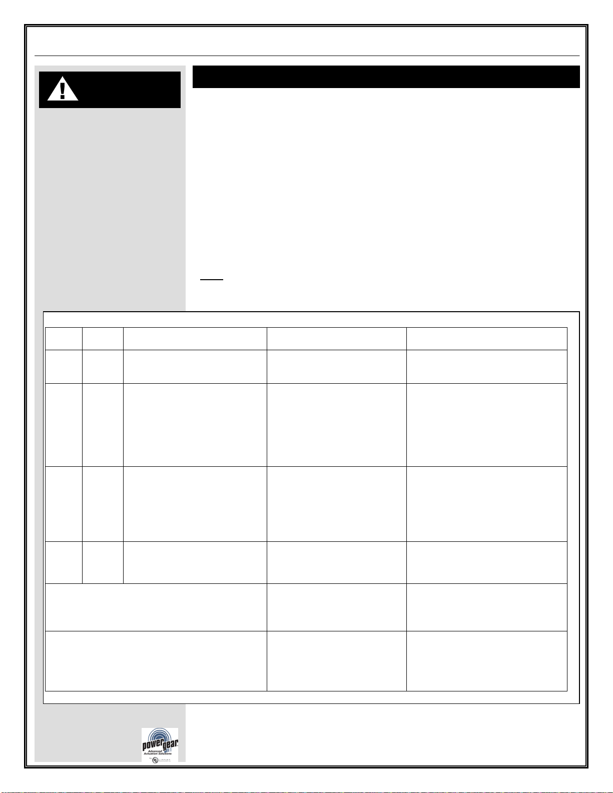
Description Possible Cause Possible Solutions
1 Major Stops not programmed
•Stops were cleared
•Stops were improperly set
Stops need to be programmed by an
authorized service facility.
2 Minor System Fault •Obstruction present
•Excessive system drag
Run room in opposite direction. If
room continues to move in the
opposite direction, remove
obstruction, excessive weight in room
or repair of damaged component. If
room stops moving in opposite
direction, observe fault code and
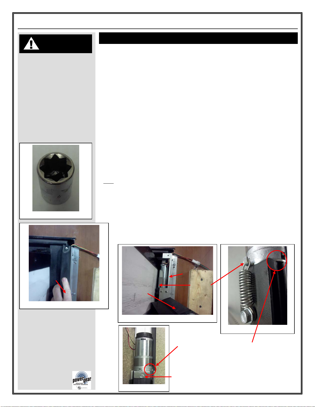
4 Major Motor Fault •Bad or loose connection
•Defective harness
•Open or shorted motor
•Check all connections at control
box and motor.
•Check the harness for broken
wires.
•Put 12.0 VDC direct to the
motor. If it does not run replace
6 Minor Excessive Battery Voltage Supply voltage to control box is
17.0 V DC or greater.
Check 2-pin power connector at
control box. If the voltage is 17.0
VDC or higher, contact O.E.M. for
power and ground supplies.
Park brake LED flashing
•Parking brake not set (if
applicable)
•Ground signal lost at park
brake connector on control box
•Set parking brake (if applicable)
•Check for continuity to ground
on wire plugged into park brake
connector at control box.
Low voltage LED flashing Incoming voltage to control box
is below 12.0 VDC
Check 2-pin power connector at
control box. If the voltage is below
12.0 VDC, contact O.E.M. for power
and ground supplies.
Mishawaka, IN 46544
www.powergearus.com