manuals.online logo
Brands
  1. Home
  2. •
  3. Brands
  4. •
  5. New Holland
  6. •
  7. Tractor
  8. •
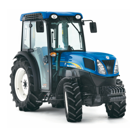
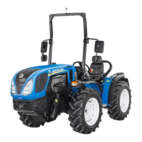
  9. New Holland T4030F User manual

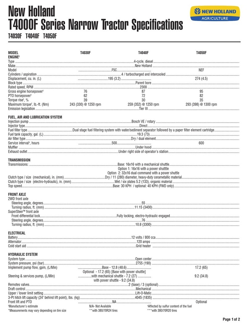
New Holland T4030F User manual

Other manuals for T4030F

2

This manual suits for next models

2

Other New Holland Tractor manuals

New Holland Workmaster 25S User manual

New Holland

New Holland Workmaster 25S User manual

New Holland T3.60F User manual

New Holland

New Holland T3.60F User manual

New Holland T8010 User manual

New Holland

New Holland T8010 User manual

New Holland Boomer 40D CVT User manual

New Holland

New Holland Boomer 40D CVT User manual

New Holland TT45A User manual

New Holland

New Holland TT45A User manual

New Holland Boomer 1020/T1010 User manual

New Holland

New Holland Boomer 1020/T1010 User manual

New Holland T8.275 User manual

New Holland

New Holland T8.275 User manual

New Holland T7.140 User manual

New Holland

New Holland T7.140 User manual

New Holland T9010 User manual

New Holland

New Holland T9010 User manual

New Holland TK65 User manual

New Holland

New Holland TK65 User manual

New Holland TL100A User manual

New Holland

New Holland TL100A User manual

New Holland TL70 Operating instructions

New Holland

New Holland TL70 Operating instructions

New Holland Boomer 30 User manual

New Holland

New Holland Boomer 30 User manual

New Holland Boomer 47 User manual

New Holland

New Holland Boomer 47 User manual

New Holland T6.110 User manual

New Holland

New Holland T6.110 User manual

New Holland TK4020F User manual

New Holland

New Holland TK4020F User manual

New Holland TV6070 User manual

New Holland

New Holland TV6070 User manual

New Holland TI4.70 User manual

New Holland

New Holland TI4.70 User manual

New Holland TS6.110 Tier 3 User manual

New Holland

New Holland TS6.110 Tier 3 User manual

New Holland T4030V User manual

New Holland

New Holland T4030V User manual

New Holland Boomer 40D CVT Tier 3 User manual

New Holland

New Holland Boomer 40D CVT Tier 3 User manual

New Holland T6030 DELTA User manual

New Holland

New Holland T6030 DELTA User manual

New Holland TD65F User manual

New Holland

New Holland TD65F User manual

New Holland Auto Command T7030 User manual

New Holland

New Holland Auto Command T7030 User manual

Popular Tractor manuals by other brands

Capital Automotive Equipment CAEL-245 manual

Capital Automotive Equipment

Capital Automotive Equipment CAEL-245 manual

Kubota MX5200 Operator's manual

Kubota

Kubota MX5200 Operator's manual

Verts Loisirs VLB12597 instruction manual

Verts Loisirs

Verts Loisirs VLB12597 instruction manual

satoh BULL S-630 Instruction book

satoh

satoh BULL S-630 Instruction book

Yard-Man Series 834 owner's manual

Yard-Man

Yard-Man Series 834 owner's manual

Cub Cadet 19A30024100 installation manual

Cub Cadet

Cub Cadet 19A30024100 installation manual

Ariens 936051 Operator's manual

Ariens

Ariens 936051 Operator's manual

MacDon M150 Assembly instructions

MacDon

MacDon M150 Assembly instructions

Toro 03200 Reelmaster 3100-D Operator's manual

Toro

Toro 03200 Reelmaster 3100-D Operator's manual

MASSEY FERGUSON 5400 Series Service manual

MASSEY FERGUSON

MASSEY FERGUSON 5400 Series Service manual

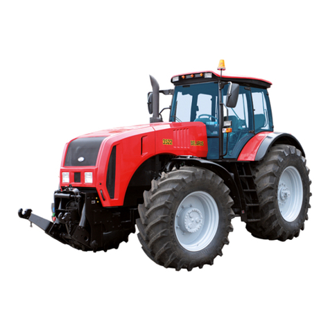
Belarus 3522.5 Operator's manual

Belarus

Belarus 3522.5 Operator's manual

CARRARO Vigneto Operator's manual

CARRARO

CARRARO Vigneto Operator's manual

Cub Cadet 3208 Operator's manual

Cub Cadet

Cub Cadet 3208 Operator's manual

GREMO 1250F Workshop manual

GREMO

GREMO 1250F Workshop manual

HATTAT A90 Service manual

HATTAT

HATTAT A90 Service manual

Kubota WSM STV32 Workshop manual

Kubota

Kubota WSM STV32 Workshop manual

Kubota M108DC Operator's manual

Kubota

Kubota M108DC Operator's manual

AL-KO Heritage RS 14/82 Instruction book

AL-KO

AL-KO Heritage RS 14/82 Instruction book

manuals.online logo
manuals.online logoBrands
  • About & Mission
  • Contact us
  • Privacy Policy
  • Terms and Conditions

Copyright 2025 Manuals.Online. All Rights Reserved.

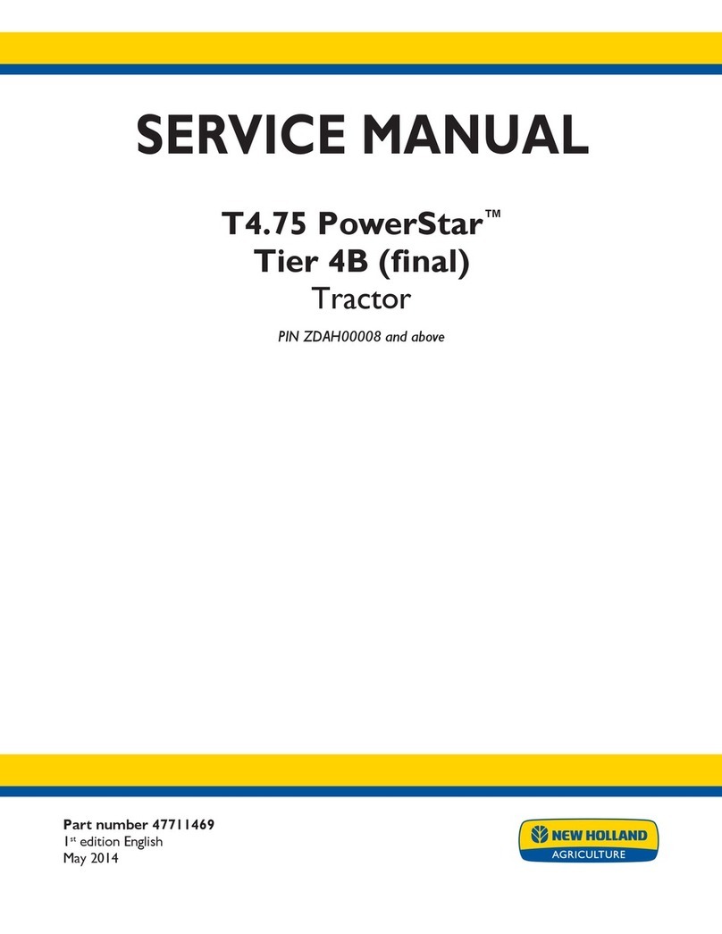
T4030F −T4040F −T4050F TRACTORS
SERVICE MANUAL
SECTIONS
GENERAL GUIDELINES 00. . . . . . . . . . . . . . . . . . . . . . . . . . . . . . . . . . . . . . . . . . . . . . . . . . . . .
ENGINE 10. . . . . . . . . . . . . . . . . . . . . . . . . . . . . . . . . . . . . . . . . . . . . . . . . . . . . . . . . . . . . . . . . . . .
CLUTCH 18. . . . . . . . . . . . . . . . . . . . . . . . . . . . . . . . . . . . . . . . . . . . . . . . . . . . . . . . . . . . . . . . . . . .
TRANSMISSIONS 21. . . . . . . . . . . . . . . . . . . . . . . . . . . . . . . . . . . . . . . . . . . . . . . . . . . . . . . . . . .
DRIVE LINES 23. . . . . . . . . . . . . . . . . . . . . . . . . . . . . . . . . . . . . . . . . . . . . . . . . . . . . . . . . . . . . . .
FRONT MECHANICAL TRANSMISSION 25. . . . . . . . . . . . . . . . . . . . . . . . . . . . . . . . . . . . . . .
REAR MECHANICAL TRANSMISSION 27. . . . . . . . . . . . . . . . . . . . . . . . . . . . . . . . . . . . . . . .
POWER TAKE−OFF 31. . . . . . . . . . . . . . . . . . . . . . . . . . . . . . . . . . . . . . . . . . . . . . . . . . . . . . . . .
BRAKES 33. . . . . . . . . . . . . . . . . . . . . . . . . . . . . . . . . . . . . . . . . . . . . . . . . . . . . . . . . . . . . . . . . . . .
HYDRAULIC SYSTEMS 35. . . . . . . . . . . . . . . . . . . . . . . . . . . . . . . . . . . . . . . . . . . . . . . . . . . . . .
STEERING 41. . . . . . . . . . . . . . . . . . . . . . . . . . . . . . . . . . . . . . . . . . . . . . . . . . . . . . . . . . . . . . . . . .
AXLE AND WHEELS 44. . . . . . . . . . . . . . . . . . . . . . . . . . . . . . . . . . . . . . . . . . . . . . . . . . . . . . . . .
CAB AIR CONDITIONING SYSTEM 50. . . . . . . . . . . . . . . . . . . . . . . . . . . . . . . . . . . . . . . . . . .
ELECTRICAL SYSTEM 55. . . . . . . . . . . . . . . . . . . . . . . . . . . . . . . . . . . . . . . . . . . . . . . . . . . . . . .
PLATFORM, CAB, BODYWORK 90. . . . . . . . . . . . . . . . . . . . . . . . . . . . . . . . . . . . . . . . . . . . . .
T E C H N I C A L S U P P O R T
INTRODUCTION
−This manual is divided into sections identified by two−figure numbers and each section has independent
page numbering.
For easy reference, these sections have the same numbers and names as the Repairs Rate Book sections.
−The different sections can easily be found by consulting the table of contents on the following pages.
−The document number of the manual and the edition/update dates are given at the bottom of each page.
−Pages updated in the future will be identified by the same document number followed by an additional digit:
first edition standard manual 84131814A −1st update 84131814A1 −2nd update 84131814A2 −etc.
The update pages can replace or supplement the pages of the standard manual; the information necessary
for the procedure for adding or replacing pages is given on the title page of the update.
The publication will be completed with an appropriate index.
If it is necessary to issue a new updated manual (2nd edition) it will have document number 84131814B, this
indicates that the manual is composed of the standard version 84131814A completed with all the updates:
1st update 84131814A1 −2nd update 84131814A2 −etc.
−The information contained in this manual was current on the date printed on each section. As
NEW HOLLAND constantly improves its product range, some information may be out of date subsequent
to modifications implemented for technical or commercial reasons, or to meet legal requirements in different
countries.
In the event of conflicting information, consult the NEW HOLLAND Sales and Service Departments.
IMPORTANT WARNINGS
−All maintenance and repair work described in this manual must be performed exclusively by NEW HOLLAND
service technicians, in strict accordance with the instructions given and using any specific tools necessary.
−Anyone performing the operations described herein without strictly following the instructions is personally
responsible for any eventual injury or damage to property.
−The Manufacturer and all organisations belonging to the Manufacturer’s distribution network, including but
not restricted to national, regional or local distributors, will accept no responsibility for personal injury or dam-
age to property caused by abnormal function of parts and/or components not approved by the Manufacturer,
including those used for maintenance and/or repair of the product manufactured or marketed by the Manu-
facturer.
In any case, the product manufactured or marketed by the Manufacturer is covered by no guarantee of any
kind against personal injury or damage to property caused by abnormal function of parts and/or components
not approved by the Manufacturer.
TEXT AND ILLUSTRATIONS ARE THE PROPERTY OF
CNH ITALIA S.P.A.
No part of the text or illustrations
may be reproduced
PRINTED IN ITALY
Print No. 84131814A −06 −2008
INDEX 3
84131814A −06 −2008
CONTENTS VOLUME 1
Page Date
00 −GENERAL GUIDELINES
General instructions . . . . . 1−206−08
Safety regulations . . . . . . . 3−4−506−08
Tractor refuelling . . . . . . . . 6 06−08
10 −ENGINE
CHAPTER 1 −Engine model T4050F
Summary . . . . . . . . . . . . . . 1 06−08
General specifications . .. 2−3−406−08
Fuel system data . . . . . . . . 4 06−08
Engine block data . . . . . 5 06−08
Crankshaft data . . . . . . . . . 5 06−08
Connecting rod data . . . . . 6 06−08
Piston data . . . . . . . . . . . 6−706−08
Timing gear data . . . . . . 7 06−08
Timing gear data −. . . . .
Rotating counterweights
main data . . . . . . . . . . . . . . 7 06−08
Cylinder head data . . . . 8−906−08
Torque specifications . . . . 10−11 06−08
Tools . . . . . . . . . . . . . . . . 12 06−08
Engine view . . . . . . . . . . . . 13 06−08
Lubrication diagrams . . . . 14 06−08
Engine cooling system dia-
gram . . . . . . . . . . . . . . . . . . 15 06−08
Additional counterweight
diagram 16 06−08
Exhaust gas recirculation
system (EGR) . . . . . . . . 17 06−08
Fault diagnosis . . . . . . . . . . 18−19−20−
21 06−08
Engine removal−installa-
tion . . . . . . . . . . 22−23−24−
25−26−27−
28
06−08
Page Date
Engine disassembly−as-
sembly . . . . . . . . . . . . . . . . . 29−30−31−
32−33−34−
35−36−37−
38−39−40−
41−42−43−
44−45−46−
47−48−49−
50−51−52−
53−54−55−
56−57−58−
59−60−61−
62 06−08
Checks and measure-
ments −cylinder block and
liners . . . . . . . . 63−64−65 06−08
Checks and measure-
ments −crankshaft, bear-
ings and flywheel . . . . . . . . 66−67 06−08
Checks and measure-
ments −connecting rods . 68−69 06−08
Checks and measure-
ments −pistons . . . . . . . . . 70−71−72−
73 06−08
Checks and measure-
ments −camshaft, tappets
and valves . . . . . . . . . . . . . 74−75−76−
77 06−08
Checks and measure-
ments −cylinder heads . . 78 06−08
Engine oil low pressure in-
dicator . . . . . . 79 06−08
Engine oil filter . . . . . . . . 79 06−08
Checks and measure-
ments −cooling system . . 80 06−08
Removal−Installation −
crankshaft front seal . . . . . 81−82 06−08
Removal−Installation −
crankshaft rear seal . . . . . 83−84−85 06−08
Valve clearance adjust-
ment . . . . . . . . . . . . . . . . . . . 86−87 06−08
Removal−Installation −in-
jectors 88−89−90 06−08
Removal −Installation −
Bosch injection pump . . . . 91−92−93 06−08
Bosch injection pump −tim-
ing . . . . . . . . . . 94−95−96 06−08
INDEX
4
84131814A −06 −2008
Page Date
Bosch injection pump −air
bleeding . . . . . . . . . . . . . 96 06−08
Removal−Installation −
coolant pump . . . . . . . . . . . 97−98 06−08
Coolant pump drive belts . 99−100 06−08
CHAPTER 2 −Engine models T4030F and
T4040F
Summary . . . . . . . . . . . . . . 1 06−08
General specifications 2−306−08
Engine removal−installa-
tion . . . . . . . . . . 4−5−6−7−8
−9−10 06−08
18 −CLUTCH
Main Data . . . . . . . . . . . . . . 1−206−08
Tightening torque −Tools . 2 06−08
Sections . . . . . . . . . . . . . . . 3−406−08
Fault diagnosis . . . . . . . . . . 5 06−08
Removal−Installa-
tion −clutch 606−08
Clutch Overhaul . . . . . . . 7−8−9−10−
11 06−08
Checks and measure-
ments −clutch . . . . . . . . . . 12−13 06−08
Adjustments −clutch disen-
gagement levers . . . . . . . . 13−14 06−08
Adjustments −clutch pedal 15 06−08
PTO clutch lever adjust-
ment . . . . . . . . . 16 06−08
PTO clutch servo control
Sections . . . . . . . . . . . . . . . 17 06−08
Description and operation 18−19 06−08
Servo control adjustment . 20 06−08
21 −TRANSMISSION
CHAPTER 1 −Transmission and range gear
(16x16)
Main Data . . . . . . . . . . . . . . 1−206−08
Torque specifications . . . . 2−306−08
Page Date
Tools . . . . . . . . . . . . . . . . 4−506−08
Sections . . . . . . . . . . . . . . . 6−7−8−9−
10 06−08
Description and operation 11 06−08
Fault diagnosis . . . . . . . . . . 11−12 06−08
Removal−Installation −
rear transmission −gear-
box casing . . . . . . . . . . . . . 13−14−15−
16−17−18−
19−20−21−
22−23−24 06−08
Disassembly−Assembly −
transmission−gearbox cas-
ing . . . . . . . . . . . . . . . . . . . . 25−26−27−
28−29−30−
31−32 06−08
Gearbox driving and driven
shafts end float adjustment. 33 06−08
Sealing compound applica-
tion diagram . . . . . . . . . . . . 34 06−08
CHAPTER 2 −Mechanical transmission and
splitter
Main Data . . . . . . . . . . . . . . 1−206−08
Torque specifications . . . . 2 06−08
Tools . . . . . . . . . . . . . . . . 2 06−08
Sections . . . . . . . . . . . . . . . 3−4−506−08
Description and operation 6 06−08
Fault diagnosis . . . . . . . . . . 7 06−08
Splitter device and creeper
unit casing, shafts and
bearings disassembly . . . . 8−9−10 06−08
CHAPTER 3 −Power Shuttle transmission
Main Data . . . . . . . . . . . . . . 1−206−08
Torque specifications . . . . 3 06−08
Tools . . . . . . . . . . . . . . . . 4−506−08
Sections . . . . . . . . . . . . . . . 6−7−8−9−
10 06−08
INDEX 5
84131813A −06 −2008
Page Date
Clutch control pressure test 9 06−08
Description and operation 11 06−08
Fault diagnosis . . . . . . . . . . 11 06−08
Disassembly−Assembly −
transmission−gearbox cas-
ing . . . . . . . . . . . . . . . . . . . . 12−13−14−
15−16−17−
18 06−08
Disassembly−Reassembly
−Power Shuttle control
valve . 19−20−21 06−08
Disassembly−Assembly −
accumulator . . . . . . . . . . . . 22 06−08
23 −DRIVE LINES
Main Data . . . . . . . . . . . . . . 1 06−08
Torque specifications . . . . 2 06−08
Sections . . . . . . . . . . . . . . . 3−406−08
Description and operation 5−606−08
Fault diagnosis . . . . . . . . . . 6 06−08
Removal−Installation −
drive gear casing . . . . . . . . 7−8−906−08
Disassembly−Assembly −
drive gear casing . . . . . . . . 10−11 06−08
25 −MECHANICAL TRANSMISSION
FRONT
Main Data . . . . . . . . . . . . . . 1−206−08
Torque specifications . . . . 3−4−506−08
Tools . . . . . . . . . . . . . . . . 6 06−08
Sections . . . . . . . . . . . . . . . 7−8−9−10−
11 06−08
Description and operation 11−12 06−08
Fault diagnosis . . . . . . . . . . 13 06−08
Removal−Installation −
front axle . . . . . . . . . . . . . . . 14−15−16−
17−18−19−
20−21 06−08
Page Date
Disassembly−Assembly −
front epicyclic final drive
with brake . . . . . . . . . . . . . . 22−23 06−08
Disassembly−Assembly −
front epicyclic final drive . . 24−25−26 06−08
Disassembly−Assembly −
wheel hubs and steering
knuckle 27 06−08
Adjustments −steering
knuckle bearings . . . . . . . . 28 06−08
Removal−Installation −
front axle differential and
bevel drive support . . . . . . 29−30−31−
32 06−08
Overhaul −differential lock
unit . . . . . . . . . . . . . . . . . . 33−34−35 06−08
Overhaul −front axle bevel
drive . . . . . . . . . . . . . . . . . 36−37 06−08
Adjustments −bevel drive 38−39−40−
41−42−43−
44 06−08
Overhaul −front differential 45 06−08
Replacing steering knuckle
pins and bearings . . . . . . . 46 06−08
27 −MECHANICAL TRANSMISSION
REAR
Main Data . . . . . . . . . . . . . . 1−206−08
Torque specifications . . . . 3−406−08
Tools . . . . . . . . . . . . . . . . 5−6−706−08
Sections . . . . . . . . . . . . . . . 8−906−08
Description and operation 9−10 06−08
Fault diagnosis . . . . . . . . . . 11−12 06−08
Disassembly−Assembly −
transmission−gearbox cas-
ing . . . . . . . . . . . . . . . . . . . . 13−14−15−
16−17−18 06−08
Adjustments −differential
lock engagement sleeve
position . . . . . . 19 06−08
Adjustments −bevel drive 20−21−22−
23−24 06−08
Removal −Installation
side gear casing . . . . . . . . 25−26−27 06−08
INDEX
6
84131814A −06 −2008
Page Date
Disassembly−Assembly −
drive wheel shaft . . . . . . . . 27−28−29 06−08
Disassembly−Assembly −
epicyclic final drive . . . . . . 29 06−08
31 −POWER TAKE−OFF
CHAPTER 1 −Mechanical power take−off
Main Data . . . . . . . . . . . . . . 1−2−306−08
Tools . . . . . . . . . . . . . . . . 3 06−08
Torque specifications . . . . 4−506−08
Sections . . . . . . . . . . . . . . . 6−706−08
Description and operation 8−9−10 06−08
Fault diagnosis . . . . . . . . . . 10 06−08
Power take−off overhaul . 11−12−13−
14 06−08
33 −BRAKES
Main Data . . . . . . . . . . . . . . 1−206−08
Torque specifications . . . . 2 06−08
Sections . . . . . . . . . . . . . . . 3−4−506−08
Tools . . . . . . . . . . . . . . . . 5−606−08
Description and operation 6 06−08
Fault diagnosis . . . . . . . . . . 7−806−08
Removal−Installation−ser-
vice brake . . . . . . . . . . . . . . 9−10 06−08
Removal−Installation−ser-
vice brake pump . . . . . . . . 11−12−13−
14 06−08
Adjustments −service
brake pedals travel . . . . 14−15 06−08
Service brake circuit air
bleeding . . . . . . . . . . . . . . . 15−16−17 06−08
Removal−Installation −
parking brake . . . . . . . . . . . 17−18 06−08
Adjustments −parking
handbrake travel . . . . . . . . 19 06−08
35 −HYDRAULIC SYSTEMS
CHAPTER 1 −Rear mechanical hydraulic lift
Main Data . . . . . . . . . . . . . . 1−2−306−08
Page Date
Torque specifications . . . . 3−406−08
Tools . . . . . . . . . . . . . . . . 5 06−08
Sections . . . . . . . . . . . . . . . 6−7−8−9−
10 06−08
Description and operation 11−12−13−
14 06−08
Fault diagnosis . . . . . . . . . . 15−16 06−08
Removal−Installation −lift 17−18−19 06−08
Disassembly−Assembly −
lift . . . . . . . . . . . . . . . . . . . 20−21−22−
23−24−25 06−08
Adjusting the lift 26−27−28−
29−30−31−
32−33−34−
35 06−08
Lift pressure relief valve . . 36 06−08
Disassembly−Assembly −
lift control valve . . . . . . . 37−38−39−
40 06−08
CHAPTER 2 −Auxiliary control valves
Open centre system
Main Data . . . . . . . . . . . . . . 1 06−08
Tools . . . . . . . . . . . . . . . . 1 06−08
Torque specifications . . . . 2 06−08
Sections . . . . . . . . . . . . . . . 3−4−506−08
Description and operation 6−7−8−906−08
Removal−Installation −
front auxiliary control
valves . . . . . . . 10−11−12 06−08
Disassembly−Assembly −
auxiliary control valves . . . 13−14 06−08
Rod hardening test . . . . . . 14 06−08
Blow−by test . . . . . . . . . . 15 06−08
Adjustment of the automat-
ic detent release pressure 15 06−08
Removal−Installation −
flow control valve . . . . . . . . 16 06−08
Flow control valve adjust-
ment . . . . . . . . . 17−18 06−08
INDEX 7
84131813A −06 −2008
Page Date
CHAPTER 3 −Auxiliary control valve
for trailer braking
Sections . . . . . . . . . . . . . . . 1 06−08
Description and operation 1−2−3−4−5
−6−706−08
Fault diagnosis . . . . . . . . . . 8−9−10 06−08
Removal−Installation −
trailer brake valve . . . . . . . 11 06−08
CHAPTER 4 −Electronically controlled hy-
draulic lift
Main Data . . . . . . . . . . . . . . 2−306−08
Torque specifications . . . . 4 06−08
Tools . . . . . . . . . . . . . . . . 5 06−08
Sections . . . . . . . . . . . . . . . 6−7−806−08
Location of Components . 9−10 06−08
Description and operation 11−12−13−
14−15−16−
17 06−08
Removal−Installation −lift 18−19−20−
21−22 06−08
Replacement −control unit 23 06−08
Position sensor replace-
ment . . . . . . . . . . . . . . . . . 24−25 06−08
Replacement −draft
sensor . . . . . . . . . . . . . . . 26 06−08
Disassembly−Assembly −
lift . . . . . . . . . . . . . . . . . . . 27−28 06−08
Cylinder safety valve . . . . . 31 06−08
Removal−Installation −hy-
draulic control valve . . . . . 32−33 06−08
Disassembly−Assembly −
hydraulic control valve . .. 33−34−35 06−08
CHAPTER 5 −Constant flow gear pump
Main Data . . . . . . . . . . . . . . 1−206−08
Torque specifications . . . . 2 06−08
Description and operation 2 06−08
Page Date
Diagrams . . . . . . . . . . . . . . 3 06−08
Disassembly−Reassembly
−gear pumps . . . . . . . . . 4 06−08
41 −STEERING
CHAPTER 1 −Steering
Main Data . . . . . . . . . . . . . . 2 06−08
Torque specifications . . . . 2 06−08
Tools . . . . . . . . . . . . . . . . 2 06−08
Description and operation 3−4−506−08
View of hydrostatic steering
control valve components 6 06−08
Fault diagnosis . . . . . . . . . . 7−806−08
Removal−Installation −
steering wheel 9 06−08
Removal−Installation −hy-
drostatic steering control
valve . . . . . . . . 10−11−12 06−08
Disassembly−Assembly −
hydrostatic control valve . . 13−14−15−
16−17−18−
19−20−21−
22−23−24−
25−26−27−
28 06−08
Hydrostatic steering control
valve bench testing . . . . . . 29−30 06−08
Pressure relief valve testing 31 06−08
CHAPTER 2 −Constant flow gear pump
Main Data . . . . . . . . . . . . . . 1−206−08
Torque specifications . . . . 2 06−08
Diagrams . . . . . . . . . . . . . . 3−406−08
Description and operation 4 06−08
Disassembly−Reassembly
−gear pumps . . . . . . . . . 5 06−08
44 −AXLES AND WHEELS
Main Data . . . . . . . . . . . . . . 1−206−08
Front wheel track diagram 2 06−08
Sections . . . . . . . . . . . . . . . 3 06−08
Torque specifications . . . . 4−5−606−08
Tools . . . . . . . . . . . . . . . . 6−706−08
INDEX
8
84131814A −06 −2008
Page Date
Fault diagnosis . . . . . . . . . . 7 06−08
Removal−Installation −
front axle . . . . . . . . . . . . . . . 8−9−10 06−08
Disassembly−Assembly −
wheel axle hub . . . . . . . . 11−12−13 06−08
Stub axle hub overhaul . . . 14−15−16−
17 06−08
Checking leading wheel
alignment . . . . . . . . . . . . . . 18 06−08
50 −CAB AIR CONDITIONING SYSTEM
Safety regulations . . . . . . . 2 06−08
Main specifications . . . . . . 3 06−08
Tools . . . . . . . . . . . . . . . . 4 06−08
Operating principles . .. 5 06−08
Conditioning system com-
ponents . . . . . . 6−7−8−9−
10−11 06−08
Cab controls . . . . . . . . . . 12−13−14 06−08
Instructions for use −air
conditioning system . . . . . 15 06−08
Refrigerant recovery −re-
cycling and evacuation −
charging stations . . . . . . . . 16−17 06−08
Dehydration, recharging
and refrigeration check . .. 18−19−20−
21−22 06−08
System recharging function
check . . . . . . . . . . . . . . . . 23−24−25−
26−27−28 06−08
Fault diagnosis . . . . . . . . . . 29−30−31−
32 06−08
Air conditioning system
maintenance . . . . . . . . . . 33 06−08
Compressor drive belt ten-
sion adjustment . . . . . . . . . 34 06−08
Removal−Installation −air
conditioning unit . . . . . . . . . 35−36−37−
38 06−08
55 −ELECTRICAL SYSTEM
CHAPTER 1 −Instruments
Analogue instrumentation 1−2−3−406−08
Electronic Instruments . 5−6−7−8−906−08
Page Date
Transmitters, sensors and
switches . . . . . . . . . . . . . . . 10−11−12−
13−14−15−
16−17 06−08
CHAPTER 2 −Components
Components . . . . . . . . . . . . 2−3−4−5−6
−70
6−08
Service . . . . . . . . . . . . . . 8−9−10−11 06−08
CHAPTER 3 −Starting System
Technical data . . . . . . . . . . 1 06−08
Description and operation 2 06−08
Fault diagnosis . . . . . . . . . . 3 06−08
System testing . . . . . . . . . . 4−5−606−08
Overhaul . . . . . . . . . . . . . . . 7−806−08
Starter motor testing . . . . . 9−10 06−08
CHAPTER 4 −Charging system
Technical data . . . . . . . . . . 1 06−08
Torque specifications . . . . 1 06−08
Description and operation 2−306−08
System testing . . . . . . . . . . 4−5−6−7−8
−9−10 06−08
Removal−Installation and
Overhaul −alternator . . . . 11−12−13−
14−15−16−
17−18 06−08
CHAPTER 5 −Battery
Technical data . . . . . . . . . . 1 06−08
Description and operation 1 06−08
Removal−Installation−bat-
tery . .. 206−08
Battery maintenance . . . . . 3 06−08
Battery charging . . . . . . . . 4−5−606−08
Battery troubleshooting . . 7 06−08
CHAPTER 6 −Electrical circuits for tractors
with cab
Index . . . . . . . . . . . . . . . . . . 1 06−08
INDEX 9
84131813A −06 −2008
Page Date
CHAPTER 7 −Electrical circuits for tractors
with platform
Index . . . . . . . . . . . . . . . . . . 1 06−08
CHAPTER 8 −Connectors
Index . . . . . . . . . . . . . . . . . . 1 06−08
CHAPTER 9 −Error codes
Index . . . . . . . . . . . . . . . . . . 1 06−08
CHAPTER 10 −HH Menu and calibrations
Index . . . . . . . . . . . . . . . . . . 1 06−08
90 −BODYWORK AND DRIVING POSITION
CHAPTER 1 −Cab removal−installation
Removal−Installation −cab 1−2−3−4−5
−6−7−806−08
CHAPTER 2 −Removal of cab internal com-
ponents
Multi−function panel Re-
moval−Installation . . . . . . . 1 06−08
Fuse or relay replacement 2 06−08
Fusebox replacement . . . . 3 06−08
Removal−Installation −
electronic control unit . . . . 4−5−606−08
Removal−Installation wind-
screen wiper motor . . . . . . 7 06−08
Removal−Installation rear
windscreen wiper motor . . 8 06−08
Replacement of glued cab
windows . . . . . . . . . . . . . . . 9−10 06−08
INDEX
10
84131814A −06 −2008