Power Tec AF1045 User manual

Owner’s Manual
Model No. AF1045
You will need this manual for safety instructions, operating procedures, and warranty.
Put it and the original sales invoice in a safe, dry place for future reference.
20-0805
Visit us on the web at powertecproducts.com
QUESTION...
1•847•780•6120
REMOTE CONTROLLED 3-SPEED
AIR FILTRATION SYSTEM

PRODUCT
SPECIFICATIONS
Controls................... Manual or Remote Control
Remote Control Distance ........... 65 feet (20 meters)
Number of Speeds ...............................3
Motor Speeds (RPM) ...................750/960/1200
Air Flow (CFM) ........................655/875/1060
Outer Filter ...............................5 Micron
Inner Filter ................................1 Micron
Filtration Timing.............Auto Off, 1 HR, 2 HR, 4HR
Net Weight ...........................62 lbs. (28 kg)
Gross weight ........................69 lbs (31.5 kg)
Sound Rating @ 3 Feet .............Hight Speed 68dB
. . . . . . . . . . . . . . . . . . . . . . . . . . . . . . .Medium Speed 67dB
. . . . . . . . . . . . . . . . . . . . . . . . . . . . . . . . . Low Speed 63 dB
MOTOR
SPECIFICATIONS
This air filtration system is supplied with a 1/5 HP motor
installed. The 120 Volt AC universal motor has the
following specifications:
Motor Amperage ................................3A
Voltage ......................................120
Hertz. . . . . . . . . . . . . . . . . . . . . . . . . . . . . . . . . . . . . . . ...60
RPM............................... 750/960/1200
TABLE OF CONTENTS
SAFETY RULES 1
ASSEMBLY 2
Unpacking
Installation
Power Source
Grounding Instructions
Extension Cords
OPERATIONS 6
ON/SPEED Control
Filtration Timing
To Turn the Unit OFF
MAINTENANCE 7
Changing the Filters
Remote Control Battery Replacement
To Replace the Fuse
TROUBLESHOOTING 8
PARTS ILLUSTRATION 10
& LIST
WARRANTY 12
SECTION PAGE

GENERAL SAFETY RULES 1
WARNING
For your own safety, read and understand all warnings
and operating instructions before using any tool
or equipment.
WARNING
Some dust created by operation of power tool contains
chemicals known to the State of California to cause
cancer, birth defects or other reproductive harm. To
reduce your exposure to these chemicals, work in a well
ventilated area and work with approved safety equipment.
Always wear OSHA/NIOSH approved, properly fitting face
mask or respirator when using such tools.
WARNING
Failure to follow these rules may result in serious personal
injury. Remember that being careless for even a fraction
of a second can result in severe personal injury.
WORK PREPARATION
• Wear proper apparel. Do not wear loose clothing,
gloves, neckties, rings, bracelets or other jewelry which
may get caught in moving parts of the tool.
• Nonslip protective footwear is recommended. Wear
protective hair covering to contain long hair.
• Wear eye and hearing protection. Always use safety
glasses. Eye protection equipment should comply with
ANSI Z87.1 standards. Hearing equipment should
comply with ANSI S3.19 standards.
• Wear face mask or dust mask if operation is dusty.
• Be alert and think clearly. Never operate power tools
when tired, intoxicated or when taking medications that
cause drowsiness.
WORK AREA PREPARATION
• Keep work area clean. Cluttered work areas and
benches invite accidents.
• Work area should be properly lit.
• Do not use the machine in a dangerous environment.
The use of power tools in damp or wet locations or in
rain can cause shock or electrocution.
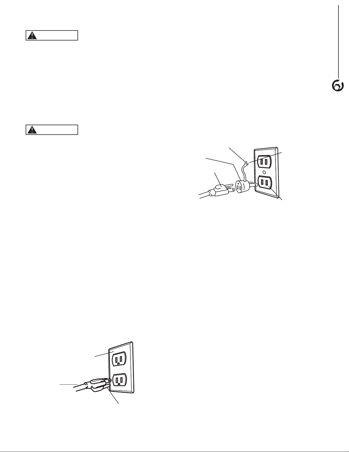
• Three-prong plug should be plugged directly into
properly grounded, three-prong receptacle.
• Use the proper extension cord. Make sure your
extension cord is in good condition. It should have
grounding prong and should be of the correct gauge.
• Keep children and visitors away. Your shop is a
potentially dangerous environment. Children and visitors
can be injured.
• Make your workshop childproof with padlocks, master
switches or remove switch keys to prevent any
unintentional use of power tools.
1
SAFETY RULES
TOOL MAINTENANCE
• Turn the machine "OFF", and disconnect the machine
from the power source prior to inspection.
• Maintain all tools and machines in peak condition. Keep
tools sharp and clean for best and safest performance.
• Follow instructions for lubricating and changing
accessories.
• Check for damaged parts. Check for alignment of
moving parts, binding, breakage, mounting and any
other condition that may affect tool's operation.
• Poorly maintained tools and machines can further
damage the tool or machine and/or cause injury.
• A guard or any other part that is damaged should be
repaired or replaced. Do not perform makeshift repairs.
TOOL OPERATION
• Avoid accidental start-up. Make sure that the tool is in
the “OFF” position before plugging in.
• Use the right tool for your job. Do not force your tool or
attachment to do a job for which it was not designed.
• Disconnect tool when changing parts.
• Don't force the workpiece on the machine. Damage to
the machine and/or injury may result.
• Never leave tool running unattended. Turn the power off
and do not leave tool until it comes to a complete stop.
• Do not overreach. Loss of balance can make you fall
into a working machine, causing injury.
• Never stand on tool. Injury could occur if the tool tips, or
if you accidentally contact the cutting tool.
• Know your tool. Learn the tool’s operation, application
and specific limitations before using it.
• Use a proper extension cord of the correct gauge. Your
extension cord should have a grounding prong, and
should be in good condition.
• Handle workpiece correctly. Keep hands away from
moving parts.
• Turn tool off if it jams.
• Always feed workpiece against the direction of the
sanding rotation. To maintain control, properly support
long or wide work-pieces.
CAUTION
Think safety! Safety is a combination of operator common
sense and alertness at all times when tool is being used.
WARNING
Do not attempt to operate tool until it is completely
assembled according to the instructions.
SAVE ALL WARNINGS AND INSTRUCTIONS
FOR FUTURE REFERENCE

SPECIFIC SAFETY RULES FOR AIR FILTRATION SYSTEM
2
Be aware of general power tool safety. Make sure all the
safety rules are understood.
• Disconnect the machine from power source whenever
adjusting or replacing any parts.
• Do not plug air filtration system in unless switch is in the
“OFF” position.
• Keep hands away from all moving parts.
• Wear eye protection or face shield during operation.
• Make sure all mobile parts move freely and are free
from interference.
• If ceiling mounted, bottom of air filtration system must
be at least 7 feet above the floor.
• If ceiling mounted, mounts must be anchored to building
structure which will support a minimum of at least
100 pounds. Never mount to surfaces such as dry wall
or false ceiling grinds, etc.
ASSEMBLY
UNPACKING
Refer to Figure 1
The air filtration system is shipped assembled and
requires minimum assembly and installation.
• Examine shipping carton for freight damage before
opening. If shipping carton is damaged file a claim with
the carrier immediately.
• Carefully remove all contents from shipping carton. The
shipping carton contains:
1 - Air Filtration System (with 5-Micron pleated-type
outer filter and 1-Micron bag-type inner filter)
1 - Remote Control (with two AA batteries)
4 - Mounting Brackets
8 - 3 in 1 M6 Bolts (include bolt, flat washer and lock
washer) (mounting bracket assembly)
4 - M6 Eye Bolts
4 - Flange Nuts (eye bolt assembly)
4 - Rubber Feet
4 - Double Sided Tape (Rubber Feet Assembly)
1 - Owner's Manual (not shown)
NOTE: Contact the customer service center if any of these
parts are missing.
NOTE: After unit is assembled dispose of all packaging
material in an environmentally safe way.
Air Filtration
System
Remote Control
3 in 1 M6 Bolts (8)
Eye Bolt (4)
Mounting Brackets (4)
Figure 1
2
ASSEMBLY SPECIFIC SAFETY RULES
2
2
• To reduce the risk of electrical shock, do not expose air
filtration to water or rain.
• Never duct a machine directly into the air
filtration system.
• Do not use air filtration system without filters in place.
• To avoid a potentially dangerous situation, do
not use this machine to filter flammable vapors or
smoke. This air filtration system is designed and
intended for the filtration of air borne wood dust only.
It is neither designed nor intended for any other
purpose whatsoever.
• Use the machine for filtering wood dust only. Not for
use filtering sheet rock dust, silica, lead paint dust,
asbestos, bio-hazards, smoke, toxic fumes, spray paint
or flammable liquids.
• Failure to follow these rules may result in serious
personal injury/or property damage.
Rubber Feet (4)
Double Stick Tape (4)
CAUTION
The air filtration system is too heavy to be lifted by one
person. Obtain assistance from others before trying to lift
or move.
Flange Nuts (4)

INSTALLATION
Refer to Figure 1 to 8
This air filtration system is specifically designed to circulate
and filter non-metallic dust, which is generated throughout
the work area. The unit can be located on a work bench,
hung from an overhead support or mounted to the ceiling
or wall. When selecting a location ensure the power
source is easy to access. Ensure the remote control is
within 65 feet of the control panel with no obstructions.
IMPORTANT: When determining a location for the air
filtration system, always select a location where the air
flow is unrestricted. Locate the unit away from corners and
any heating or cooling vents.
CAUTION
The air filtration system is too heavy to be lifted by one
person. Obtain assistance from others before trying to lift
or move.
Remove the Shipping Blocks
Refer to Figures 2 -3
Styrofoam shipping blocks are installed around the motor
to prevent damage during shipping. These MUST be
removed before operation.
• Lift up on the clips located at the top and bottom of the
cabinet and remove the outer filter.
• Pull the inner filter from the cabinet.
• Remove the four Phillips head screws securing the inner
grate and remove the inner grate.
• Remove the shipping blocks and replace the inner grate.
Figure 2
Inner Grate
ScrewsScrews
Figure 3 Shipping
Block
Shipping
Block
ASSEMBLY
3
• Follow the instructions under Changing the Filters to
replace the filters correctly.
Work Bench Location
Tools required for assembly: None
CAUTION
Clamp the air filtration system in place if using on a work
bench or sawhorse, if not permanently mounting the unit.
• With assistance, carefully turn the air filtration
system over.
• Use the double sided tape to attach the four rubber feet
to the four bottom corners of the unit. (Figure 4)
• With assistance, carefully turn the air filtration
system over.
• Place the air filtration system onto a work bench, ensure
the air flow is not restricted and the unit is away from
corners and any heating or cooling vents.
• Plug the power cord into the correct receptacle.
(Refer to Power Source paragraph in this section of
the manual.)
Figure 4
Rubber Feet
Rubber Feet

Hanging Mount
Tools required for assembly:
No. 2 Phillips screwdriver (not supplied)
10 mm wrench (not supplied)
NOTE: Hang the unit at least 7 Feet above floor level and
away from corners and any heating or cooling vents.
• Remove four screws from the cabinet top (Figure 5).
NOTE: Save the four screws for future use. These
screws will be needed to seal the holes in the cabinet
top if the eye bolts are removed.
Figure 5
Screw
• Thread a flange bolt almost all the way up onto each
eye bolt. (Figure 6)
• Thread the eye bolt into the hole on the cabinet top.
Tighten the eye bolt and flange nut against the top of
the cabinet.
• Repeat for remaining three eye bolts.
Figure 6 Eye Bolt
Flange Nut
CAUTION
Mounting hooks must be anchored to a building
structure which can support a minimum of 100
pounds. Never mount to surface such as dry wall or
false ceiling grids, etc.
• Anchor the four chain, cable or steel strapping lines (not
supplied) into the buildings ceiling joist. Never mount to
surface such as dry wall or false ceiling grids, etc.
• Attach a chain (not supplied) to each hanging eye bolt.
NOTE: When the chains hang down freely they should
be 15-1/4" from left to right and 24-1/2" from front
to rear.
• With assistance raise and secure the air filtration system
eye bolts to the four hanging lines (Figure 7).
Anchor
(not supplied)
Chain, Cable or
Steel Strapping
Lines
(not supplied)
Eye Bolt
Figure 7
• Ensure the unit is level horizontally. Adjust if needed.
• Plug the power cord into the correct receptacle. (Refer
to Power Source paragraph in this section of the
manual.)
Flush Mounting
CAUTION
Mounting hardware must be anchored to a building
structure which can support a minimum of 100
pounds. Never mount to surface such as dry wall or
false ceiling grids, etc.
• Mark the air filtration system bolt pattern on the mounting
surface. NOTE: Bolt pattern should be 17-1/4" from left
to right and 31" from front to rear.
• Drill holes in the mounting surface at the marks.
• Mounting bracket holes are found on each side of the
unit, slide the mounting brackets under the cover lip and
secure the mounting brackets to the unit with the 3 in 1
M6 Bolts (with flat washer and lock washer). Tighten all
bolts. (Figure 8)
Figure 8
Mounting
Brackets
Hex Bolt
Flat Washer
Lock Washer
• With assistance, carefully lift the air filtration system in
place aligning drilled holes to mounting brackets. Bolt the
air filtration system in place.
NOTE: Use 1/4" shank lag bolts for studs or 1⁄4" nuts,
bolts, and washers for mounting to supports.
4
ASSEMBLY

POWER SOURCE
WARNING
Do not connect to the power source until the machine is
completely assembled.
The machine is wired for 120 volts, 60 HZ alternating
current. Before connecting the machine to the power
source, make sure the switch is in the “OFF” position.
Running the unit on voltages which are not within range
may cause overheating and motor burn-out. Heavy loads
require that voltage at motor terminals be no less than the
voltage specified on nameplate.
GROUNDING INSTRUCTIONS
WARNING
Improper connection of equipment grounding conductor
can result in the risk of electrical shock.
• The machine should be grounded while in use to protect
operator from electrical shock.
• In the event of an electrical short circuit, grounding
reduces the risk of electrical shock by providing an
escape wire for the electric current.
• This machine is equipped with an approved 3-conductor
cord rated at 120V and a 3-prong grounding type plug
for your protection against shock hazards.
• Grounding plug should be plugged directly into a
properly installed and grounded 3-prong grounding-type
receptacle, as shown (Figure 9).
• The plug must be plugged into an outlet that is properly
installed and grounded in accordance with all local
codes and ordinances.
• Check with a qualified electrician or service personnel if
these instructions are not completely understood or if in
doubt as to whether the tool is properly grounded.
• Do not modify plug provided. If it will not fit in outlet,
Have a proper outlet installed by a qualified electrician.
Use only 3-wire extension cords, that have 3-prong
grounding type plugs and matching 3-conductor
receptacles that accept the machine’s plug, as shown in
Figure 9.
Figure 9 - 3-Prong Receptacle
Grounded Outlet Box
3 - Prong Plug
Grounded
Prong
Do not permit fingers to touch the terminals of plug when
installing or removing from outlet.
• Inspect tool cords periodically, and if damaged, have it
repaired by an authorized service facility.
• The conductor with insulation having an outer surface
that is green with or without yellow stripes is the
equipment-grounding conductor. If repair or replacement
of the electric cord or plug is necessary, do not connect
the green (or green and yellow) wire to a live terminal.
• A temporary 3-prong to 2-prong grounding adapter
(see Figure 10) may be used to connect this plug to a
matching 2-conductor receptacle as shown in Figure 10.
The temporary adapter should be used only until
a properly grounded outlet can be installed by a
qualified electrician.
Figure 10 - 2-Prong Receptacle
Grounded Lug
Adapter
2-Prong Plug
Make Sure This
is Connected to a
Known Ground
2-Prong Receptacle
In Canada, the use of temporary adapter is not permitted
by the Canadian Electric Code. Where permitted, the rigid
green tab or terminal on the side of the adapter must be
securely connected to a permanent electrical ground such
as a properly grounded water pipe, a properly grounded
outlet box or a properly grounded wire system.
• Many cover plate screws, water pipes and outlet boxes
are not properly grounded. To ensure proper grounding
means that it must be tested by a qualified electrician.
EXTENSION CORDS
Use proper extension cords. Make sure the extension
cord is in good condition. Use only 3-wire extension
cords that have 3-prong grounding type plugs and 3-pole
receptacles which accept the tool plug. When using an
extension cord, make sure to use one heavy enough to
carry the current of the machine. An undersized cord will
cause a drop in the voltage, resulting in loss of power and
overheating. Use the table to determine the minimum wire
size (A.W.G.) extension cord.
Extension Cord Length
Wire Size……………. ........................ A.W.G.
Up to 100 ft…………… ....................16 gauge
NOTE: Using extension cords over 100 ft. long is
not recommended.
ASSEMBLY
5

OPERATION
6
Refer to Figure 11, 12
This air filtration system can be controlled using the
remote control (Figure 11) or the control panel (Figure 12)
located at the rear of the unit.
NOTE: The filtration timing can ONLY be controlled with
the remote.
ON/SPEED CONTROL
Press the ON/SPEED button on the remote control or the
control panel.
The ON/SPEED button controls the SPEED setting. The
LOW, MID or HI LED light will illuminate to indicate the
selected speed.
• Press the ON/SPEED button once for LOW speed. The
LOW LED light on the control panel will illuminate.
• Press the ON/SPEED button twice for MID speed.
The MID LED light will illuminate to indicate the
selected speed.
• Press the ON/SPEED button three times for HI
speed. The HI LED light will illuminate to indicate the
selected speed.
FILTRATION TIMING
NOTE: The filtration timing can ONLY be controlled with
the remote.
The TIMER button controls the timer setting. The 1
HR, 2 HR and 4HR LED lights on the control panel will
illuminate to show the filtration timing length.
• Press the TIMER button once and the 1HR LED light
will illuminate. The machine will operate for 1 hour then
turn off.
• Press the TIMER button twice and the 2HR LED light
will illuminate. The machine will operate for 2 hours then
turn off.
• Press the TIMER button three times and the 4HR LED
light will illuminate. The machine will operate for 4 hours
then turn off.
NOTE: If no filtration timing LED light is illuminated the air
filtration system will operate until the unit is turned off.
TO TURN THE UNIT OFF
Press the OFF button on the remote control or the control
panel to turn the unit off.
Figure 11
Figure 12
OPERATION
6

WARNING
Disconnect the machine from power source whenever
adjusting or replacing any parts.
CHANGING THE FILTERS
Refer to Figure 13
The inner and outer filters should be replaced and / or
cleaned depending on the amount of usage and the
environment of your workshop. Clogged filters will reduce
the amount of air circulation.
• Lift up on the clips located at the top and bottom of the
cabinet and remove the outer filter.
• Pull the inner filter from the cabinet. The inner filter can
be shaken out or washed to extend its life. The filter
should be completely dry before reinstalling into the unit.
NOTE: Do not use compressed air to blow out the
inner filter. The high pressure will damage the filter and
reduce filtering quality.
• Insert the new or cleaned inner filter and then install
the new outer filter. The arrow on the outer filter
indicates the air flow direction, ensure the filter is
positioned properly.
Figure 13
Clip
Inner
Outer
Arrow
REMOTE CONTROL BATTERY
REPLACEMENT
• Remove the battery compartment cover on the
remote control.
• Replace the batteries. Ensure the batteries are
oriented as shown inside the battery compartment. Use
AA batteries.
• Replace the battery compartment cover.
NOTE: When disposing batteries, think of the protection of
the environment. Check with your local authorities for an
environmentally safe way of battery disposal.
CHECKING AND REPLACING THE FUSE
Refer to Figure 14
If the unit overloads, the line inside the fuse will break to
cut the circuit and protect the unit.
To Replace the Fuse
1. Turn the fuse cap counterclockwise and pull the fuse out of
the control panel.
2. If damaged, replace the fuse (Part No. 1045-009, 4 Amps).
Place the new fuse into the fuse cap and insert it into
position. Tighten the fuse cap.
Figure 14
Fuse
Fuse Cap
MAINTENANCE
7
MAINTENANCE 7

5
TROUBLESHOOTING 8
SYMPTOM POSSIBLE CAUSE(S) CORRECTIVE ACTION
Motor does not run 1. Machine not plugged in 1. Plug power cord into electrical receptacle
2. ON/SPEED button is in "OFF" position 2. Press the ON/SPEED button to turn unit on
3. Power switch or cord is faulty 3. Replace switch or power cord
4. Blown fuse 4. Overloaded electrical circuit
5. Remote control is not working 5. Point remote control directly at control panel
- Make sure remote sensor on the control panel is not
blocked
- Move remote control closer to the control panel for better
direct signal
6. Remote control batteries are dead 6. Replace batteries. See Remote Control Battery
Replacement for instruction
7. Receiver is not working 7. Inspect or replace control panel circuit board
8. Control panel ON/OFF button is not working 8. Inspect or replace control panel circuit board
9. Motor does not work 9. Replace motor
Motor stalls or
does not have full
power
1. Incorrect line voltage 1. Have a qualified electrician check circuit for proper voltage
2. Motor capacitor has failed 2. Replace motor capacitor
3. Control panel circuit board has failed 3. Inspect or replace control panel circuit board
System has
vibration or is
noisy
1. Motor or cabinet part is loose. 1. Inspect all hardware and retighten or replace
2. Motor fan is rubbing cover 2. Check position of fan and cover. Adjust or replace loose/
damaged part
3. Motor bearings are loud 3. Rotate motor shaft to isolate the issue. Replace worn
bearings
4. Air filters rattle 4. Inspect and reposition filters
5. Impeller fan is loose, unbalanced or
damaged
5. Turn machine off and unplug from power
- Inspect impeller for bent or damaged areas
- Secure impeller on motor shaft and replace if any
damage is found
6. Motor base is loose in the cabinet 6. Tighten any loose fasteners
Poor air flow and
dust collection
1. Filters are dirty 1. Clean or replace both air filters frequently. See Change
Filters for instruction
2. Poor system location in shop 2. Reposition system in the shop for best air circulation
Fuse blows 1. Wrong fuse 1. Replace with correct fuse
2. Undersized or excessive length of
extension cord
2. Use correct size extension cord
8
TROUBLESHOOTING

NOTE
9
NOTES

AIR FILTRATION SYSTEM PARTS ILLUSTRATION
10
PARTS LIST
10

AIR FILTRATION SYSTEM PARTS LIST 11
PARTS LIST
11
Key# Part# Description Qty
1 1045-001 PCB box 1
2 1045-002 Nut M5 4
3 1045-003 Ground Wire 1
4 1045-004 Connector Wire 18AWG 1
5 1045-005 Wire Nut 1
6 1045-006 Flat Washer 5 mm 2
7 1045-007 Spring Washer 5 mm 2
8 1045-008 Lock Washer 5 mm 2
9 1045-009 Fuse 1
10 1045-010 Fuse Box 1
11 1045-011 Power Cord 1
12 1045-012 Strain Relief 1
13 1045-013 Screw M5X20 2
14 1045-014 Screw ST3X18 2
15 1045-015 Switch Plate 1
16 1045-016 Screw ST4X14 2
17 1045-017 Plastic Washer 2
18 1045-018 PCB Board 1
19 1045-019 Screw M4X12 7
20 1045-020 Spring Washer 4 mm 7
21 1045-021 Flat Washer 4 mm 7
22 1045-022 Screw M6X25 10
23 1045-023 Spring Washer 6 mm 14
24 1045-024 Flat Washer 6 mm 10
25 1045-025 Housing 1
26 1045-026 Mounting Bracket 4
27 1045-027 Hex Head Bolt M6X12 8
Key# Part# Description Qty
28 1045-028 Handle 2
29 1045-029 Flange Nut 4
30 1045-030 Remote Box Cover 1
31 1045-031 Remote Box-Down 1
32 1045-032 Battery Spring 1
33 1045-033 AA Battery 2
34 1045-034 Remote Box-UP 1
35 1045-035 PCB Board 1
35-ASM 1045-
035ASM
Remote Control Assembly 1
36 1045-036 Mounting Hook 4
37 1045-037 Flange Nut 4
38 1045-038 Inner Grate 1
39 1045-039 Rubber Spacer 4
40 1045-040 Sleeve 4
41 1045-041 Flat Washer 4
42 1045-042 Screw M6X30 4
43 1045-043 Motor Bracket 2.5 mm 1
44 1045-044 Ground Wire 1
45 1045-045 Tooth Washer 1
46 1045-046 Motor 1
47 1045-047 Capacitor 1
48 1045-048 Fan Housing 1
49 1045-049 Fan Grate 1
50 1045-050 Fan 1
51 1045AF1 Inner filter 1
52 1045AF5 Outer Filter 1
53 1045-053 Rubber Foot 4

Thank you for investing in a POWERTEC power tool. This product has been designed and manufactured to meet high
quality standards and is guaranteed for domestic use against defects in workmanship or material for a period of 1 year
from the date of purchase. This guarantee does not affect your statutory rights.
SOUTHERN TECHNOLOGIES LLC. BENCH TOP AND STATIONARY POWER TOOL
LIMITED ONE YEAR WARRANTY AND 30-DAY SATISFACTION GUARANTEE POLICY
POWERTEC products are designed and manufactured by Southern Technologies LLC. All warranty communications
should be directed to Southern Technologies LLC. 206 Terrace Dr. Mundelein, IL 60060, Attn: POWERTEC technical
service; or by calling 1-877-393-7121 (toll free), 9 AM to 5 PM, Monday through Friday, US Central Time.
30- DAY SATISFACTION GUARANTEE POLICY
During the first 30 days after the date of purchase, if you are dissatisfied with the performance of this POWERTEC tool
for any reason, you may return the tool to the retailer from which it was purchased for a full refund or exchange. You
must present proof of purchase and return all original equipment packaged with the original product. The replacement
tool will be covered by the limited warranty for the balance of the one year warranty period.
LIMITED ONE YEAR WARRANTY
This warranty covers all defects in workmanship or materials in this POWERTEC tool for a one year period from the
date of purchase. This warranty is specific to this tool. Southern Technologies, LLC reserves the right to repair or
replace the defective tool, at its discretion.
HOW TO OBTAIN SERVICE
To obtain service for this POWERTEC tool you must return it, freight prepaid, to POWERTEC. You may call (toll free)
1-877-393-7121 for more information. When requesting warranty service, you must present the proof of purchase
documentation, which includes a date of purchase. POWERTEC will either repair or replace any defective part, at
our option at no charge to you. The repaired or replacement unit will be covered by the same limited warranty for the
balance of one year warranty period.
WHAT IS NOT COVERED
This warranty applies to the original purchaser at retailer and may not be transferred.
This warranty does not cover consumable items such as saw blades, knives, belts, discs, cooling blocks and sleeves.
This warranty does not cover required service and part replacement resulting from normal wear and tear, including
accessory wear.
This warranty does not cover any malfunction, failure or defect resulting from:
1) misuse, abuse, neglect and mishandling not in accordance with the owner's manual.
2) damage due to accidents, natural disasters, power outage, or power overload.
3) commercial or rental use.
4) alteration, modification or repair performed by persons not recommended by POWERTEC.
DISCLAIMER
To the extent permitted by applicable law, all implied warranties, including warranties of MERCHANTABILITY or
FITNESS FOR A PARTICULAR PURPOSE, are disclaimed. Any implied warranties, that cannot be disclaimed under
state law are limited to one year from the date of purchase. Southern Technologies LLC. is not responsible for direct,
indirect, incidental or consequential damages. Some states do not allow limitations on how long an implied warranty
lasts and/or do not allow the exclusion or limitation of incidental or consequential damages, so the above limitations may
not apply to you. This warranty gives you specific legal rights, and you may also have other rights which vary from state
to state. Southern Technologies LLC., makes no warranties, representations, or promises as to the quality or
performance of its power tools other than those specifically stated in this warranty.
WARRANTY
12
WARRANTY
12

NOTE

Southern Technologies, LLC
Waukegan, IL 60087
Table of contents
Other Power Tec Air Cleaner manuals
Popular Air Cleaner manuals by other brands

Rehau
Rehau BREATHE 2 user manual

AAF
AAF Flanders AstroHood S-I Installation, operation and maintenance manual

Panasonic
Panasonic EH3015 - AIR PURIFIER-PHCC operating instructions

lakeair
lakeair Excel Z Operating and service manual

Aprilaire
Aprilaire ALLERGY 9550 manual

Ozone Solutions
Ozone Solutions HG-1500 manual