Power-Tronics ABF10 User manual
© 2020 Power-Tronics, Inc.
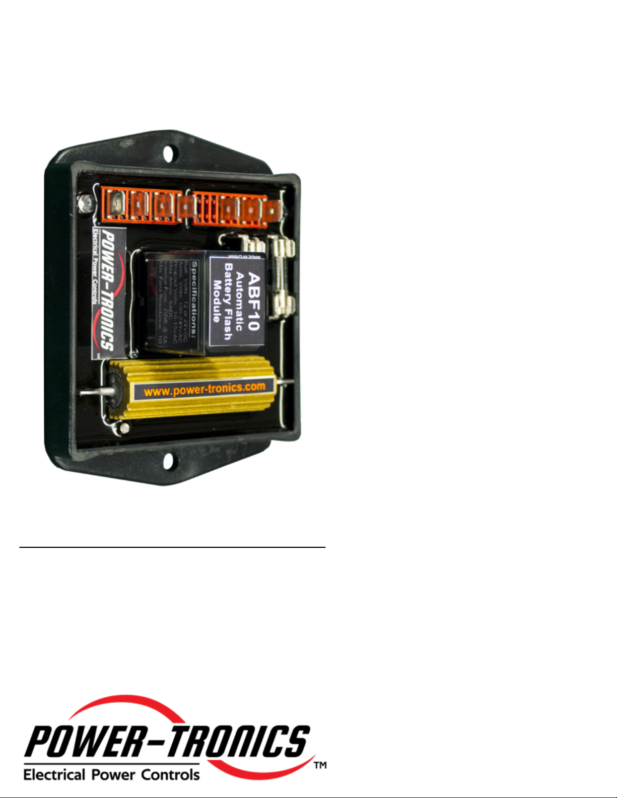
The Power-Tronics ABF10 Automatic
Battery Flash Module is a convenient and
compact optional automated flashing
module for all Power-Tronics voltage
regulating products and is compatible with
many other manufacturers’ voltage
regulators. The ABF10 offers an easy
method to add a fully automatic
aftermarket battery flash unit to any
generator.
The ABF10 is designed specifically for
automated battery flashing of a generator’s
control field. A reduced wire count and
generic installation make the ABF10
suitable for use on a wide range of
applications. Automating the battery field
flash improves reliability and greatly
improves safety for the operator.
Like the rest of our products, the ABF10
Automatic Battery Flash Module is
designed and manufactured with heavy
duty components to withstand the harshest
environmental conditions and provide
extreme reliability. Onboard fusing and an
encapsulated design mean the ABF10 will
stand up to extreme operating conditions.
Indicator lights help the operator know the
status of the flashing module and a voltage
operated design helps guarantee reliable
voltage buildup and a safe flashing
process.
Specifications
Sensing Voltage: 100-240vac
Frequency: 50-400Hz
Buildup Pullout Voltage: 10-15vac
Battery Voltage: 12-28VDC
Maximum Continuous Output: 5adc
Minimum Field Resistance: 1Ω
Battery Source: Customer-Supplied Battery
Fusing: Internal, GDB 5A @ 250V
Current Limiting Resistor: 20Ω @ 50W (Internal)
Physical Size: 4.1 x 3.1 x 1.675 in.
Weight: 7oz.
ABF10
Automatic Battery Flash Module

2
For Technical Support:
Visit our website at: www.power-tronics.com
Call Us at: (830) 895-4700
Table of Contents
Introduction and Functional Description:....................................................................3
Common 12-Lead Generator Wiring Diagrams:..........................................................4
Hookup Diagram:............................................................................................................5
Sequence of Operation:.................................................................................................6
Initial Setup and Commissioning:.................................................................................6
Application Troubleshooting:........................................................................................7
Bench Check Procedures:.............................................................................................8
Installation Warranty Form:...........................................................................................9
Product Warranty Certificate:......................................................................................10

3
For Technical Support:
Visit our website at: www.power-tronics.com
Call Us at: (830) 895-4700
Introduction and Functional Description
Caution: Read This Installation
Manual Carefully and Entirely!
Warning: Do not use digital equipment to read voltage, Hz, or amperage
during this installation. Use only Analog sensing equipment! Failure to do so
may result in damage to equipment or in personal injury!
ALWAYS perform all setup procedures off-line
ALWAYS wear eye protection
ALWAYS strip wire insulation properly or use insulated connectors
ALWAYS use analog metering equipment when setting up the regulating system
ALWAYS ensure the ABF10 is sheltered from weather and rain
NEVER hold the ABF10 in your hand when energized
NEVER install the ABF10 in a place it can get wet or is exposed to the elements
NEVER mount the ABF10 over a screw, bolt, rivet, welding seam, or other fastener
NEVER disconnect the wiring while the unit is in operation
NEVER insert a screwdriver or other object under the ABF10
NEVER install a switch in the DC portion of the module’s wiring
NEVER touch any exposed part of the ABF10 while in operation
NEVER USE A DIGITAL FREQUENCY METER (It can give a false reading!)
Functional Description
The ABF10 Automatic Battery Flash Module is a proven design based on industry-standard flashing
procedures and safety policies. The ABF10 provides a very compact automatic flashing or battery-
flashing source to any voltage regulation system quickly, easily, and safely.
When the generator is first energized, the voltage regulator typically begins its buildup mode where it
brings the generator up to a given point before it goes into its regulation mode. Sometimes, however, the
generator may have extremely low residual AC voltage or just have a hard time building up. In these
situations, the voltage regulator has a difficult time building up the voltage to a point it can regulate. The
solution in most situations like this is to flash the generator.
The ABF10 provides a fully automatic method to flash the generator during startup. Automatic flashing is
often used on generators with sliprings and brushes and for generators with very low residual AC voltage
(typically less than 3VAC) or in installations where a guaranteed buildup is required, such as hospitals,
nursing homes, or correctional facilities.
The ABF10 Automatic Battery Flash Module is based on time-proven flashing methods and features an
extremely robust and reliable design. Voltage sensing inputs are unfused to guarantee operation while
the battery input is fused to protect the flashing module and generator field in the case of a fault or
overload.
4
For Technical Support:
Visit our website at: www.power-tronics.com
Call Us at: (830) 895-4700
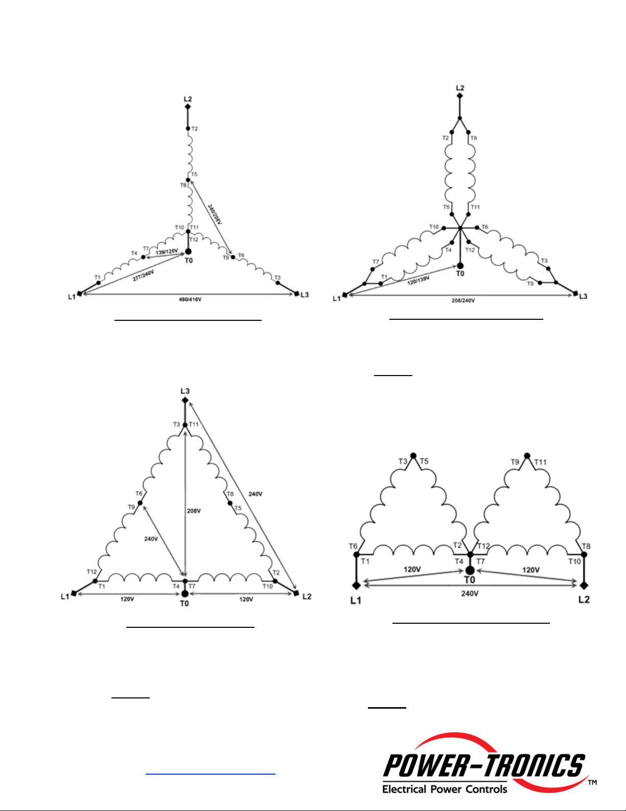
Common 12-Lead Generator Wiring Diagrams
Series Wye (416/480V 3ø)
Voltage L-L: 416/480V
Voltage L-N: 240/277V
Voltage CT – N: 120/139V
Parallel Wye (208/240V 3ø)
Voltage L-L: 208/240V
Voltage L-N: 120/139V
NOTE: 208V is Standard Voltage
Series Delta (240V 3ø)
Voltage L-L: 240V
Voltage L1/L2-N: 120V
Voltage L3 – N: 208V
NOTE: L3-N is a “High Leg”
208V instead of 120V!
Double-Delta (120/240V 1ø)
Voltage L-L: 240V
Voltage L-N: 120V
Preferred Single-Phase Connection.
Don’t Use Zig-Zag if Possible.
NOTE: Derate generator by 1/3 rated
capacity when using this connection!

5
For Technical Support:
Visit our website at: www.power-tronics.com
Call Us at: (830) 895-4700
Hookup Diagram
This configuration uses an external customer-supplied 12 or 24V battery to build the
terminal voltage to a point that the automatic voltage regulator can take over and
perform its function. The ABF10 will automatically disconnect itself when the sensed
voltage reaches approximately 10-15vac.
Take special care to follow the wiring directions precisely! DO NOT use a battery
voltage different from that marked on the ABF10 unit! Severe damage to the
ABF10 will result!
Note that the maximum input voltage to the ABF10 Automatic Battery Flash Unit
is 240VAC! DO NOT input 277VAC into the ABF10! Severe damage to the unit will
result! For use on 480V systems, either connect the unit to the winding center taps T7
and T8 or use a 480-240V step-down transformer.
Note 1: Customer-supplied battery and charging system. An isolated battery is strongly recommended!
Note 2: Flash-Enable switch. Should be open whenever the exciter is not operating. Rate at 28VDC, 10A or
greater. Switch may be a switched B+, oil-pressure switch, or pushbutton switch.
Note 3: If Using the ABF10 on a 480V or higher generator, connect terminals 1 and 2 to the center taps of the stator
leads T7 and T8, or use a step-down transformer as appropriate to supply 240vac to the ABF10.
DO NOT FUSE SENSING LEADS!!!
Note 4: Connect battery positive to “12” or 24” terminals for 12V or 24V battery applications
*Note 1*
*Note 2*
*Note 3*
*Note 4*
6
For Technical Support:
Visit our website at: www.power-tronics.com
Call Us at: (830) 895-4700
Sequence of Operation
1. Upon closure of the Flash-Enable switch, the ABF10 has a delay of approximately 1
second to allow the regulator to build voltage if able and to prevent accidental flashing of
the field once voltage has built to a suitable level.
2. After the delay has elapsed, the relay will close and apply battery voltage to the exciter
field. The green “Flash” light will illuminate during this time.
3. As the generator terminal voltage builds, the relay will drop out at approximately 10-
15VAC on the sensing leads. The green “Flash” light will go dark and the “Operating”
light will illuminate at this time. The voltage regulator should operate and raise terminal
voltage to the regulator’s setpoint
Initial Setup and Commissioning
1. Connect the ABF10 to the exciter field as shown in the instructions on Page 5, or to a
slave relay as shown on Page 6.
2. Verify wiring connections and start the generator.
3. Close the “Flash Enable” switch and observe that the terminal voltage rises. During the
flashing process, the red “Flash” indicator lamp will glow. When the ABF10 disengages,
the “Flash” lamp will stop glowing and the green “Operating” lamp will glow above 40vac.
4. After voltage has built up and the generator is operating, the “Flash Enable” switch may
be released or disconnected, or it may remain energized at the operator’s discretion.
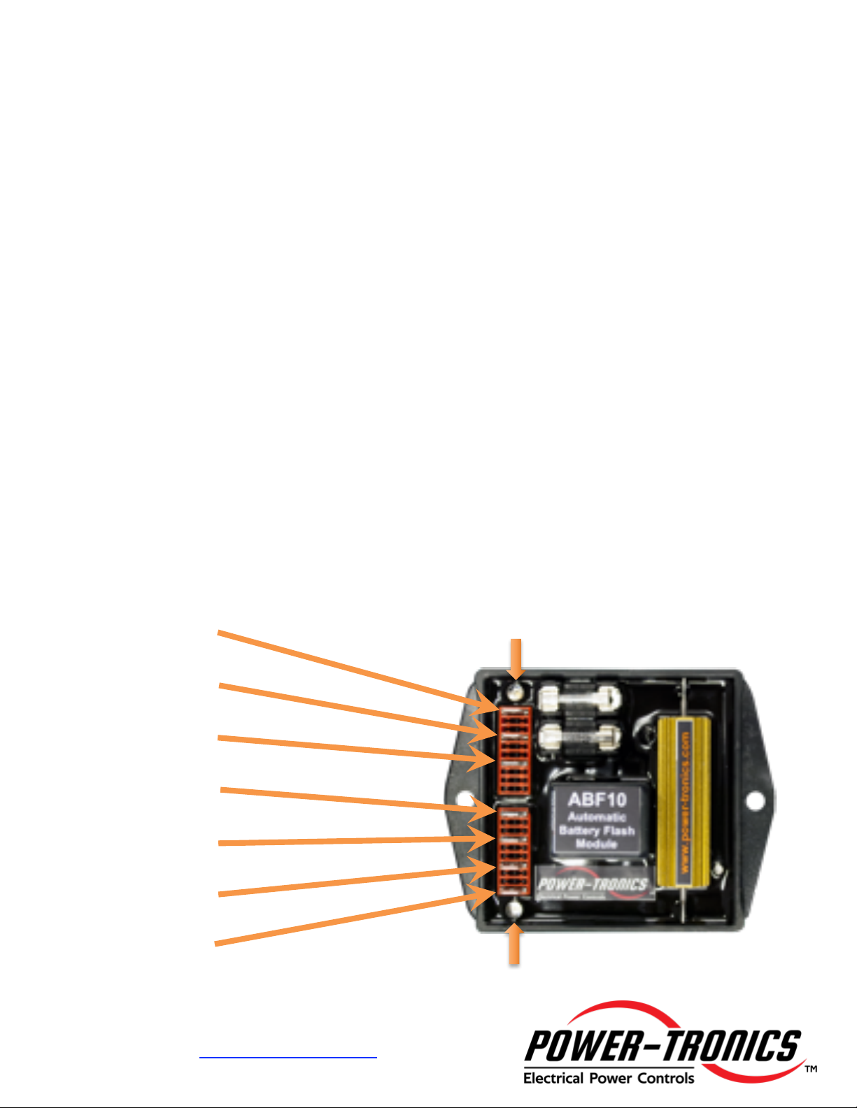
“Operating”
Indicator
Lamp
“Flashing”
Indicator
Lamp
12V B+
24V B+
B-
F-
F+
AC2
AC1

7
For Technical Support:
Visit our website at: www.power-tronics.com
Call Us at: (830) 895-4700
Application Troubleshooting
Problem: Possible Cause
No Voltage 1 2 3 4 7 15 18 21
Pulsating Voltage 1 3 5 6 7 10 13 14 20 21
Flickering Voltage 1 3 5 6 7 9 10 12 13 14 16 17 18 19 20 21
High Voltage 6 7 9 11 12 13 15 18 21 22 23
Low Voltage 1 2 3 4 6 7 10 11 12 13 14 15 20 21
Poor Voltage Regulation 1 5 6 7 8 9 10 12 13 14 16 17 18 19 20 21
No Voltage Control 1 3 5 6 7 8 9 10 11 12 13 14 15 16 17 18 20 21 22 23
Possible Causes:
1. Open or loose connection, poor brush and slip ring contact, fuses are open.
2. Dead battery.
3. Open exciter field or defective generator.
4. “Flash Enable” switch is open.
5. Open diode in exciter or shorted rotor in generator.
6. Loose component in voltage regulator.
7. Loose wiring connections.
8. Input voltage to regulator is too low.
9. Exciter field is grounded.
10. Non linear load or wrong selection for regulator hookup.
11. Exciter fields are reversed.
12. Wrong selection of regulator wiring configuration.
13. Defective voltage regulator.
14. SCR or Inverter drive effecting generator waveform.
15. Defective ABF10 Automatic Battery Flash Unit.
16. Isolation transformer is too small.
17. Isolation transformer is needed for AVR.
18. Exciter fields are not isolated from other circuits.
19. Input and field circuit are being fed by a common cable or conduit.
20. Incorrect hookup or wiring.
21. Exciter field is grounded.
22. Welded relay contacts.
23. Sensing leads disconnected, fused, or switched.
8
For Technical Support:
Visit our website at: www.power-tronics.com
Call Us at: (830) 895-4700
Bench Test Procedure
If you suspect a problem with your ABF10, it is possible to perform a bench test to verify
functionality of the unit and determine if a repair or service is necessary. To perform a
bench test on the ABF10, follow the directions below:
1. Connect a battery to terminals “12” or “24” and B- on the ABF10. Battery
voltage should match the voltage of the ABF10! You should hear a click
after approximately 1 second and the “Flashing” lamp should be
illuminated.
2. Connect a multimeter capable of reading DC voltage to F+ and F- on the ABF10.
3. You should read battery voltage at terminals F+ and F- on the ABF10 and
the “Flashing” lamp should be illuminated.
4. Apply 120VAC to terminals AC1 and AC2 on the ABF10. You should hear a
click and read 0VDC on F+ and F- on the ABF10. The “Operating” lamp
should be illuminated at this time and the “Flashing” lamp should be dark.
5. Remove the 120VAC from terminals AC1 and AC2 on the ABF10. After
approximately 1 second You should hear a click and read battery voltage on
F+ and F- on the ABF10. The “Operating” lamp should be dark and the
“Flashing” lamp should be illuminated.
6. Remove the battery voltage from B+ and B- on the ABF10. You should hear
the relay click and read 0VDC on F+ and F- on the ABF10.
If your ABF10 passed all of the operational tests above, the unit is good. If any one of
the tests failed or you are unsure of the result, please contact Power-Tronics for
assistance.
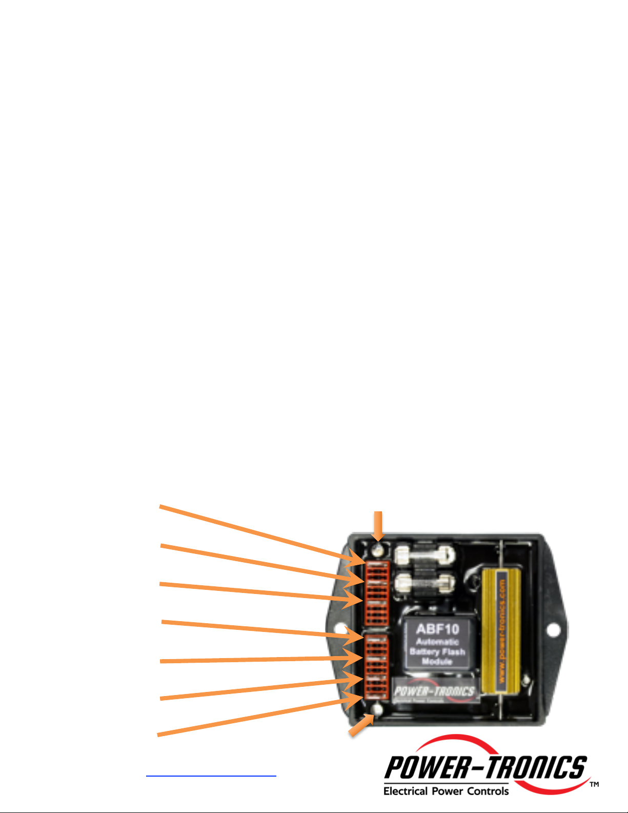
“Operating”
Indicator
Lamp
“Flashing”
Indicator
Lamp
12V B+
24V B+
B-
F-
F+
AC2
AC1

9
For Technical Support:
Visit our website at: www.power-tronics.com
Call Us at: (830) 895-4700
Installation Warranty Form
It is very important that you fill out this form completely when installing a voltage regulator. This form
serves as a history record on the application. This form also contains the information needed by
Power-Tronics, Inc., for repair and troubleshooting of any product you may be having problems with.
Failure to fill out this form during installation will result in a cancellation of your warranty
coverage! Filling out this form takes only minutes but will save hours or days later on if your
product should require service!
Problem Description/History (Please be detailed!!!):
Ship-To Address (City, State, Zip, Country):
Company Name:
Contact Person:
Telephone Number:
Email Address:
Primary Load (Please Explain):
Repair/Warranty Request Information
Generator Leads (Check One:) ☐12 ☐10 ☐6 ☐4 (3ø) ☐4 (1ø) ☐3
Generator Wiring Mode (Check One:) ☐High-Wye ☐Low-Wye ☐Series Delta
☐Zig-Zag ☐Double-Delta ☐Single-Phase ☐Other
Terminal Voltage:
Residual AC Voltage:
Rated KW:
Rated KVA:
Generator Wiring/Usage Information
This Section for Brushless Generators Only
Exciter Field Voltage:
Exciter Field Resistance:
This Section for Brush-Type Generators Only
Shunt-Field Voltage:
Shunt-Field Resistance:
Rotor Resistance @ Brush Leads:
Rotor Resistance on Slip-Rings:
Rotor Excitation Voltage:
Product Model:
Serial #:
Date of Installation:
Additional Module(s) or Options:
Submit Online at: www.power-tronics.com/warranty
Submit Online at: www.power-tronics.com/warranty

10
For Technical Support:
Visit our website at: www.power-tronics.com
Call Us at: (830) 895-4700
PRODUCT WARRANTY
Power-Tronics, Inc., assumes no liability for damages due to incorrect voltage or other voltage
related damages resulting from either output of the generator or input to the generator exciter
system. These problems should be protected with external devices provided by the customer
such as fuses, surge suppressors, over/under voltage and frequency controls.
Power-Tronics, Inc., warranties only parts and workmanship of this product for a period of 1
year from the original date of purchase from Power-Tronics, Inc. Under warranty, Power-
Tronics, Inc. will replace, exchange or repair the defective product without labor or parts cost
to the customer. Remaining warranty of the original product will be transferred to the replaced
or repaired product. To obtain warranty, a copy of the original Installation Warranty Form must
be sent in with the defective product, which clearly shows the purchase date and serial number
of the defective part. A repair request form must be sent in with the product before repairs will
begin. You can obtain this form by contacting Power-Tronics, Inc.
Send repairs to: Power-Tronics, Inc., 2802 Cobbler Ln., Kerrville Texas USA 78028.
Send in repairs only by UPS or FedEx. USPS will NOT deliver to our facility!
Any one of the following conditions will void the warranty:
v Overheating of the power supply resistor on the printed circuit card.
v Overheating of the blocking diode assembly.
v Physical damage to the printed circuit card, housing or components.
v Unauthorized repair or alteration of printed circuit card.
v Installation by anyone other than a qualified professional generator service technician.
v Conductive or corrosive contamination of the circuit card.
v Removal of our company identification from the product.
v Removal of any conformal coating of the printed circuit card or components.
v Bypassing or oversizing of the safety fuse.
v Inappropriate or infeasible application.
v Fused contacts or overheating of the relay.
v Failure to fill out the attached warranty card during installation
No other warranty is expressed or implied.
Table of contents
Popular Batteries Pack manuals by other brands


Nikon
Nikon SD-8a user manual

innonet
innonet P-LIGHT Magnum Installation and instructions for use

Yard force
Yard force VITA AL V40 Original instructions

Boyens Backservice
Boyens Backservice Jelly power pack instruction manual

BSLBATT
BSLBATT Powerline 5 installation manual

BYD
BYD HVL 12.0 quick start guide