Waterworld 48-6500 User manual

Version 1.2.2 - English 48-6500
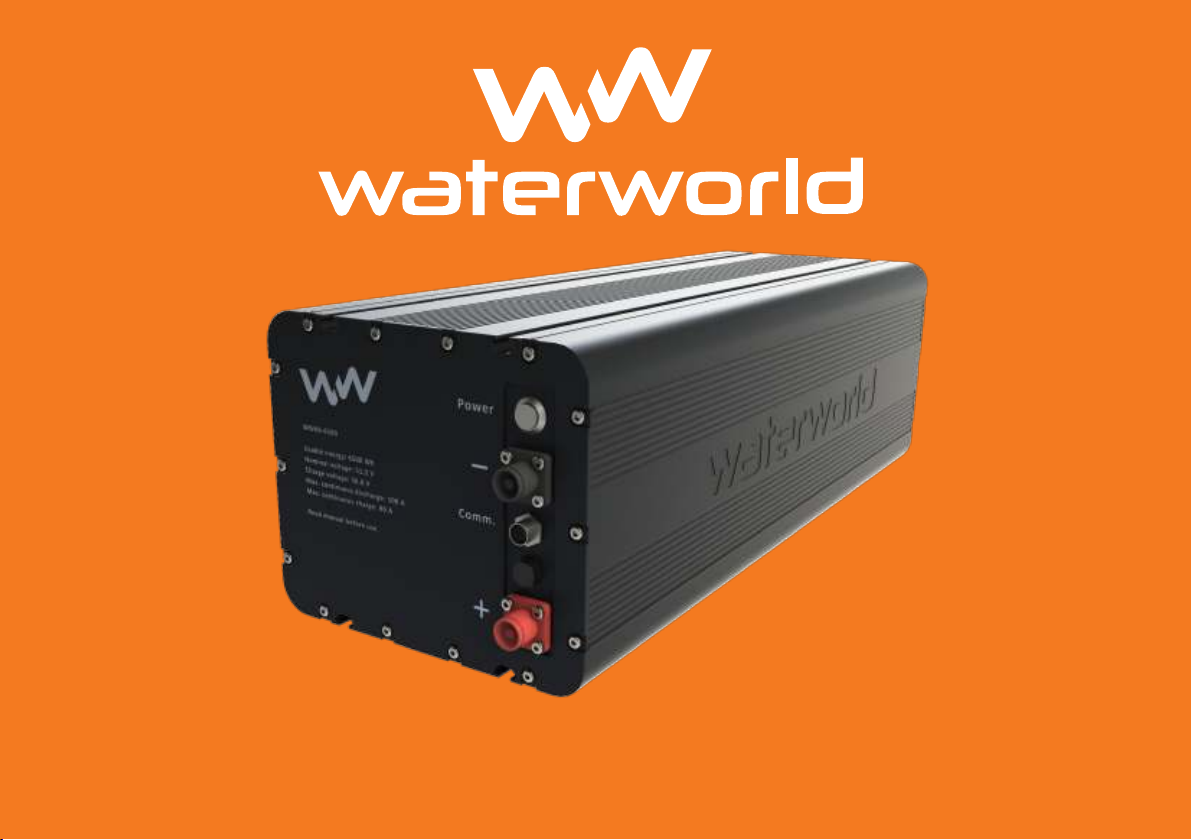
48-6500
Lithium Iron Phosphate battery

2
Water World Electronics
Weerdijk 14 – 8375 AX Oldemarkt
Telefoon: 0561 451 636
www.ww-el.com

3
Congratulations and thank you for purchasing the Waterworld 48-
6500 Lithium Iron Phosphate battery. At Waterworld it is our goal
to give our customers the best performing, most relieable and
safest battery system possible. To achieve this we need your help
during installation and operation. Please read these instructions
carefully to maintain our high standards during installation and
operation of the battery.
Also, reading the manual will teach you how you can get the
best out of your system and increase its longetivity!
If you have any questions or remarks regarding this manual or the
battery itself please feel free to contact us at:
We hope you enjoy your battery!
*Technical changes and errors in the manual are reserved. Always use the
latest version of the manual available at ww-el.com

Contents
1. Introduction 5
1.1 General information on the instructions 5
1.2 Safety information 5
2. Product delivery details 6
2.1 Overview of components 6
2.2 Overview and controls of WW 48-6500 6
3. Technical specications of 48-6500 8
4. Safety 10
4.1 General safety instructions 10
4.2 Safety introduction 10
4.3 Intended use 10
4.4 Unintended use 10
4.5 Before use 10
4.6 General safety information 11
5. Installation of the battery 13
5.1 Connecting multiple batteries in parallel 13
5.2 Installation 15
5.3 Wiring 15
5.4 Ventilation 16
5.5 Checking your system 16
5.6 Switching the battery on and off 16
5.7 Connecting the WaterWorld Battery Link 16
5.8 Functions of the WaterWorld Battery Link 17
6. Protection mode 18
7. Charging the battery 19
7.1 Overview of charging components 19
7.2 Connecting the charger to the battery 19
7.2 Charging the battery 21
7.5 LED status indicator 21
7.6 Error identication 21
4
8. Storage and maintenance 22
8.1 Storage 22
8.2 Maintenance 22
9. Error problem solving 22
10. Transportation guidlines 23
11. End of life and disposal 23
12. Tips to increase battery lifetime 23

5
1. Introduction
1.1 General information on the instructions
The instructions in this document describe all functions and pro-
vides safety information on the WW 48-6500 Lithium Iron Phos-
phate Battery.
It is our goal to make the use of our batteries as easy as possible
by providing all the information needed to understand, install
and operate the battery. This instruction manual ensures you are
able to operate the battery safely in compliance with its intended
use. If by any chance you feel information is not clear or are not
certain how to install or operate the battery, please contact our
customer service for your safety and the safety of the battery.
Always use the most recent version of these instructions which
can be downloaded on our website:
www.ww-el.com/downloads
By reading and following these instructions you will:
• Avoid dangers to yourself and your surroundings.
• Reduce outage times and repairs.
• Increase the lifetime of your battery and the reliability of your
system.
1.2 Safety information
In this instruction manual safety information will be presented us-
ing symbols and hazard classes. The hazard classes are subdivid-
ed in categories based on severity of the consequences and the
likelihood of occurrence. The hazard classes are depicted below:
Hazard classes
Danger!
Direct hazard with high risk.
Death or severe physical injuries may result if the risk is not
avoided.
Warning!
Potential danger
Severe physical injuries may result if theinstructions are not
followed properly.
Atttention!
Danger with low risk
Physical injuries may resultwhen the instructions are not followed
Advice
Mandatroy instructions
Use these instructions for safety and correct installation of your
battery.

6
2. Product delivery details
2.1 Overview of components
WW 48-6500 Lithium Iron Phosphate battery
The following components are included in the product package:
• 1x 48 Volt battery
• 1x User manual
• 1x Positive male cable plug*
• 1x Negative male cable plug*
• 4x M5 type 30 T-nut
Optional: Battery Link (needed in combination with a WaterWorld
drivetrain)
The following components are included in the product package:
• 1x Battery Link module
• 1x User manual
• 1x RJ45 waterproof data cable
2.2 Overview and controls of WW 48-6500
1. Power Button
2. Communication socket
3. Negative terminal
4. Expansion valve
5. Positive terminal
6. T-slots
7. Specications
Negative terminal connector
Positive terminal connector
1. Power on/off
2. Communication port
3. Positive terminal
4. Expansion valve
5. Negative terminal
6. T-Slot
7. Specifications
*available separate at your WaterWorld dealer

7
Power Button
Use the power button to remove voltage over the battery termi-
nals. When the switch is pressed in the battery is turned on and
it will have 51.2V (nominal) over its terminals. When the switch
is pressed again and the button is level with the enclosure the
battery is turned off and will not have voltage over the output
terminals
Communication socket
The communication socket is only used in combination with a
WaterWorld drivetrain. To enable the communiaction port a
WaterWorld communication gateway is needed. This is further
explained in chapter 5.5 of this user manual.
Negative terminal
The (female) black negative terminal (-) needs to be connect-
ed to the negative (-) terminal of your system. To do this use
the black (male) negative terminal connector provided to you
seperately. IMPORTANT! the female terminal is only waterproof
when covered by the plastic cover that comes with delivery or
when the male connector is plugged in. An open terminal is NOT
waterproof.
Expansion valve
The expansion valve regulates air pressure between the inside of
the battery and its outside environment. The valve is waterproof
as long as it is not damaged. Make sure that during installation
the expansion valve is safe from damage.
Positive terminal
The (female) red postitve terminal (+) needs to be connected
to the positive (+) terminal of your system. To do this use the red
(male) positive terminal connector provided to you seperately.
IMPORTANT! the female terminal is only waterproof when covered
by the plastic cover that comes with delivery or when the male
connector is plugged in. An open terminal is NOT waterproof.
T-Slots
The type 30 T-Slots in the alumuninium battery enclosure enable
attaching accesories to the enclosure. Four M5 nuts are provided
in the T-slot to attach the handles or rubber supports.
Specications
The most important specications to consider are engraved on
the enclosure. Make sure these are not damaged and can be
read by the user.
Serial number
The serial number can be found on the back of the battery. An
example of the serial number is: WWNL-22014865001

8
3. Technical specications of 48-6500
General Features
Capacity 6500 Wh
Nominal Voltage 51.2 V
Final discharging voltage 43.2 V
Maximum discharge rate 100 A
Maximum discharge rate at
nominal voltage
5120 W
Weight 60 kg
Dimensions (LxBxH) 650 mm x 255 mm x 215 mm
Volume 35.6 L
Battery Chemistry Lithium iron phosphate (LFP)
LiFePO4
Battery management and safety
On-off switch Yes
Cell balancing Yes
High current and short-circuit protection Yes
Deep discharge protection Yes, cut off at 41.6 V
individual cell string voltage monitoring Yes
Safety vent for each cell Yes
Cell temperature monitoring and pro-
tection
Yes
Temperature monitoring of battery
electronics
Yes
Low temperature shut off Yes
High temperature shut off Yes
Lifetime data
Cycle lifetime >4000 cycles with 80% dis-
charge depth at 25 °C to
capacity loss of 20% at 0.2 C

9
Battery composition
Capacity per cell 6 Ah
Nominal voltage per cell 3.2 V
Cell connection 16S22P
Information system
Interface CAN
Electronic battery identica-
tion
Yes
Error identication Yes
Use information
Ambient temperature, dis-
charging
-10°C up to +45°C
Ambient temperature,
charging
0°C up to +45°C
Ambient temperature, storage -25°C up to +60°C
Typical storage time at 50%
SOC
40 weeks without any load
(turned off)
Max connections Up to 1 Series 8 Parallel
Max quick charge 80 A
Protection class IP65

10
4. Safety
4.1 General safety instructions
Advice!
Read the instructions in this user manual carefully before oper-
ating the battery system. Always comply with safety warnings
stated in this user manual. Always stay alert while working with
and installing of the battery and other electric components
4.2 Safety introduction
The battery and its components are designed with safety and
user friendliness as a top priority and have been extensively test-
ed. However, dangerous situations may occur when the battery
is not handled properly or misused. This can result in physical harm
to persons or property. Always follow the guidelines stated in this
user manual as well as local safety and accident prevention
regulations.
4.3 Intended use
The WW 48-6500 battery can be used as a stand alone battery
or in combination with WaterWorld electric drive systems. Please
be aware the data cable is only compatible with WaterWorld
electric drive systems in combination with the WaterWorld com-
munication gateway. The maximum power output of the battery
is 5120 Watt. It is important to realise that when a bigger load is
connected the battery will shut off to avoid damage. The battery
must always operate in a system that respects its specications.
When a larger power is needed batteries can be installed in
parallel up to 8P.
4.4 Unintended use
The manufacturer accepts no liability when the battery is used
as anything that is not specically dened as its “intended use”
as dened in this user manual. All other use cases that are not
described in this manual are dened as “unintended use”. The
operator of the battery is solely responsible for any harm or dan-
ger arising from such unintended use.
Amongst others, the following are deemed unintended use:
• Permanent contact with water
• Use of third party battery chargers
• Use of cable sets that do not have a master switch or suf-
cient fuses
4.5 Before use
Before use check the condition and functioning of the battery.
The battery may only be handled and operated by adults.

11
Danger!
Fire Hazard! Danger to life
Always use appropriate conductive electric cable with the right
cross-section when connecting loads. If you are not sure what
cross section is needed please contact your dealer or another
professional or use IONBASE/WaterWorld branded cables.
Danger!
Fire Hazard! Danger to life
never use ammable gases, solvent or vapours on the system.
Danger!
Risk of death or severe physical injuries from electromagnetic
radiation
Persons with a cardiac pacemaker must maintain a 50 cm
distance from any IONBASE battery or charger.
4.6 General safety information
Please read the following carefully
Danger!
Risk of fatal electric shock!
Contact with uninsulated or damaged parts may lead to elec-
tric shock resulting in death or severe physical injuries.
• Never do any repair work to any part of the system your-
self. This leads to dangerous circumstances and voids the
warranty.
• Never touch any uninsulated or broken wiring or any other
damaged/defective parts.
• When you suspect a problem never touch any metal com-
ponents and switch off the main system switch and after
switch off the battery immediately.
• Prevent any electrical components from coming into con-
tact with water.
• Always have the battery switched off during installation or
during any form of handling the battery.
Danger!
Fire Hazard! Danger to life
Never charge the battery when it is damaged.

12
Caution!
Damage to the battery from heat
• Make sure the battery is never near external heat sources.
• Never store ammable objects near the battery.
• Store the battery in a well ventilated area.
• Never place the battery in direct sunlight. Especially during
summer or high ambient temperatures.
Advice!
Increase the lifetime of your battery by reducing its exposure to
extreme temperatures, moisture and direct sunlight.
Warning!
Danger injury by electric shock as result of short circuit
• Remove all metal jewelry before handling or installing the
battery or any other electrical equipment.
• Never leave tools in contact with the battery but store
them away at a safe distance.
• Always be aware of the polarity of the battery terminals.
Make sure you connect the battery at the correct polarity.
• Make sure the battery terminals are clean and free of
corrosion.
Caution!
Never open the battery
Opening the battery will void warranty and will lead to perma-
nent damage to the battery. Maintenance and repairs may
only be done by a certied professional.
Caution!
Fluids or gases leaking from a damaged battery can cause
injuries and other harm
• Avoid contact with any uids spilling from the battery.
• Avoid contact with skin and eyes.
• Never inhale gases from the battery.
• Contact your dealer or a professional in case of leakage
from the battery.

13
5. Installation of the battery
Important!Please charge your batteries before use.
Danger!
Danger to life from electric shock
• Avoid touching the battery terminals.
• Never undertake repair work on the battery yourself.
• Never touch any defective components
• Prevent any external forces from working on the battery
and the cables.
• If you detect any defect, shut down your system and the
battery immediately
Caution!
Damage to the battery and your system can result from incor-
rect installation. Please read the instructions carefully.
• Always make sure to turn the battery off during installation
using the main switch.
• Make sure to always rst connect the red positive cable to
the red positive terminal then connect the black negative
cable to the black negative terminal.
• When disconnecting the battery make sure to rst discon-
nect the black negative terminal before disconnecting the
red positive terminal.
• Never transpose the polarities!
5.1 Connecting multiple batteries in parallel
Danger!
Never connect the batteries in series! Fire and damage to the
battery and your system may result.
• Make sure to never connect multiple batteries in series.
• Never series connect the battery with any other third party
batteries.
Advice!
• Up to 8 batteries can be connected in parallel.
• For systems containing a WaterWorld drive train or con-
troller a gateway is required to be able to use the data
communication functions.
Important!it is very important the batteries are all at
the same voltage before connecting them in par-
allel. Please check the voltage difference between
the batteries is below 0.50 Volts. If not please charge
or discharge the batteries to equal voltage.
Important!Check your system for short circuit by
measuring the resistance of the system before
connecting your batteries. The resistance should be
>100 Ohm.

14
Connecting multiple batteries in parallel can be done in the
following ways of which method 2 is preferred:
Method 1: Note different cable thiknesses have to be used due to
the difference in current. IMPORTANT: for each battery the total
cable length of the negative side needs to be the same length as
the positive side.
Method 2: Using a positive and a negative busbar to connect the
batteries to makes it easier to handle the currents. IMPORTANT:
make sure each battery has equal cable lengths between the
busbar and hte battery for both the negative and the positive
sides.
-
100 A
200 A
100 A 100 A
300 A to Motor
+
100 A200 A 100 A
100 A
300 A to Motor
+
1
00
A
100 A100 A
300 A to Motor 300 A to Motor
-
Increment parallel connections -->
+ Busbar
- Busbar

15
5.2 Installation
Caution!
Damage to the battery and your system can result from incor-
rect installation. Please read the instructions carefully.
• Install the battery in a dry location that cannot be ooded.
• Do not install the battery near any heat emitting compo-
nents.
• Choose a well ventilated location for installation of the
battery.
• Make sure to always tightly fasten the battery to a base to
avoid any damage to the battery and its surroundings from
vibrations or shaking of the battery.
Installation using the T-slots of the battery enclosure
1. Place the battery in your chosen location and make sure the
location complies with the requirements mentioned above.
2. Use the T-slot to secure the battery to a solid base with bolts
of your choosing. It is also possible to strap the battery into
place using lashing straps.
3. Check if the battery is fastened securely.
Advice!
• Make sure the battery terminals and data port are easily
accessible and are not in contact or close near any other
objects that can damage the components.
• Make sure the equivalation valve on the battery is not
obstructed from functioning properly.
5.3 Wiring
Warning!
Danger injury by electric shock as result of short circuit
• Remove all metal jewelry before handling or installing the
battery or any other electrical equipment.
• Never leave tools in contact with the battery but store
them away at a safe distance.
• Always be aware of the polarity of the battery terminals.
Make sure you connect the battery at the correct polarity.
• Make sure the battery terminals are clean and free of
corrosion.
Always use cables with approriate thickness to handle the cur-
rents associated with your system. Table 5.3.1 provides guidelines
for choosing cable thicknesses at different electrical currents and
different cable lengths.
Important: add a 200 A fuse in line with each battery .
Table 5.3.1
Cable thickness guideline
length 1m length 3m length 10m length 15m
50 A 16 mm2 16 mm2 35 mm2 50 mm2
100 A 35 mm2 35 mm2 70 mm2 95 mm2
200 A 70 mm2 70 mm2 120 mm2
300 A 95 mm2 95 mm2
400 A 120 mm2 120 mm2
500 A 120 mm2

16
5.4 Ventilation
Caution!
Make sure the vent plug is free of obstacles and can operate
without obstruction
To prevent the battery from overheating please make sure the
battery is in a ventilated space. Positioning your battery in a well
ventilated and cool space will increase battery health and prod-
uct lifetime. The heat ns on the enclosure function as a heat sink.
Allowing airow over the enclosure will cool down the battery and
increase performance an product lifetime.
5.5 Checking your system
Before turning on your batteries please check your system for any
mistakes. Check your system for short circuit using your multimeter.
Make sure your system does not draw any small residual currents
<1A or <50W per battery. Loads under 50 Watt will not be detect-
ed by the BMS and can over longer periods of time affect the
SoC presentation. By charging the battery to 100% the SoC pre-
sentation is calibraterd. If there are any small loads in your system
make sure to charge your batteries to 100% more frequently.
5.6 Switching the battery on and off
To turn on the battery push the main switch(es) on the battery(s)
using the on/off switch on the front of the battery. The system
needs some time to start up. Note the battery is turned on when
the switch is clicked inwards. The battery is turned off when the
switch is level with the surface.
5.7 Connecting the WaterWorld Battery Link
When combining Waterworld 48-6500 batteries with a WaterWorld
electric drive a system can be created in which the battery and
motor communicate with each other. To enable this communica-
tion a communication gateway is added between the Water-
World system and the Waterworld battery. Figure 5.5.1 shows how
the system is connected. Always connect the rst battery in the
most left communication port 1. When adding batteries use the
rst port available to the right e.g. port 2, port 3, and port 4.
On the side of the Battery Link 2 CAN ports are located. Connect
the CAN communication cable to the gateway and to the other
side to any CAN port on the WaterWorld system.
The Battery Link feautures a LED light for every communication
port. This LED signals the status of the communication.
• Green: the battery has succesfully connected to the Water-
World system.
• Green blinking: the system is trying to connect. Please wait a
moment.
• Orange: The battery discharge is turned off. There is no volt-
age over the batteries terminals.
• Red: there is no connection detected between the battery
and the Battery Link. Please reset the system by turning of all
batteries and turning them back on after 30 seconds. If there
is still no connection please contact our customer support.
• LED off: there is no data cable connected. Please make sure
you properly connected the cable to the data socket on the
battery

17
5.8 Functions of the WaterWorld Battery Link
The BatteryLink integrates your batteries with the other compo-
nents of your WaterWorld drive. This results in an extremely reliable
system. In addition, the functions of the BatteryLink ensure that
your batteries are managed even better, so that they will last
longer. The functions of the BatteryLink are described below.
Accurate battery charge percentage
Due to the built-in smart shunt in the battery management system
in the battery, the current battery percentage of the battery is
always accurately communicated to the WaterWorld display.
The self-learning algorithm in the battery management system
corrects for degradation of your battery over time, so that the
battery percentage and sailing time remain accurate over the
entire life of your system.
High temperature power protection
When the battery gets too hot (60C+) it will switch off. To prevent
this, the BatteryLink will reduce the power of the motor before this
temperature is reached. When this happens you will receive a no-
tication in the WaterWorld display. Limiting the power gives the
battery(s) the opportunity to cool down and ensures a reliable
system that does not stop you unexpectedly.
Low temperature power protection
At low temperatures (below freezing) the BatteryLink protects the
battery. The power of the motor is reduced which gives the bat-
tery the chance to warm up before the maximum power can be
demanded. This will dramatically extend the battery lifetime.
Battery shut-off protection
In the case of a multi-battery system, it can happen unexpect-
edly that a battery fails due to low battery voltage, too high
temperature or some other problem. This can result in a chain
reaction where other batteries have to deliver too much power
beyond the limit as described in the specications. This results in
shutting down all battery(s) and thus shutting down the system.
To prevent this, in this event the BatteryLink will limit the power so
that the remaining battery(s) always continue to work within their
specications. This ensures that your system does not shut down
and you can continue sailing. You will receive a message in the
WaterWorld display with the error message.
Getting home safely
When the battery(s) are almost empty, it is important not to use
too much power from the engine as this can result in the batteries
failing. This is the case with all types of batteries. To minimize this
effect, with a low “state of charge” of the batteries, the maximum
power of the motor is reduced somewhat and you will receive
an error message. This ensures that you can always come home
safely and that you do not come to a standstill unexpectedly.
to

18
Error messages
When the BatteryLink limits the system, you will always be pro-
vided with a message in the display. This means you are always
aware of what is happening in the system.
6. Protection mode
The battery will go in protection mode when the battery is
operating outside its specication limits. There are two types of
protection. The rst protection switches off the battery, when the
conditions of the battery are back within its specication limits
the battery turns back on and is functioning again. The second
protection is irreversible and a dealer needs to be contacted for
service.

19
7. Charging the battery
Danger!
Fire hazard!
• Never charge a damaged battery.
• Do not use the charger near ammable or explosive mate-
rials and provide ventilation.
• The output voltage of the battery charger must be the
same as the specied charging voltage of the battery.
• Position the battery so that the fan can rotate properly and
blow air freely through the heat ns.
• Place the charger in a dry location where it will not be in
permanent contact with water.
• Do not open the charger to avoid electric shock
Always use a Waterworld certied charger to charge your battery.
Third party chargers are not supported and may damage your
battery.
When using a third-party battery charger, it should always be a
CC/CV lithium charger with the correct charging voltage.
Warning!
• Always use Waterworld approved LFP battery chargers.
• Make sure the charger is connected with the correct polar-
ity.
• Make sure the battery terminals are clean and free of
corrosion.
• The battery charger needs to be compatible with the bat-
tery and output 56.8 Volt.
7.1 Overview of charging components
The following components are included as standard:
• 1x 48 Volt 35 A Battery charger, EU plug - Anderson connec-
tor
• 1x Anderson connector connection set
7.2 Connecting the charger to the battery
Always be aware of the polarity of the battery. Make sure the
positive terminal of the battery is connected to the positive ter-
minal of the charger and the negative terminal of the battery is
connected to the negative terminal of the charger.
Never exceed the maximum charging current as stated in the
battery specications. Charge overcurrent will cause the battery
to go into protection mode and charging will stop. When multiple
batteries are connected in parallel the maxmimum charging
current is the sum of the individual max charging currents of the
batteries. In this case multiple chargers can be connected to the
batteries in parallel to achieve higher charge rates.
AC 220V

20
AC 220V
+
35A to battery(s)
-
Increment parallel connections -->
+ Busbar
- Busbar
A
C
220
V
35A to battery(s
)
Increment parallel chargers -->
Table of contents
Other Waterworld Batteries Pack manuals