manuals.online logo
Brands
  1. Home
  2. •
  3. Brands
  4. •
  5. Power
  6. •
  7. Garden House
  8. •
  9. Power 8ft User manual

Power 8ft User manual

Returns
If Power is not for you and you’d like to return your shed within 14 days of delivery, then we will collect the item
from you without charging a collection fee. No fuss, no fees!
All we ask is that you do not unpack the shed or take the shed off the pallet. You will be able to see the shed
panels on the pallet if you want to double check the quality of the shed panels.
You need to notify the company you ordered your garden building from to arrange a cancellation or return.
If you have unpacked the shed or taken the shed off the pallet, then you can still return the product to us
providing it is within 14 days of delivery, but you will have to cover the cost of returning the item. This will
either need to be arranging the delivery yourself (to our manufacturing unit in West Yorkshire) or repacking and
securing the goods back onto the pallet and we can arrange a pallet collection for you. The cost of this will depend
on your location and the item bought – please contact us if you would like us to advise the cost of this. In this case
we will not profit from any courier charges but simply pass on the cost we receive to you.
Any delivery surcharges you have paid (such as a quicker delivery, Saturday delivery, or a timed delivery) will not
be refunded.
Once your item has been returned it will be checked to ensure it is complete and in a re-sellable condition. If we
deem that the product is not in a re-sellable condition, we shall deduct a reasonable amount to cover any costs to
use or return them to you.
Where a refund is to be paid, we will usually refund any money received from you using the same method
originally used by you to pay for your purchase.
Contact Us
If you have any queries or issues with your shed then you can:
 Check out our FAQ page on www.PowerSheds.com
 Email us at hello@PowerSheds.com
Please provide photographs of any reported issues*
Any replacement parts can take 1-3 working days.
 Contact us via the telephone – 01274 036 577 (Mon-Fri 08:00 - 16:30)
 Write to us at:
Power Sheds Ltd
21 Commondale Way
Euroway Trading Estate
Bradford
BD4 6SF
 On the rare occasion that something is missing or damaged, please contact us to make us
aware so we can send out any replacements. Replacement parts will be dispatched within 1-3
working days.
 Please be aware we are unable to reimburse you if you purchase your own materials.
 We also cannot compensate for subsequential losses such as installation work.
Page 27
__________________________________________________
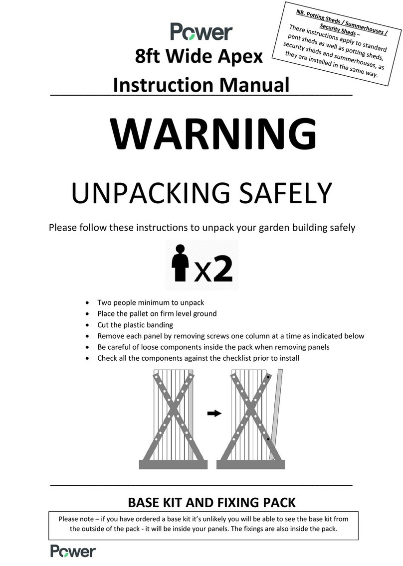
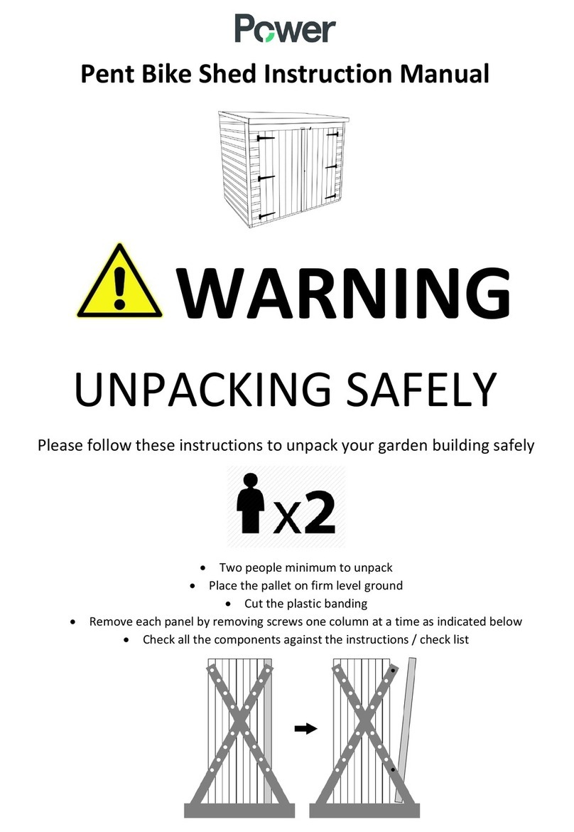
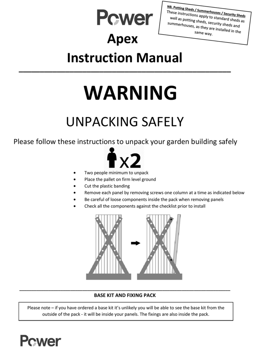
WARNING
UNPACKING SAFELY
Please follow these instructions to unpack your garden building safely
 Two people minimum to unpack
 Place the pallet on firm level ground
 Cut the plastic banding
 Remove each panel by removing screws one column at a time as indicated below
 Be careful of loose components inside the pack when removing panels
 Check all the components against the checklist prior to install
_______________________________________________________________________________________
BASE KIT AND FIXING PACK

8ft Deep Pent
Instruction Manual
Please note – if you have ordered a base kit it’s unlikely you will be able to see the base kit from the
outside of the pack - it will be inside your panels. The fixings are also inside the pack.
Power 8ft Deep Pent
Product Instructions
Watch the video!
We recommend watching our installation video before starting assembly of your Power shed.
This video can be applied to all pent sheds in our range
www.powersheds.com/fa
qs/how
-
do
-
you
-
assemble
-
a
-
power
-
shed/
Power Two-Tiered Staging Unit Installation Instructions
Power Shed Staging Units come at either 2ft or 4ft long.
You will receive the following components in each individual staging pack:
 (2x) Shelving Panels (either 2ft or 4ft)
 (2x) Legs (for the front of the panels only)
Please note:
 Depending on where you decide to install the staging units – you may need to cut the panels down. Before
attaching the panels to the framing ensure they are correctly sized.
 Use 70mm screws from the fixing pack to attach the shelving panels to the framing.
 When screwing the shelving into position, ensure they are fixed to the internal framing of the shed and not
the cladding
1. The staging units are designed to fit our Power Potting Shed window panels (however can be attached
to any shed in our range), by being fixed against the internal framing of the shed with the 70mm
screws.
2. Use a spirit level to ensure they are level. We would recommend to pre-drill the holes for the screws
to ensure the timber does not split.
3. Fix the legs to the shelves, once again using the 70mm screws.
After these are added continue adding each additional staging unit (if necessary) securing batons as
you go.
Returns
Page 26
Power Shed Shelving Instructions
Power Shed Shelving comes 4ft or 6ft long.
You will receive the following components in each shelving pack:
 (4x) board lengths (at either 4ft or 6ft, depending on what you ordered).
Please note: These are 70mm wide and are the same material as the bargeboards.
Be careful not to use these during assembly of your Power Shed – These boards are usually taped together.
 (3x) Brackets
 (2x) Batons
 (1x) Fixing pack - containing 70mm screws and 25mm screws.
Please note:
 When screwing the brackets into position, ensure they are fixed to the internal framing of the shed and not
the cladding.
 You may have to cut the board lengths down with a saw to fit, depending on the shed you have ordered.
1. Choose an appropriate location for your shelving and screw the brackets to the internal framing of the shed
using the 70mm screws.
2. Use a spirit level to ensure they are level.
Ensure the shelving bracket is the correct way up as per the following diagram:
Depending on your shed, there may not be an appropriate place to secure your brackets or there may be
framing in an unsuitable position (particularly if the shelf is going on a gable end). We have therefore sent
some additional batons to use if required.
3. After the brackets are attached to the framing of the side walls, you can fix the shelving board lengths into
the brackets with the 25mm screws. There should be two screws per board per bracket. There should be a
small gap between each board length
Page 25
Contents
Page 3 – Before You Start
Page 4 – Timber & Base Details
Page 5-6 – Components Checklist
Page 7 – Pre-Assembly
Page 8-13 – Floor
Page 14 – Door
Page 15 – 17 – Walls
Page 18 – Front Top & Gable
Page 19 – 21 – Roof
Page 22 – Felt
Page 23 – Finishing Touches
Page 24 – Aftercare & Maintenance
Page 25 – Shed Shelving Instructions
Page 26 – Two Tier Staging Instructions
Page 27 - Returns
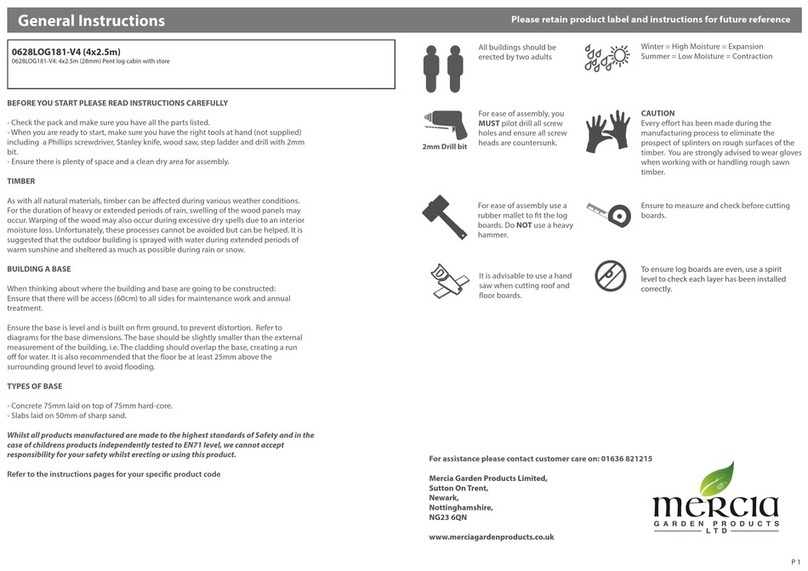
Before You Start
Most accidents are the result of negligence and carelessness, usually caused by the failure of the operator to
follow simple but necessary safety precautions.
Do not install the garden building before carefully reading this manual.
Visit www.Powersheds.com to check the base size for your shed and any other dimensions you may need.
Health & Safety
Every effort has been made during the manufacturing process to eliminate splinters on the timber.
You are strongly advised to wear gloves when working with or handling timber.
We also strongly advise you to wear safety glasses when installing the felt to protect your eyes.
2 persons recommended
Power Sheds Ltd cannot be held responsible for any damage or injury sustained due to incorrect unloading,
unpacking, or assembly of any of our products.
Tools Required
(not supplied)
Drill Spirit level Hammer Stanley knife Stepladder Saw Silicone
Our Treatment
Wear gloves when handling freshly treated wood.
Avoid breathing dust when cutting treated or untreated wood. Dispose of off-cuts responsibly – do not burn.
Contains: IPBC (3-iodo-2-propynyl-N-butyl carbamate) and propiconazole.
May produce an allergic reaction (EUH208). Causes serious eye irritation (H319) Wash skin thoroughly after
handling (P264) Wear protective gloves/protective clothing/eye protection/face protection (P280)
IF IN EYES: Rinse continuously with water for several minutes.
Remove contact lenses, if present and easy to do and continue rinsing. (P305 + P351 + P338)
If eye irritation persists: Seek medical advice/attention (P337+P313)
Page 3
Aftercare & Maintenance
Seal Your Windows
We recommend windows are sealed externally with the application of silicone, putty, or any other ‘watertight’
solution of your own preference.
Important!
Please ensure you thoroughly seal the exterior bottom corners of the windows at the edge of the sill. If you
have a Summerhouse, remember to seal around the door glass as well!
Shed Preserver
All our sheds come with our Power preservative.
It is important that you re-treat your Power shed annually with a high-quality wood preserver.
Feel free to change the colour of the building giving you the ‘power’ to style it your own way.
Take extra care to brush treatment into all wooden components inside and outside.
Please ensure there are no overhanging branches or debris on the shed as this can lead to water ingress.
USEFUL TIP – Looking for some inspiration?
Our Instagram has images of hundreds of Power Sheds which have all been sent to us by customers and is a great
way to look at the different ways you can build and paint your shed!
Check Your Base
Your base should be level at the time of assembly, but please note that some bases can move over time and if this
occurs, then the building can twist, or door may not close properly.
If this happens, you may need to pack up the base to keep the building level.
Share Your Shed
Here at Power, we love to see your sheds!
Send us photos of your finished sheds to our social media channels using the following handles –
@PowerSheds #PowerSheds
Instagram Twitter Facebook
Page 24
Finishing Touches
1. Using the 40mm galvanised nails, fit the bargeboards to the front and sides of the roof.
These may need cutting down with a saw depending on what size building you have.
2. Secure corner strips at each corner of your Power shed with 40mm nails (at least four per strip).
Extra strips are provided to cover any joins between side wall panels.
3. Secure the door pull to the door with 25mm screws.
4. Ensure there are no overhanging branches or debris on the shed as this can lead to water ingress.
Please be aware, this will need to be checked regularly as part of the maintenance of the shed.
Page 23
Watch the build a base video:
www.powersheds.com/faqs/how-do-you-assemble-the-power-sheds-base-kit/
Timber
As timber is a natural product, it is prone to changes in appearance, including but not limited to movement, warping
and splitting, particularly in extreme weather conditions. There may be the occasional split, knot or similar visual
imperfections in the timber.
Whilst every effort is made to hand pick timber without visible knotholes or splits there may be occasions where
timber is selected in good faith that contains what appears to be a solid knot. Over the course of time/during
movement of the product, it may be that these small knot holes are then dislodged from the timber leaving a small
knot or crack.
Unfortunately, we cannot be held responsible for this maturing of the product and can only offer our best advice as
to how to deal with this situation in the unlikely event that it should occur. Our advice would be to apply some wood
filler to the area affected or in extreme circumstances to change the board over.
None of this should affect the structural integrity of the product.
Firm & Level Base
All our garden sheds require a firm and level base.
When thinking about where the garden building and base is going to be constructed:
 Ensure that there will be access to all sides for maintenance work and annual treatment.
 Remember not to place the base too close to any walls or fences, as there may be a slight
overhang on the roof which may come into contact with the wall or fence.
 Ensure the base is level and is built on firm ground, to prevent distortion.
 Refer to PowerSheds.com for base dimensions.
 Consider when placing the base next to trees or large bushes as this could cause problems
from overhanging branches. If these are likely to grow and come into contact with the
building in the future this could cause the felt to rip.
The base is slightly smaller than the external measurement of the building, i.e. The cladding should overhang the
base, creating a run for water.
It is recommended that the floor is at least 25mm above the surrounding ground level to avoid flooding.
If you have not chosen to purchase our Power Base, then other suitable bases would include a concrete base
(75mm of concrete on top of 75mm of hardcore) or a paving slab base (slabs laid on top of 50mm of sharp sand).
Power Base Kit
If you have ordered a Power Base Kit the instructions can be found in the small base kit fixing pack.
Please scan the QR code to watch our base kit installation video -
Page 4
Component Checklist
Page 5
Felt
Health and Safety – Use safety goggles when installing the roofing felt.
1. Before laying the felt, you will need to attach the vertcal low side bargeboards. There are 70mm
wide boards to go on the edge of the roof on the LOW SIDE ONLY. Use the 40mm galvanised
nails to secure. (Note – no bargeboards goes on the front yet – wait until the felt is on)
These bargeboards may come in more than one section and may need cutting down to size with
a saw, depending on which size shed you have chosen.
Be sure not to mix these up with the cover lats (58mm) which are to go around the shed in
corners and covering joins (explained later).
2. Then, the underside soffit, which is 90mm deep, goes on both the front and the back, under the
roof overhang. These may also need cutting down to size and secured with 40mm galvanised
nails.
3. Roll out the mineral roofing felt along the length of the lower section of the roof. Allow for
sufficient overhang to fold down onto (but not under!) the roof bargeboard.
Health and Safety – Use Step Ladders to put on the roof felt but do not climb on top of the roof.
Ensure there is a second person to support you when using a ladder.
Note – If you are unsure on how to felt the roof, please contact us directly for more
information.
Please be aware, we cannot reimburse you if you choose to purchase additional materials
or incorrectly cut down provided materials.
4. Use clout nails to tack along the top edge of the felt and into the roof board and the bottom edge of the
felt into the back bargeboard.
5. Repeat this process along the higher part of the roof.
6. Fold down the overhanging felt on the gable ends and tack this into place.
Front and side bargeboards will cover any untidy edges.
Important!
Take care not to tack into the tongue and groove join
between each board as this can cause leaks.
Tip!
The underside soffit can be left off to allow for
additional ventilation in your shed.
Page 22
3. Make sure the framing on the roof is in line with the framing on the gable top so that the overhang on
the front and back is correct.
If the framing does not align the base may be very slightly out and the two opposite corners of the
floor may need lifting. More details on bases can be found on www.powersheds.com/how-to-build-a-
shed-base/
4. Use 50mm screws to join the roof panels to each other, to the framing, and to the gables. Ensure you
are screwing through the framing from the inside of the building. You may need to pre-assemble the
roof panels in sections before fitting them in position.
5. Screw the roof panels to the side wall panels with 50mm screws (ensuring you screw up through the
framing from the inside of the building into the framing on the roof panels).
Note – The roof panels are not handed, it does not matter which way round they go.
Page 21
Please note you will also be provided with 1x 300mm batten per floor panel, along with your oth
er components. These are to be used when assembling the floor.
Page 6
The Fixing Pack
Your fixing pack will include:
 25mm screws
 35mm screws
 50mm screws
 70mm screws
 Clout nails (for the felt)
 Door handle
 Turn buttons
If you have ordered a Power Base, you will also receive 80mm and 100mm screws.
On the rare occasion that not enough screws are provided please contact us to make us aware so we can send
more out to yourself. Please be aware we are unable to reimburse if you purchase your own.
Pre-Assembly
1. Safely unpack your components and check that you have all the parts required.
Please use the table in the two previous pages to view which components are required for the size you have
ordered.
2. Carefully remove the pallet and any untreated packing timber.
See the aftercare section on ways to recycle these items or alternatively you can discard them.
3. Remove any transport blocks from the bottom of the blank and window panels. These are there to offer
further protection to the bottom board of the panel.
USEFUL TIP!
Re-treat the underside of the floor before assembly for additional protection and maximum longevity.
Drilling
In the instructions we will talk about screwing panels together.
We recommend that this is done with a drill as will minimise the chance that the timber will split.
We suggest that you pre-drill the timber with a 3mm drill bit before inserting the screws.
Page 7
As you can see, the smaller panels are in alternating positions.
Then consider the additional 1890mm framing pieces used to strengthen the roof joins, as pictured
below.
Page 20
Roof
1. Depending on the building size you have ordered, your roof panels will be in sections. Please consult
the components check list regarding roof panels.
The framing on the roof panels will run front to back, from the high side to the low side – and you will
need to join the roof panels to bring them to full size.
i.e. there will be a 6ft roof panel and a 2ft roof panel to create an 8ft panel.
2. You will need to place the roof panels in position so that the framing on the roof panel runs parallel
with the gables i.e. from the front high side to the back low side.
These panels will need joining together so that they are 8ft long. To ensure the maximum strength
when joining the panels, we have supplied additional framing pieces to be used as additional support.
This is demonstrated in the 2nd image on page 20. We also highly recommend alternating the roof
joins as you work across to ensure the roof does not sag over time.
For example, if we look at a 16x8 roof, we would have (4x) 4x6 Pent Roof panels and (4x) 4x2 Pent
Roof panels. Please see the images on page 20 and use these as a layout guide, allowing for the
variation in quantity depending on the size of shed purchased.
2x6 Pent
Roof
2x2 Pent
Roof Panel
4x6 Pent
Roof
4x2 Pent
Roof Panel
1890mm
Framing
1302 x
90mm Lats
4x8 1 1 2 2
6x8 1 1 1 1 4 4
8x8 2 2 6 4
10x8 1 1 2 2 8 6
12x8 3 3 10 6
14x8 1 1 3 3 12 8
16x8 4 4 14 8
18x8 1 1 4 4 16 10
20x8 5 5 18 10
Page 19
Floor
1. Your shed floor will come in a number of 4ft x 4ft panels and for some sizes 4ft x 2ft panels. Please use
your component list to identify your panels.
These need to be laid out on to your firm and level base into the desired position of your shed.
2. Be sure to consider any overhangs on the shed when deciding the correct position as per the
instructions regarding bases in the ‘Before You Start’ section.
The layout of the floor is as follows:
Page 8
Page 9
Front Top & Gables
1. Add the pent front top to the side you want to be the ‘high side’ and screw through the framing, into
the panels below with 50mm screws.
Note - Please ensure that the 4ft pent top is on top of the 4ft panel and any 2ft pent tops are placed
up on the 2ft panels as this will ensure that the cover lats align.
2. Line up the gable tops with the panels at the gable ends (the ends where you attached the ‘heavy-duty
bearers’) and secure them to the wall panels with 50mm screws from the inside, screwing upwards
through the framing.
Note – The gable tops will come in two halves!
Page 18
7. Position another wall panel and secure using the 50mm screws provided.
Use three screws per join.
8. Continue this process until all remaining wall panels are in position.
9. When you have secured all the wall panels (door panel, 2ft and 4ft blank panels, window panels) you
then need to secure these to the floor using 70mm screws provided. Screw into the floor from inside,
with 2x screws for every wall panel, ensuring the screws are driven through the framing at the bottom
of the side/gable walls, through the floorboards and into the floor joists.
USEFUL TIPS!
You can work out the position of the floor joists from the location of the nails in the floor.
It may need screwing at an angle to ensure the screws go into the floor joists as bracing or upright pieces
of framing could be in the way
If you are securing these panels against a wall (which gives you little access to nail the cover strips on,
explained later) you can pre-assemble a side and move the whole side into position (with the cover lats
already nailed on)
Page 17
And so on, up to the 20x8 which will be:
Page 10
As you can see, the floor panels with the full board will be central (so join with the groove of one panel meeting
the groove of the joining panel), and the cut board will be to the edge of the building –
3. You now need to join the floor panels together.
To do this you will be provided with a number of joining batons to aid you.
Important!
Although the outer bearers will line up, the central bearers may not.
This is completely normal and nothing to be concerned about.
4. For each row of floor panels, turn them upside down and join using joining blocks as below. Use two
50mm screws per joining block to create 8ft floor panel sections:
Page 11
5. Continue by positioning one of the 4ft or 2ft panels at a right angle to the 4ft wall panel you have
already installed to create the first corner.
6. Secure these panels together from the inside using the 50mm screws provided, using three screws per
join.
Important!
When securing these panels together, ensure they line up at the top (so the building is square) and that
only the ends of the cladding are shown, which will later be covered with corner strips.
This is only in the corner when the side meets the gable.
8ft Gable End Side
Page 16
Walls
1. Please ensure you have removed the transport blocks as per the pre-assembly section.
2. Your garden building will come with a number of wall sections. The quantity of these will depend on
the type and size you have ordered. Please see the components table to confirm which panels you
should have for your building.
3. Lay out the wall panels in the configuration you want for your garden building.
The blank panels, door panel and window panels can go in any position.
We give you the ‘power’ to choose how you want your shed!
4. Start with the first 4ft panel that will be part of your gable end – position this on top of one of the
heavy-duty bearers which you attached in the ‘Floor’ section. Ensure the side of the panel is flush with
the side of the floor.
Page 15
5. Leaving the floor panels upside down, you can join the sections of floor panels together using 6 x
50mm screws per join, as below:
6. At this stage we would advise turning these floor panels back the right way round.
If you continue to add and join more floor panels while the panels are upside down, you will find it
very difficult to turn them back over once finished.
You can then repeat the process with the next set of floor panels until the whole floor is back the right
way around.
7. You now need to join the larger sections of two or four floor panels together so that the whole floor is
joined.
For the larger sizes, where you couldn’t join the whole floor together upside down, you will need to
join the sections together whilst it is the correct way up. To do this, simply screw the floor joists
together at the side of the floor, at an angle, connecting the two floor joists together. Do this with
70mm screws and be sure to pre-drill the timber to avoid splitting.
Page 12
8. Once all the floor panels are the correct way up and screwed together, you then need to screw the
four ‘heavy duty bearers’ which are two pieces of framing joined together, to each gable end (the end
where the triangular ‘gable tops’ will go later’).
There will be (4x) 4ft bearers – two for each 8ft end.
Important!
Whichever size shed you have; the bearers must go on the 8ft gable ends.
E.g. if you have a 4x8, still put the bearers on the 8ft sides (even though the bearers come in 4ft
lengths).
E.g. If you have an 8x8 shed, ensure you’re fitting the HD bearers to the gable ends, where the
triangular gable pieces will later be positioned.
Page 13
Door
1. Your building will either come with a single door or a double door depending on what you selected when
ordering. Double doors are already hung on the door panel. However, for a single door you will need to
hang the door. The key is screwed to the back of the door on the underside of the framing.
For a single door you can choose which way round to hang it – left hand or right hand.
Note – If you choose a left-hand hinged door then the lock must be unscrewed and positioned the
correct way round as it will be upside down
2. For a single door, lay the door panel on the floor and line up the door up with the framing so that it is
square. The door should be positioned centrally, with an even gap on both sides.
Make sure the lock is on the inside of the shed when the door is closed. Secure the hinges in place
using the 25mm screws provided.
3. Choose two places on the door to secure your two turn buttons – one towards the top, one towards the
bottom. For double doors a turn button will already be secured. Be careful not to screw this too tightly
or it will not turn.
(Example image - The style of door may vary depending on the building you have ordered)
Important!
Make sure the door is unlocked before the next stage or once you have assembled the side walls you will
not be able to get in your shed.
Page 14

Other manuals for 8ft

1

Other Power Garden House manuals

Power Pent User manual

Power

Power Pent User manual

Power Apex Instruction sheet

Power

Power Apex Instruction sheet

Power Apex Instruction sheet

Power

Power Apex Instruction sheet

Power Pent User manual

Power

Power Pent User manual

Power Apex User manual

Power

Power Apex User manual

Popular Garden House manuals by other brands

ABSCO SHEDS 30152GK manual

ABSCO SHEDS

ABSCO SHEDS 30152GK manual

Outdoor Life Products BZ2828 manual

Outdoor Life Products

Outdoor Life Products BZ2828 manual

Palmako Trinity installation manual

Palmako

Palmako Trinity installation manual

FIberWood FW-E2854GW-001 installation instructions

FIberWood

FIberWood FW-E2854GW-001 installation instructions

Palmako Aubagne 5 Assembly, installation and maintenance manual

Palmako

Palmako Aubagne 5 Assembly, installation and maintenance manual

Shire Rose Arbour Assembly

Shire

Shire Rose Arbour Assembly

Reynolds Building Systems Pinewood 1420 Assembly Book

Reynolds Building Systems

Reynolds Building Systems Pinewood 1420 Assembly Book

Lemeks Palmako PM70-5242-1 Assembly, installation and maintenance manual

Lemeks

Lemeks Palmako PM70-5242-1 Assembly, installation and maintenance manual

Palmako Nordic + LA90-2926 installation manual

Palmako

Palmako Nordic + LA90-2926 installation manual

Best Barns Belmont II Assembly Book

Best Barns

Best Barns Belmont II Assembly Book

Lemeks Palmako PA28-2929-1 Assembly, installation and maintenance manual

Lemeks

Lemeks Palmako PA28-2929-1 Assembly, installation and maintenance manual

Palmako FRZB44-6041 installation manual

Palmako

Palmako FRZB44-6041 installation manual

total sheds Pent Summer Shed 14x7ft Assembly manual

total sheds

total sheds Pent Summer Shed 14x7ft Assembly manual

Yardistry YM12842 Installation and operating instructions

Yardistry

Yardistry YM12842 Installation and operating instructions

Wolff Finnhaus ELEGANTO 2724 Technical Data/Assembly Instructions

Wolff Finnhaus

Wolff Finnhaus ELEGANTO 2724 Technical Data/Assembly Instructions

Palmako PA34-3434-6 installation manual

Palmako

Palmako PA34-3434-6 installation manual

Reynolds Building Systems Best Barns Deluxe Woodville Assembly Book

Reynolds Building Systems

Reynolds Building Systems Best Barns Deluxe Woodville Assembly Book

Mercia Garden Products 03TGCOR0909DDFW-V1 manual

Mercia Garden Products

Mercia Garden Products 03TGCOR0909DDFW-V1 manual

manuals.online logo
manuals.online logoBrands
  • About & Mission
  • Contact us
  • Privacy Policy
  • Terms and Conditions

Copyright 2025 Manuals.Online. All Rights Reserved.