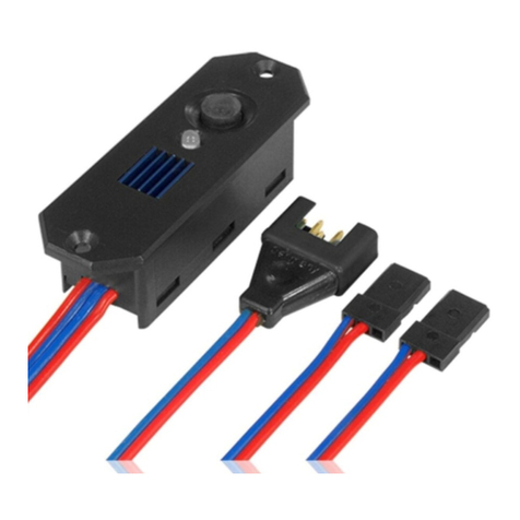
PowerBox Systems PowerBox 40/24 Champion User manual

Operating Instructions
Brief description of the PowerBox 40/24 Champion
Petty patent No.: 203 13 420.6

This power supply system, based on the PowerBox Competition, offers a range of
new, valuable and practical features in addition to those of its predecessor, which
will be of great advantage to many model applications.
Naturally the unit features double voltage stabilisation of the battery voltage for
servos and receiver at 5.9 Volts, as featured by the PowerBox Competition. The
two electronic switches can be operated by the SensorSwitch. The voltage
monitor system makes use of two LED chains and external LEDs, together with a
low voltage memory which monitors each battery. Viewed overall, this represents
the most reliable and sophisticated method of voltage monitoring available in any
power supply system.
The PowerBox Champion also features a facility for individual servo adjustment
on 3 channels and 12 servos (Servo Match Control). An Adjustor Board can be
connected and disconnected from the unit at any time using the captive cable
(approx. 1 metre long), and the board is used to adjust and program the indi vidual
channels and servos. One Adjustor Board can be used for any number of Power-
Box Champions, and this provides a useful cost saving when you purchase addi-
tional units.
The system provides 7 channels which are accessed remotely from the receiver. All
channels are equipped with the latest short-circuit protected signal amplifiers
(advanced push-pull), and a separate signal is fed to each of the 24 servo sockets.
The signal amplifiers are voltage-independent; we also stabilise the servo signal.
Before you use the PowerBox Champion in your model it is necessary to carry out
an initialisation process in order to obtain optimum results in terms of servo oper-
ating characteristics. This process is necessary because every radio control system
manufacturer uses a slightly different neutral pulse width and end-points, and toler-
ances in the stick units may also arise. The advantage of the initialisation process is
that the PowerBox Champion can be used with all radio control systems, as it is
capable of compensating for any inaccuracy or wear in the potentiometers of the
stick units.

POWER BOX 40/24
- 2 -
The first time you use the backer you must start by initialising the unit.
•Connect both receiving system batteries to the backer with correct polarity.
•Connect all the servos to the PowerBox Champion in the appropriate se-
quence.
•Switch on the transmitter and receiving system.
•Connect the Adjustor Board to the PowerBox Champion.
•Make sure you understand how the controls of the Adjustor Board are used.
The upper rotary knob is the channel select switch.
The lower rotary knob is the servo select switch.
Servo travels are adjusted using the two press-buttons + and -.
The red LEDs indicate that you have not yet stored the last process.
The yellow LEDs indicate that you have adjusted the servo centre setting.
Now to initia lise the Pow erBox Champion:
1. Move the channel select switch to “A”.
2. Move the se rvo select switch to “re se t”.
Start with the channel of your transmitter which is used to control socket bank “A”
on the backer, and check that the trim is at centre!
3. Leave this stick at “ne utra l” and press the + button. The first red LED will glow,
together with the yellow LED associated with this channel.
4. Move the stick to the right-hand end-point and press the + button.
5. Move the stick to the left-hand end-point and press the + button. The provi-
sional result: the yellow LED goes out.
6. Move the servo select switch to the “sa ve ” position, and press the + button.
The red LED goes out. This completes the initialisation of channel “A”.
This channel of the backer is now set up correctly to match the values of your radio
control system.
Repeat the whole process with the channels for socket banks “B” and “C”.

POWER BOX 40/24
- 3 -
1. - Set the channel select switch to “B”.
2. - Set the servo select switch to “reset”.
3. - Stick neutral, trim central, press + button, yellow and red light up.
4. - Stick right, press + button.
5. - Stick left, press + button.
6. - Set servo select switch to “save”, press + button, job done.
Both LEDs (red and yellow) should now go out, confirming that the initialisation
process of this backer channel is also concluded.
Repeat the procedure with socket bank “C” and the associated transmitter
stick.
If you make a mistake, set the servo select switch to “reset” and press the + and -
buttons simultaneously. This resets the values for the channel concerned, and
you can re-start the set-up procedure for that channel.
Now you want to adjust the servos of one channel:
Select the appropriate socket bank on the Adjustor Board (A, B, C).
Select the servo to be adjusted using the servo select switch. The servo socket at
the outer edge of the PowerBox Champion is Servo “1”; the innermost servo of
the bank of four sockets is Servo “4”.
You can now adjust the centre, right and left servo end-points for that servo. To ad-
just the end-points you must hold the corresponding transmitter stick in the appro-
priate position.
You can now set the servo travels precisely using the + and - buttons. Note that it is
also possible to set non-symmetrical values. For coarse adjustments you can
hold the button pressed in, and the servo will move continuously in the desired di-
rection. For fine adjustments press the button briefly.
To reverse the servo move the transmitter stick to one end-point, then hold one but-
ton pressed in until the servo runs to the opposite end-point. This may take up to
30 seconds. This means that you can watch what is happening; after all, you don’t
have to reverse servos every day. Move the stick to the opposite end-point, then
hold the other button pressed in and allow the servo to run to the other
endpoint.

POWER BOX 40/24
- 4 -
It is possible to set any (!) servo travel that you wish, but please take care! In prin-
ciple you can set up any servo to move through an angular travel of 180°. How-
ever: not every servo is mechanically capable of such travels (gearbox end-stops).
Check carefully that the servo pot and gearbox do not strike their mechanical
end-stops. You can ensure this by initially setting the maximum travel, then reduc-
ing the value by about 10%.
Note: the maximum travel may only be 140° depending on servo type, but
many servos are capable of 180° travel without problem.
Once the servo set-up is complete, you have to store the new values (red
LED).
Set the servo select switch to “save” and press the + button: the red LED
goes out, and the job is done!
If you wish to re-start the entire servo set-up procedure, move the servo select
switch to “reset” and press the + button. This resets all the values for the set
channel (A, B or C).
If you wish to fine-tune multiple servos on one channel so that they run exactly
identically - usually because they are all actuating the same control surface - use
this procedure: first set a common centre, then a common right end-point, and fi-
nally a common left end-point.
You may well find during a flying season that you have to re-adjust the set servo
values. This does not indicate a problem in the PowerBox Champion, but is evi-
dence of differential rates of wear in the servos, e.g. gearbox, pot and motor.
Setting up multiple servos identically has many advantages: it greatly reduces the
current drain of the servos, avoids premature servo damage (especially to motor
and pot), increases the useful life of the servos considerably, and allows the servos
to bring their full power to bear on the control surface.
One additional advantage of remote servo adjustment is that you can often save
one or more channels when setting up the transmitter. For example, one popular
application for multiple servos is airbrakes in a model glider, where two channels
are normally used to provide separate servo adjustment. Now you can connect both
servos (right and left airbrake) to one channel of the P ow e rBox Cha mpi on, and
use the Servo-Match-Control facility (A, B, C) to fine-tune both servos at the
backer, rather than at the transmitter.
In this way you can often combine several functions to work in sequence using just
one channel, using the backer to set up each servo accurately. This may apply to
retract systems, where the retract units and the wheel doors require different servo
directions and servo travels, or spoilers, or many other auxiliary functions. There
are also positi ve implications in terms of flight safety, because you can control mul-
tiple functions simultaneously using just one switch.

POWER BOX 40/24
- 5 -
After every set-up process the Adju stor Board should be disconnected from the
PowerBox Champion. This avoids subjecting the controls to vibration, and saves
the airborne weight of the extra unit.
We wish you every success using your new PowerBox 40/24 Champion.
Donauwoerth, Oct. 2001

POWER BOX 40/24
- 6 -
PowerBox Systems
Modellbau-Deutsch
Hindenburgstraße 33
86609 Donauwörth
Tel: +49-0906-22559
Fax: +49-0906-22459
info@PowerBox-Systems.com
www.PowerBox-Systems.com
Table of contents
Other PowerBox Systems Switch manuals

PowerBox Systems
PowerBox Systems PowerBox 12 User manual

PowerBox Systems
PowerBox Systems Smart-Switch User manual

PowerBox Systems
PowerBox Systems Digi-Switch User manual

PowerBox Systems
PowerBox Systems SparkSwitch RS User manual

PowerBox Systems
PowerBox Systems Digiswitch V2 User manual

PowerBox Systems
PowerBox Systems Digi-Switch User manual
Popular Switch manuals by other brands

Cisco
Cisco Unified 500 Series Getting started

Endress+Hauser
Endress+Hauser Liquiphant FTL62 Brief operating instructions

Cisco
Cisco Catalyst 3110G Getting started guide

Cisco
Cisco Nexus 3000 series Configuration guide

Bosch
Bosch CLIMATE 5000 VRF RDCI Series Installation & user manual

Pakedge
Pakedge SX-24P16 quick start guide