Powercore CHARGECORE AC Wallbox Series User manual

Nanjing PowerCore Tech Co., Ltd
AC Charger Manual
AC Charger manual
www.cnchargepoint.com
AC006 -- AC Wallbox series

Nanjing PowerCore Tech Co., Ltd
AC Charger Manual
CONTENT
1.SAFETY PRECAUTIONS ................................................................................................................................................. 1
1.1SAFETY PRECAUTIONS.............................................................................................................................................................. 1
1.2IDENTIFICATION DESCRIPTION.................................................................................................................................................... 1
1.3ELECTRICAL SAFETY ................................................................................................................................................................. 1
1.4 OTHERS................................................................................................................................................................................ 3
2.PRODUCT DESCRIPTION ............................................................................................................................................... 4
2.1SERIAL NUMBER DESCRIPTION.................................................................................................................................................... 4
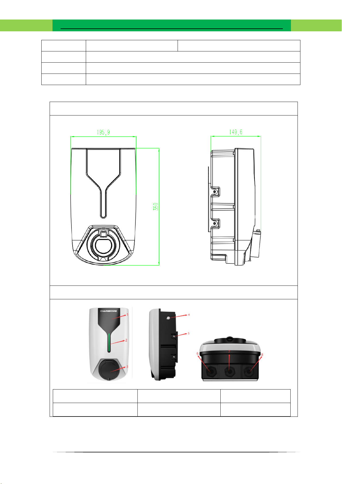
2.2 PHYSICAL DIMENSION .............................................................................................................................................................. 4
2.3 TECHNICAL PARAMETER ........................................................................................................................................................... 6
2.4 FEATURES........................................................................................................................................................................... 7
3.SYSTEM STRUCTURE .................................................................................................................................................... 9
3.1 ELECTRIC............................................................................................................................................................................... 9
3.2COMMUNICATION ................................................................................................................................................................... 9
4.INSTALL.......................................................................................................................................................................11
4.1INSTRUCTION........................................................................................................................................................................ 11
4.2 PREPARE............................................................................................................................................................................. 11
4.3INSTALLATION NOTES ............................................................................................................................................................ 13
5.OPERATION DEBUGGING ............................................................................................................................................15
5.1INSTRUCTIONS...................................................................................................................................................................... 15
6.AFTER-SALES SERVICE .................................................................................................................................................17
6.1AFTER-SALES SERVICE............................................................................................................................................................. 17
6.2DISCLAIMER......................................................................................................................................................................... 17
6.3MAINTENANCE...................................................................................................................................................................... 18
7.APPENDIX ...................................................................................................................................................................19
7.1 INDICATOR STATUS DESCRIPTION: ............................................................................................................................................ 19
7.2 GENERAL TROUBLESHOOTING INSTRUCTIONS............................................................................................................................. 19
7.3 TOXIC AND HAZARDOUS SUBSTANCES OR ELEMENTS IDENTIFICATION TABLE (ROHS) ........................................................................ 21

Nanjing PowerCore Tech Co., Ltd
1
1.SAFETY PRECAUTIONS
1.1SAFETY PRECAUTIONS
Before starting the operation, please read the operation instructions and precautions carefully to reduce the
occurrence of accidents. The "CAUTION, WARNING, DANGER" items in the product and product manual do not
represent all the safety precautions to be followed, but only serve as a supplement to various operational safety
precautions.
When operating the company's products and equipment, you must abide by the safety regulations of the relevant
industry, and strictly abide by the relevant equipment precautions and special safety instructions provided by Nanjing
PowerCore Technology Co., Ltd.
1.2IDENTIFICATION DESCRIPTION
Indicates an operation or situation where extreme care must be taken with
hazardous voltages.
Important safety information, where extreme caution must be exercised or in
situations.
Indicates a burn hazard from a hot area or an area with hot parts.
Protective earth connection point.
Alternating current.
Indicates that the action described must be performed using employer-supplied
clothing and/or personal protective equipment.
1.3ELECTRICAL SAFETY
HIGH VOLTAGE

AC Wallbox series
2
When the power supply system is running, some parts have high voltage, and
direct contact or indirect contact with these parts through non-insulated objects will
bring fatal danger.
Construction operations on high-voltage lines may cause fire or electric shock
accidents. The installation and routing of AC cables must comply with local laws and
regulations. Only personnel qualified for high voltage and alternating current work
can perform various high voltage operations.
The installation of AC power equipment must comply with the safety regulations of the relevant industry,
and the personnel who install the AC equipment must be qualified for high voltage, alternating current and other
operations.
It is strictly forbidden to wear watches, bracelets, rings and other conductive objects on the wrist during
operation.
When the cabinet is found to be wet or wet, please turn off the power immediately. When operating in
a humid environment, moisture should be strictly prevented from entering the equipment.
On the switches and buttons that are not allowed to be operated during the installation process, the
prohibition of operation signs must be hung up.
TOOL
Special tools must be used when carrying out various operations with high
voltage and alternating current.
THUNDERSTORM
It is strictly forbidden to conduct high voltage and alternating current in
thunderstorm weather.
During thunderstorms, strong electromagnetic fields are generated in the atmosphere. Therefore, in order to avoid
lightning damage to the equipment, it is necessary to do a good grounding of the equipment in time.
STATIC ELECTRICITY
Static electricity generated by the human body can damage static-sensitive
components on circuit boards, such as large-scale integrated circuits (ICs). Before
touching the device, holding the plug-in board, circuit board, IC chip, etc., in order to
prevent the static electricity of the human body from damaging the sensitive
components, you must wear an anti-static wristband, and the other end of the anti-
static wristband should be well grounded.
SHORT CIRCUIT

AC Wallbox series
3
It is strictly forbidden to short-circuit the power distribution of the power system
or short-circuit the non-grounded pole to the ground during operation, which will
cause equipment burnout and personal safety hazards.
The polarity of cables and interface terminals must be strictly checked during live work.
The power distribution operation space is compact, and the operation space should be carefully selected
before any operation.
Operation must use insulated tools.
When operating with electricity, you must pay attention to keeping the hands, wrists and arms in a
tense state to prevent accidents caused by excessive tool or human activity when the tool slips.
1.4 OTHERS
SHARP CORNERS OF OBJECTS
When handling the device by hand, wear protective gloves to
prevent cuts from sharp objects.
POWER CABLE
Before connecting cables, verify that the cable labels are
correct.
SIGNAL LINE
Signal cables should be bound separately from power cables,
and the binding spacing should be at least 15mm.

AC Wallbox series
4
2.PRODUCT DESCRIPTION
2.1SERIAL NUMBER DESCRIPTION
AC00
6
T1
11
A01
PC
ROU012003000
2
1
2
3
4
5
6
6
PILE ID NUMBER
ROU01 2003 0002 - CUSTOMER ROMARIA 01,
MADE IN MARCH 2020, PILE 0002, HERE FOUR
DIGITS IN DECIMAL.
5
MANUFACTURER
4
BOM VERSION:
3
CHARGING POWER:
7: AC CHARGER RATED POWER 7KW
9: AC CHARGER RATED POWER 9KW
11: AC CHARGER RATED POWER 11KW
22: AC CHARGER RATED POWER 22KW
2
CHARGING STANDARD:
T2: TYPE2 AC CABLE VERSION
T2S: TYPE2 AC SOCKET VERSION
T1: TYPE1 AC CABLE VERSION
1
PRODUCT NUMBER:
AC006 - PLASTIC SHELL AC CHARGER
2.2 PHYSICAL DIMENSION
Application
scenarios
Parking lot/family garage/parking space
Material
Plastic cabinet
Installation
Wall-mounted
Cable layout
Bottom entry
Weight
Socket
4.1KG(N.W)

AC Wallbox series
5
cable
7.3KG(N.W)
Cable length
≥5m(CABLE Model)
Socket
Type1 or Type2(SINGLE OUTPUT)
Cabinet size
195.9x149.6x350(mm)
Dimensions
Appearance drawing
1. Film stickers
2. Indicator light
3. Socket
4. Emergency stop
5. Backplane fixing screws
6. Cable entry hole

AC Wallbox series
6
2.3 TECHNICAL PARAMETER
Parameter
AC006(type2)
AC006(type1)
7. Network cable hole
(optional network cable
interface)
8. Cable wire hole (optional
charging gun wire)

AC Wallbox series
7
Input voltage
230VAC(1P+N+PE)±10%
400VAC(3P+N+PE)±10%
230VAC(L1+L2+PE)±10%
Input
frequency
50Hz/60Hz
50Hz/60Hz
Rated power
7kW(1p)/11kW(3p)/22kW(3p)
7kW/9kW/11kW(L1-L2)
Measurement
accuracy
≤±1%
≤±1%
Output
voltage
Same as input voltage
Output
current
SINGLE PHASE:32A
THREE PHASE:16A/32A
32A/40A/48A
User
Interface
Emergency stop button, led indicator, card
reader (optional)
Emergency stop button, led indicator, card
reader (optional)
charging
method
Plug and charge, APP (timed start and
stop),
Swipe card (optional)
Plug and charge, APP (timed start and
stop),
Swipe card (optional)
interface
standard
Type2 (Socket/Cable)
Type1
The internet
2.4G WiFi/Ethernet
2.4G WiFi/Ethernet
ocpp
OCPP 1.6J
OCPP 1.6J
Application
site
Indoor/Outdoor
Indoor/Outdoor
Operating
temperature
-20℃~ +50℃
-20℃~ +50℃
Working
humidity
5% ~ 95% no frost
5% ~ 95% no frost
Altitude
<2000m
<2000m
Protection
class
IP54
IP54
Cooling
method
Free cooling
Free cooling
Leakage
detection
30mA AC, 6mA DC
CCID20
2.4 FEATURES

AC Wallbox series
8
AC006 AC charger has modern appearance design and user-friendly operation experience. It is
mainly used for household use. It is an intelligent IoT charger. It can be used for Bluetooth
distribution network through mobile APP, and it is easy to start and stop the charging pile
anytime, anywhere. More functions are all in the APP.
⚫Safety
➢Multiple hardware protection functions
•Overcurrent protection (software protection)
•Emergency stop protection
•Leakage protection (software protection)
➢Comprehensive software protection function, which can provide multiple protections.
➢IP54
⚫Intelligent
➢Terminal charging pile and cloud OCPP platform intelligent IOT
➢Start or stop the charging pile regularly
➢Remote diagnosis, remote upgrade
➢Support Type1 and Type2 standards (choose one of two)
➢Support OCPP1.6+ (later can be directly upgraded to 2.0)
⚫Convenient
➢Wireless communication
➢Support energy demand corresponding, plug and charge expansion function
⚫Optional function
➢Home load balancing
➢Swipe card function

AC Wallbox series
9
3.SYSTEM STRUCTURE
3.1 ELECTRIC
Transformer-Switch-Charger-Car(Type2)
电网10kV
TN-C-S
10kV/400V
3
TN-S AC
Transformer-Switch-Charger-Car(Type1)
3.2COMMUNICATION
Communication Architecture Diagram

AC Wallbox series
10

AC Wallbox series
11
4.INSTALL
4.1INSTRUCTION
4.1.1SAFETY INSTRUCTIONS
The working voltage and current inside the charging system are high. In order to ensure personal safety, the following
regulations should be observed at all times:
⚫Only personnel who have received training on the charging system and have sufficient knowledge of the charging
system can install it. During installation, the safety precautions and local safety regulations following the catalog should
always be followed.
⚫If you want to operate inside the charging system, make sure that the charging system is not charged. The mains
input to the charging system must be disconnected.
⚫The wiring of power distribution cables should be reasonable and protected to avoid accidental contact when
operating the power supply equipment.
4.1.2OPEN BOX TO CHECK
Only after the goods arrive at the installation site, the packing box can be unpacked for inspection. When inspecting the
goods, first unpack the packing box with the packing list storage box, take out the packing list, and check item by item against
the packing list. Secondly, check the number and serial number of the box identification, the correctness of the equipment
packing, the number and type of accessories and the integrity of the items.
After the product arrives, confirm whether the package is damaged and whether the label is complete and correct. If
there is any abnormality, please notify the carrier immediately, and take a photo to collect evidence. You can sign and indicate
it first, and immediately contact the manufacturer to discuss and deal with it.
⚫According to the packing list, check whether the product accessories and accompanying documents are complete
(refer to the shipping list), and properly keep the accessories and documents.
⚫Visual inspection to ensure that the product is free of abnormal conditions such as collision, scratches, cracks,
dents, rust, damage, peeling paint surface, etc.
⚫Check whether the equipment has abnormal conditions such as crushing, rusting, and damage.
⚫Sign and receive documents, record the situation, save the documents in time, scan and distribute or hand them
over to related parties.
⚫See the accompanying documents for the packing list.
4.2 PREPARE
4.2.1TOOL PREPARE
UNIVERSAL TOOL
NAME
DESCRIPTION
QTY

AC Wallbox series
12
ELECTRIC IMPACT DRILL
DRILLING
1PCS
IMPACT DRILL (Ø 6)
DRILLING
1PCS
TAPE MEASURE (5M)
MEASUREMENT
1PCS
LEVEL
MEASUREMENT
1PCS
1/PHILLIPS SCREWDRIVER
UNPACKING / ENCLOSURE / WIRING
1PCS EACH
CABLE STRIPPER
STRIP OFF THE INSULATING JACKET
1PCS
DIAGONAL PLIERS
CUT THE CABLE
1PCS
INSULATION TAPE
INSULATION TAPE INSULATION WRAP CONNECTION
1PCS
PERSONAL PROTECTIVE EQUIPMENT
ENSURE OPERATOR SAFETY AND HEALTH
1PCS
4.2.2VENUE SPACE REQUIREMENTS
This model AC006 wall-mounted AC charger can be configured with Type1 or Type2 charging cable or socket. The system
can be installed outdoors (for safety reasons, it should not be used in rain or snow if standing water reaches the charging
point connector).
In order to ensure the safe and reliable operation of the equipment, ventilation and maintenance requirements,
sufficient installation space should be reserved.
4.2.3CIVIL/FOUNDATION REQUIREMENTS
When using the back panel to hang on the wall, you must ensure that the wall has a certain level of flatness and strength
to ensure that the charging pile is installed securely.
The installation surface is pre-buried with 4 M6*30mm expansion screw holes.
➢The back panel is hung on a solid wall and can be fixed with expansion screws
Backplane bracket

AC Wallbox series
13
4.3INSTALLATION NOTES
4.3.1CABINET INSTALLATION INSTRUCTIONS
1)FIXED IN PLACE
a)Fix the base to the wall
•Carefully and slowly descend, placing the charging station precisely in place
•Take care to ensure that the cables have been exposed along the gland to the inside of the cabinet
•Take care to ensure that the cabinet holes are aligned with the bolt holes
•Tighten these retaining nuts
b) keep the device upright
Place the charger on the hanger and lock the charger.

AC Wallbox series
14
4.3.2ELECTRICAL REQUIREMENTS
Cable type: TN-C-S/TN-S, confirm whether it needs to be shielded according to local laws or regulations
⚫If there is a shielding layer, both ends of the shielding network must be connected to the PE safety ground
wire.
⚫Cable diameter requirements are determined by the contractor or electrical engineer based on power,
distance and industry standards, or recommended requirements:
➢Using ZR-YJV-multi-core sheathed power cable
➢The voltage class is 450/750V or higher voltage class
➢At least a temperature resistance level of 90 °C should be achieved.
⚫It is recommended that the power distribution input wire diameter of the charging pile should not be lower than
the following recommended values, and should have independent circuit breakers and leakage protection (the
following table shows the current-carrying capacity of YJV22 (armoured) cables directly applied in the soil at 25°C as
a reference , according to the actual cable material and laying method to determine the specific wire diameter)
Power(kW)
7(TYPE2)
11(TYPE1)
11(TYPE2)
22(TYPE2)
Input voltage(V)
220V
240(L-L)
400
400
Input current(A)
32
48
16
32
Recommended cable
diameter
≥6mm2
≥8AWG
≥4mm2
≥6mm2
4.3.3INTERNET CONNECTION REQUIREMENTS
Wireless WIFI access is used by default. It is necessary to confirm that the local signal strength is sufficient and stable,
otherwise a signal amplifier needs to be installed.
If there is no local WIFI communication signal, a standard wired Internet connection can be used. The wired connection
must meet the following requirements:
⚫RJ45 Ethernet
➢Network cable type: Category 5 or above, 8P+PE, shielded cable
➢Recommended line length within 75m, more than 75m line length, need customized engineering solution
⚫Minimum bandwidth required
➢Uplink:128 kbps

AC Wallbox series
15
➢Downlink:4 Mbps
⚫Required connection reliability: 99.9%
FOR SPECIAL CONFIGURATION, PLEASE CONTACT OUR COMPANY
4.3.4CONNECT THE POWER CABLE
Note: Before making electrical connections, place all switches, fuses, etc. in the OFF position
When installed, the charging pile needs to be connected with an additional TYPEB grade leakage protector
⚫CONNECT THE GROUNDING CABLE
The charging system adopts the common grounding method, and uses the grounding cable to
connect the grounding copper bar of the charging integrated cabinet and the main grounding bar
of the engineering installation.
⚫CONNECT AC INPUT
➢The AC input cable is wired from the user's power distribution switch, and the cable
is connected to the output terminal of the user's switch when the power is finally ready.
The user distribution switch should have protection devices such as overcurrent, short
circuit, lightning strike, etc. The capacity of the distribution switch is recommended
not to be less than 1.5 times the actual load capacity.
➢The L1 phase, L2 phase, L3 phase and N neutral cable of the AC input cable should
use brown, black, gray and blue cables respectively. If the cable has only one color, it
is necessary to paste the wire number mark or mark the two ends of the cable with insulating
tapes of different colors.
➢The cables are not allowed to be broken, damaged or scratched.
The AC input can be introduced through the charging pile junction box and connected to the
corresponding binding posts (terminals) in sequence.
Phase/neutral stud/identification diagram (take a single item as an example)
5.OPERATION DEBUGGING
5.1INSTRUCTIONS
5.1.1POWER-ON PROCESS

AC Wallbox series
16
Ensure that the charging pile is installed stably, the wires are wired correctly and reliably,
and the charging pile can be powered on. After the charging pile is powered on, the indicator
light should be flashing blue or always on. Please refer to the appendix below for the
description of the status of the indicator light: Description of the status of the indicator
light.
5.1.2CHARGING OPERATION
There are three ways to start charging: plug and play, mobile phone APP, and credit card
charging (optional).
Before charging, please make sure that the charging cable is firmly inserted into the charging
port of the vehicle.
If you need to use the APP to start charging, please use the APP to scan the QR code on the
side of the charging pile when using it for the first time, and turn on the Bluetooth of the
mobile phone for Bluetooth networking. After the networking is completed, follow the APP
prompts to charge.
Click the charging pile information in the APP to obtain the output capability of the charging
pile and the information of the running status. When the running status is an alarm, charging
cannot be performed. It needs to be charged after troubleshooting according to the fault
identification or common fault problems.
When the set value is reached or the vehicle sends a stop command, the charging pile
automatically stops charging.
5.1.3EMERGENCY OPERATION
The emergency stop alarm is not part of the normal charging operation. Only when there is an abnormality or
misoperation, please refer to this part.
Emergency stop: only when an emergency occurs, press the "emergency stop button" on the side, and the system
will cut off the output power.
Reset by pressing the emergency stop button again!
Do not use the "emergency stop button" for normal shutdown.
Emergency stop button + location map

AC Wallbox series
17
5.1.4FORCED PULL-OUT RECOVERY
It is forbidden to forcibly unplug the charging connector during the charging process!
⚫If the normal stop operation fails to stop, it is recommended to press the emergency stop button.
⚫Then unlock it manually, prohibiting the forced drawing of the connector.
6.AFTER-SALES SERVICE
6.1AFTER-SALES SERVICE
1.Two-year warranty on all parts.
2.During this period, if any parts are damaged excluding non-quality factor damage, we will
provide free accessories for customers to replace by themselves. Does not include non-quality
factor damage.
3.One-on-one technical engineer support.
6.2DISCLAIMER
The product equipment needs to be used normally within a certain range of conditions. If one of the following
conditions causes an accident or damage, the company will not be responsible for it.
⚫All damage caused by human factors and use in abnormal working environment
⚫Failures and damages caused by not using the instructions or using the environment in accordance with
the instructions
⚫Damage caused by poor transportation after delivery
⚫Normal wear, abrasion, cracking and impregnation, etc.
⚫Products that do not belong to our company (such as fakes)
⚫Without the consent of the company, disassemble, repair, modify the product, etc.

AC Wallbox series
18
⚫Damage caused by other force majeure (such as flood, fire, lightning strike, typhoon, earthquake,
abnormal voltage)
⚫Exceeding the service life is not within the scope of our warranty
6.3MAINTENANCE
6.3.1 ON-SITE MAINTENANCE
This device is an IoT-type charger with intelligent functions such as pre-charging self-check,
daily regular self-check, online monitoring of electrical components and operating parameters.
⚫Normal operation, only daily cleaning and maintenance, no need for repair and
maintenance
⚫If the operation is abnormal, please refer to Appendix: Operation Instructions for
General Troubleshooting, and contact the Neckray Customer Service Center or local supplier in
time
6.3.2 REMOTE MAINTENANCE
The charger has the function of connecting with the device cloud platform to monitor the
status of the charger in real time. When connected to the PowerCore platform, the platform
can provide complete remote diagnosis, remote service, and remote upgrade services, and can
timely discover and locate actual problems in the actual operation process, and provide
corresponding solutions accordingly to help the operation center realize remote services. ,
can remotely upgrade the software, solve the problems of end users, and realize unattended
operation.
⚫The system conducts self-checks every day, and reports any abnormality to the
background
⚫If the operation is abnormal, please contact the customer service center or local
supplier in time
⚫Lengcare service engineers can query logs, update configurations and programs, and
implement remote maintenance actions such as remote management, diagnosis, configuration,
and upgrade.
This manual suits for next models
1
Table of contents
Popular Batteries Charger manuals by other brands

Silvercrest
Silvercrest SQWC A2 Operation and safety notes

CO/Tech
CO/Tech KF15L-18V2500G-UK Original instructions

Power-Sonic
Power-Sonic Power-Gel Series DCG12-65 Specifications

Clear-Com
Clear-Com AC60 quick start guide

Lamarche
Lamarche A75D Installation and operation manual

Power Fist
Power Fist 9051467 instructions