Smappee EV Base User manual

English – Version 1.0 – September 2020
Smappee EV Base
Installation manual

Smappee EV Base – Installation manual - English
2
Table of contents
1. Introduction ...................................................................................................... 3
2. Safety instructions ............................................................................................ 4
3. Components ..................................................................................................... 6
4. Technical specifications .................................................................................... 7
5. Preparing the installation ................................................................................. 8
6. Installation and activation .............................................................................. 11
7. Using the EV Base ........................................................................................... 17
8. Declaration of conformity .............................................................................. 20

Smappee EV Base – Installation manual - English
3
1. Introduction
Thank you for purchasing this Smappee EV Base charging station for electric vehicles, the smartest
charging station for businesses.
This installation and user manual tells you how to install and use the Smappee EV Base. We advise
you to read the contents of this manual carefully, to ensure a safe and proper installation and enable
you to use all the advanced features of this product to the full.
Support
Only qualified electricians or equivalent may install the Smappee EV Base. If you have any questions,
please contact your service partner.
Please have the following information ready to hand to speed up the process: Article number and
serial number which you can find on the identification label of the charging station.
Should your local distributor be unable to help you, or you have a suggestion for us, you can contact
Smappee at: [email protected].
Smappee n.v.
Evolis 104
8530 Harelbeke
Belgium

Smappee EV Base – Installation manual - English
4
2. Safety instructions
Safety warning
Fully read and follow the safety instructions below before you install, service or use your Smappee
EV Base. The installer must ensure that the charging station is installed in accordance with the
relevant national and local regulations.
Carrying out activities on this charging station without the relevant knowledge and qualifications can
lead to serious accidents and death. Only carry out tasks for which you are qualified and have been
fully instructed.
Incorrect installation, repairs or modifications can result in danger to the user and may void the
warranty and liability.
Safety precautions
CAUTION: Risk of electric shock.
CAUTION: Refer to the accompanying documentation whenever you see this symbol.
Please observe the following safety precautions to avoid potential electric shock, fire, or personal
injury:
• Use this charging station only for its intended purpose.
• Switch off electrical power supply to your charging station before installation or maintenance
work.
• Do not use the charging station if damaged / defective.
• Do not immerse the charging station in water or any other liquids.
• Do not expose the charging station to heat, flame or extreme cold.
• Do not attempt to open, repair, or service any parts. Contact Smappee or your service partner
for further information.
• Only use the charging station under the specified operating conditions.
• Do not allow children to operate a charging station.
• When a charging station is in use, adult supervision of any children present is required.
• While charging the charging cable must be completely unwound and connected to the electric
car without overlapping loops. This to avoid the risk of overheating the charging cable.
Maintenance
• Observe the maintenance schedule.
• Clean the outside only with a dry, clean cloth.
• Do not use abrasive agents or solvents.

Smappee EV Base – Installation manual - English
5
Keeping order
• After charging store the charging cable properly so it does not present a tripping hazard.
• Make sure the charging cable cannot become damaged (kinked, compressed or driven over).
• Do not place any objects on the charging station.
Transport and storage
• Disconnect electrical power supply before removing the charging station for storage or
relocation.
• Only transport and store the charging station in its original packaging. No liability for damage
incurred will be accepted if the charging station is transported in non-standard packaging.
• Store the charging station in a dry environment within the temperature range specified in the
technical specifications.

Smappee EV Base – Installation manual - English
6
3. Components
Components included
1. 1 x Smappee EV Base unit
2. 1 x Floor plate
3. 1 x Plastic bag containing installation material (4 x concrete anchors, 4 x washers)
Identification label
The identification label of your charging station is located under the top cover of connector 1.
1. Manufacturer
2. Article number
3. Rating
4. Serial number
5. Manufacturing date
6. Degree of protection
7. QR code containing article number and serial number

Smappee EV Base – Installation manual - English
7
4. Technical specifications
Feature
Description
Technical features
Charging capacity per connector
Single or triple phase, 3.7 to 22 kW per connector
Number of connectors
2 x Type 2
Output power per connector
1-phase or 3-phase, 230 V – 400 V, 16 A or 32 A
Charge mode
Mode 3 (IEC 61851)
Connection case
2 x Case C (Fixed cable)
Integrated Residual Current Monitor
Rated operating residual current detection : 6 mA DC / 30
mA AC per connector
Interfaces & Connectivity
Information status
RGB LED
Session activation
Plug & Charge, Scan QR code, Swipe RFID card
Connectivity
Wi-Fi 2.4 GHz, Ethernet 100BASE-T, LTE CAT M1 or NB2
Communication protocol
OCPP 1.6 JSON
Certifications and Standards
Product certification
CE, see declaration of conformity in chapter 8.
Standards
IEC 61851-1 (2017)
Environment
Enclosure material
Aluminium (structure), Outdoor high pressure laminate
(casing)
Enclosure rating
IP55 / IK10
Enclosure standard colours
RAL9016 (star white) + RAL7021 (black grey)
Operating temperature
-25 °C to 60 °C
Storage temperature
-25 °C to 80 °C
Relative humidity
0 % - 95 %, non-condensing
Maximum installation altitude
0 – 2.000 m
Physical properties
Dimensions
1200 x 600 x 150 mm
Weight
20 kg (28 kg incl. 2 cables), excluding packaging
Charging cable length
2 x 2500 mm
Mounting method
Floor / Ground

Smappee EV Base – Installation manual - English
8
5. Preparing the installation
The first step is to prepare the physical installation of the EV Base as described in this chapter.
Installation prerequisites
• Calculate the existing electrical load to find the maximum operating current for the charging
station installation. The Smappee EV Base is equipped with 2 connectors which need to be
powered individually. Note that with the Smappee Overload functionality more charging
stations or the total maximum operating current can be higher than the physical installation
allows.
• Determine the voltage drop over the distance from the power supply panel to the charging
station installation. The voltage drop must not exceed 5 %. It is advised that the maximum
voltage drop be 3 %. The maximum wire gauge that can be fitted is 10 mm². Local regulations
may be applicable and can vary depending upon the region or country.
• Obtain all necessary permits from the relevant local authority.
• Refer to local wiring regulations to select the conductor sizes and use only copper conductors.
• Make sure that the installation area of the charging station is adequate for usability and
ventilation purposes.
• Use the correct tools and provide sufficient material resources and protection measures.
• Make sure that there is an internet connection available for each EV Base (1 per unit).
Depending on your Smappee EV Base type, either foresee an Ethernet cable (preferred) or Wi-
Fi at the location of the EV Base or a reliable 4G cellular network reception.
Route power supply
• The appropriate wire gauge of the supply cable depends on the power rating and distance
between the meter cabinet and the charging station. The voltage drop must not exceed 5%. It
is advisable to have a maximum voltage drop of 3%. The maximum wire gauge that can be
fitted is 10 mm².
• Route the power supply cables to the position where the charging station will be installed
together with an Ethernet cable for the internet connection (if applicable).
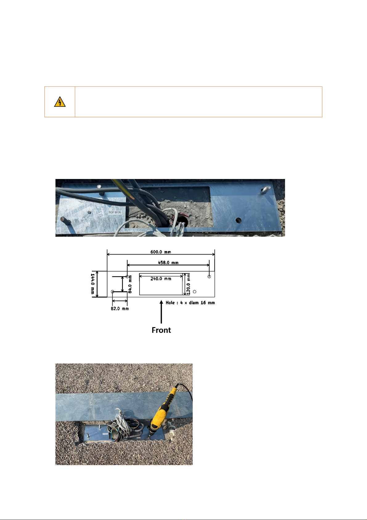
• Make sure the power supply cables are positioned through central position of the floor plate
recess.
• Make sure that there is at least 60 cm available out of the ground.
Both power lines enter the station via the floor plate.
If an Ethernet cable is used for the internet connection, this also enters the charging
station via the floor plate.

Smappee EV Base – Installation manual - English
9
The maximum power rating for each connector is specified in the table below.
Power per connector
Connection
Input current
Output current
3.7 kW
1-phase
2 x 16 A
2 x 16 A
11 kW
3-phase
2 x 16 A
2 x 16 A
22 kW
3-phase
2 x 32 A
2 x 32 A
Prepare the mounting foundation
The Smappee EV Base is designed to be installed at ground level without the need for a separate
mount.
A stable and level ground needs to be prepared in advance. We advise a levelled concrete
foundation at ground level. It is also possible to have the foundation a little lower than ground level.
This allows the anchors to be masked and the EV Base to be integrated in the surrounding soil.
Depending on the subsoil, the size may vary. Please refer to the technical specifications of size and
weight to determine and construct a solid foundation for the EV Base.
Make sure the power supply cables are positioned through central position of the floor plate recess.

Smappee EV Base – Installation manual - English
10
Tools
(not included)
Screwdrivers and a 2.5mm Hex screwdriver
Multi meter and earth ground meter
Wire stripper and cutter.
Needle-nose pliers.
Ferrules crimper, for stranded power supply cables
Drill and rock drill diameter 12 mm.
18 mm socket wrench with ratchet handle
Hammer
Supplies
(included)
4 x concrete anchors (Ø 12 mm x 100 mm)
4 x washers (Ø 50 mm)
Supplies
(not included)
Ethernet cable or RJ45 connector for wired communication.
Power supply cables
Ferrules (10 mm²), for stranded power supply cables
Smappee EV Base – Installation manual - English
11
6. Installation and activation
This procedure describes the required steps for the physical installation of the EV Base.
CAUTION: Make sure it is not possible to connect the electric current during
installation. Put up caution tape and warning signs to mark the work areas. Make sure
no unauthorised people can enter the work areas.
Mount the anchors
a. Use the floor plate to mark the position of the anchors on the pre-prepared concrete
foundation. Make sure the top side label of the floor plate is facing upwards. The power supply
cables should go through the central recess of the base plate.
b. Drill 4 holes of 12 mm diameter through the slots to a depth of 70 mm. Insert the supplied
concrete anchors. Make sure that there is approx. 3 cm of threaded wire visible above ground
level.

Smappee EV Base – Installation manual - English
12
c. Mount the floor plate over the anchors and make sure it is level in both directions. If not, tilt the
floor plate until it becomes level.
To tilt the floor plate, insert large washers below the floor plate until it becomes level.
Place the EV Base in position
a. Remove the backplate of the EV base and position this on the floor plate.

Smappee EV Base – Installation manual - English
13
b. Position the one of the four supplied large washers (Ø 50 mm) over each of the 4 screw threads
(anchors).
c. Place the four nuts and hand tighten.
Do NOT torque the four nuts yet. This is done in the last step of the installation, when the
back cover of the EV Base is in place.
Power supply connection
a. Cut both the power supply cables to adequate length and add the ferrules to each conductor.
b. Measure the resistance of the grounding circuit and make sure that it is within acceptable limits.
If necessary, install a grounding point closer to the charging station.
c. Connect each supply cable to the correct terminal block.

Smappee EV Base – Installation manual - English
14
Phase rotation
To avoid overloading the first phase with one-phase electric vehicles, phase rotation is
recommended. We recommend rotating the phases as shown in the table below.
EV Base
Connector
Phase mapping
EV Base 1
Connector 1
L3 – L2 – L1 – N (as indicated on the label)
Connector 2
L1 – L3 – L2 – N
EV Base 2
Connector 1
L2 – L1 – L3 – N
Connector 2
L3 – L2 – L1 – N (as indicated on the label)
EV Base 3
Connector 1
L1 – L3 – L2 – N
Connector 2
L2 – L1 – L3 – N
And continue with this pattern for other EV Base units.
When phase rotation is applied on a connector adjust the configuration in the Smappee
Dashboard.
Internet connectivity
a. Internet connectivity: If Ethernet cable is used for internet connection, mount the Ethernet cable
in the Smappee Connect (bottom). Cut the Ethernet cable to the appropriate length and mount
an RJ45 connector (not supplied).
Switching on the EV Base
a. Check all connections are secure and power-up both power supplies of the EV base.
b. Check the status LEDs:
o Both charge controllers
o Both RCM
o Connect – Blue flashing
o Ambient light is illuminated with a white fixed light
Activation
This procedure is done with the Smappee Energy Monitor mobile app. You can download this from
the Apple App Store for iOS or the Google Play store for Android phones.
The Smappee App will guide you through the various steps to fill in all the required information.

Smappee EV Base – Installation manual - English
15
•
Log in to the Smappee App with the corresponding Smappee username or create a new user
account.
•
Install a Smappee EV Base
•
Follow the steps shown in the mobile app.
Multiple charging stations can be installed at a single location. To add a new charging
station in the mobile app, go to Settings > Your Smappee charging stations
The settings of your charging station can be adjusted in the Smappee Mobile app or
Dashboard.
• Smappee Mobile App: Name, Minimum and maximum current per connector,
Charging speed per connector and LED brightness
• Dashboard: Name, Minimum and Maximum current per connector, Phase
assignment per connector, Charging speed per connector and LED brightness
For overload protection or optimised self-sufficiency additional Smappee Infinity
components must be installed to measure the Grid and Solar, Battery, other submetering
if applicable.
Closure
a. Mount the back plate into position and tighten the screws.
If the screw holes do not align, loosen the anchor nuts to eliminate any torsion in the
frame.

Smappee EV Base – Installation manual - English
16
b. Tighten the anchor nuts with a socket wrench.
c. Finish off by using the preferred top coat.
Smappee EV Base – Installation manual - English
17
7. Using the EV Base
There are three ways of charging using a Smappee EV Base:
1. Plug & Charge: Simply insert the connector in the EV and start charging.
2. Scan & Charge: Insert the connector, scan the QR code in the Smappee app and start
charging.
3. Swipe & Charge: Insert the connector, swipe your RFID card and start charging.
Below you can find the different charging sequences.
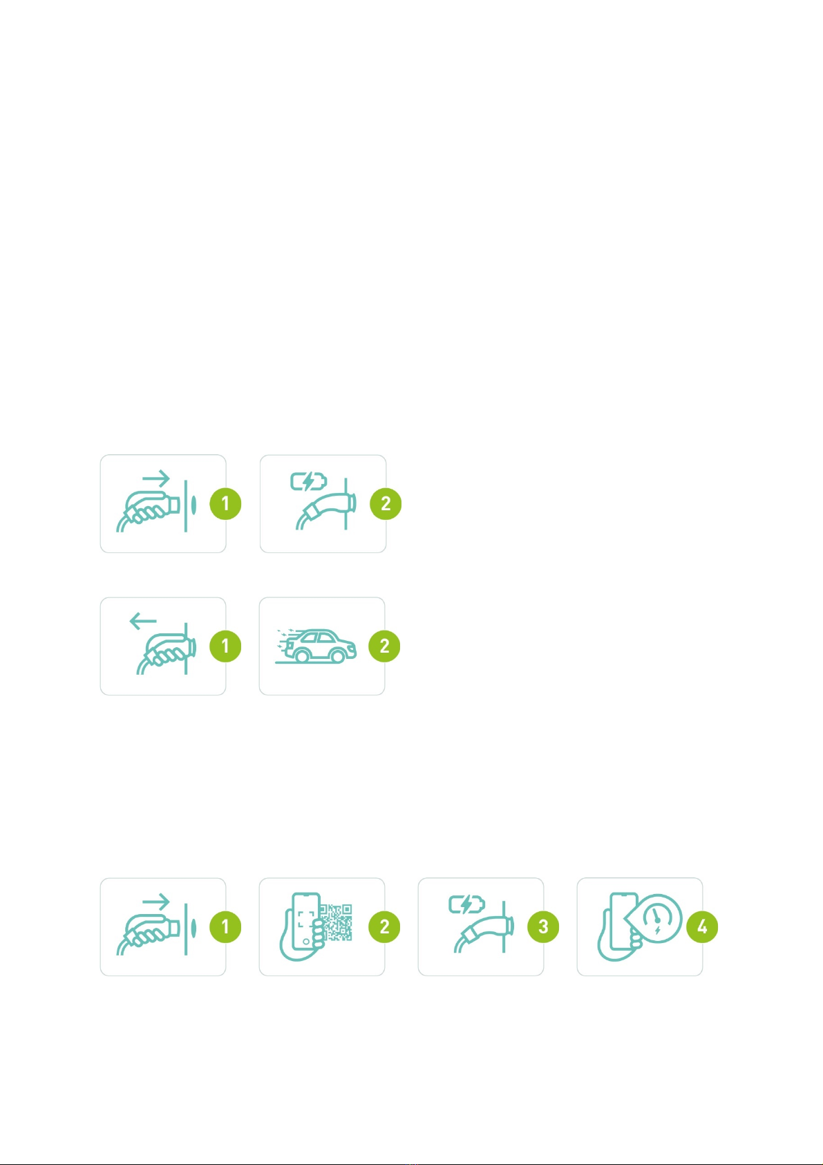
Plug & Charge
This is a general authorisation without a charge card or without a QR code. To start charging, simply
connect your EV with the Smappee EV Base. If you want to stop charging, simply disconnect the
cable from your EV.
Start charging
Stop charging
Scan & Charge
If you want to authorise via a QR code, you will first have to connect your EV with the Smappee EV
Base. Then, you will have to scan the QR code found on the same side as your EV with your smart
phone and your charging session will commence. To stop charging, either go the Smappee app, your
car charging app or simply disconnect your EV from the Smappee EV Base.
Start charging

Smappee EV Base – Installation manual - English
18
Stop charging
Swipe & Charge
If you want to authorise your charging session with an eMSP provider, you will first have to connect
your EV with the Smappee EV Base. Then, you will have to scan your RFID card which can be done by
holding it directly above the Smappee EV Base. You will hear a confirmation tone when your card is
successfully scanned. If your charge card is approved, you will hear an affirmative tone and a
charging session will commence. To stop charging, simply disconnect your EV from the Smappee EV
Base.
Start charging
Stop charging

Smappee EV Base – Installation manual - English
19
LED status
LED colour
LED status
Meaning
Action of the user
White fixed
The Smappee EV Base is
available.
Connect your EV with the
Smappee EV Base.
Blue fixed
Your EV is connected with
the Smappee EV Base, but
is not yet charging.
• If using an RFID, scan your
charge card and wait until the
LED turns blue and flashes.
• If using QR codes, scan the QR
code and wait until the LED is
green pulsing.
• If no authorisation is required,
wait until the LED becomes
green pulsing.
Blue flashing
Your RFID card is being
verified.
Wait until the LED is green
pulsing.
Green pulsing
The Smappee EV Base is
charging your EV.
Your EV is being charged.
Green fixed
The EV is now fully
charged.
Disconnect the cable and put it
back in its socket of the Smappee
EV Base.
Red fixed
The Smappee EV Base has
a problem and is now
unavailable.
Check the manual or contact
your supplier for more info and
further steps.
Red flashing
Your charge card is not
authorised.
Contact your charge card
supplier.

Smappee EV Base – Installation manual - English
20
8. Declaration of conformity
We,
smappee nv
Evolis 104
B-8500 Kortrijk
Belgium
following the provision of the following EC Directives:
- 2014/35/EU The Low Voltage Directive
- 2014/30/EU The Electromagnetic Compatibility Directive
- 2014/32/EU Measuring Instrument Directive
- 2011/65/EU RoHS Directive
hereby declare that the product:
smappee EV-Base with subparts:
Smappee Connect (MOD-GW-3), Smappee MID meter, Power Supply Module, Smappee AC Charger
module and auxiliary parts
is in conformity with the applicable requirements of the following documents
* Metering :
EN50470-1 :2006 / EN50470-3 :2006
* Emissions:
(EN61326-1 : 2013)
Radiated Emission: EN 55011:2009 / EN 55032:2015 (Class B)
Conducted Emission: EN 55011:2009 / EN 55032:2015 (Class B)
Harmonic current Emission: EN 61000-3-2:2005 +A1:2008 + A2:2009
Flicker: EN 61000-3-3:2008
* Immunity:
(EN61326-1 : 2013)
ESD : EN 61000-4-2:2008 / EN 61000-4-2 :2009
Radiated immunity : EN 61000-4-3:2006 + A1:2007 + A2: 2010
Power frequency magnetic field: EN 61000-4-8:2009
Voltage dips/interruptions: EN 61000-4-11:2004
Common Mode Immunity: EN 61000-4-6:2008 / EN 61000-4-6:2009
Burst : EN 61000-4-4:2004 / EN 61000-4-4:2012
Surge: EN 61000-4-5:2005 / EN 61000-4-5:2006
* Safety:
Metering Function : IEC 61010-1 Ed 3.0 (2010-06) + A1:2016
AC Charging equipment : IEC 61851-1 (2017) / EN61558-1
Authorized signatory
<Signature of Stefan Grosjean>
Stefan Grosjean
CEO
Other manuals for EV Base
7
Table of contents
Other Smappee Batteries Charger manuals

Smappee
Smappee EV Base User manual

Smappee
Smappee EV Base User manual

Smappee
Smappee EV Wall LITE User manual

Smappee
Smappee EV One Home User manual

Smappee
Smappee EV Base Operator's manual

Smappee
Smappee EV One Home User manual

Smappee
Smappee EV Wall EVWL-332-BR-E-W User manual

Smappee
Smappee EV Base User manual
Popular Batteries Charger manuals by other brands


Powermania
Powermania Turbo M Series Operation manual

Enerdrive
Enerdrive ePOWER Charger EN31220 owner's manual

ATSI
ATSI RMBC64-24D HAWK Operator's manual

Saritek Technical Solutions
Saritek Technical Solutions Alpatronix CX200 user manual

Würth
Würth AL 50-LI Original operating instructions

jcb
jcb JCB-FCH20LI2 Safety and operating manual


