Powercraft BD 501 User manual

%' 501
Drill Press Artikel-Nr.: 425052
Ident-Nr.: 01011

Komponenten / Ersatzteile
Position Artikel-Nr. Beschreibung
1 425052001001 chuck
2 425052001002 Schaft
10 425052001010 Vierkantaufnahme
52 425052001052 table holder

Art.-Nr.: 42.505.23; I-Nr.: 01011
Operating Instructions
Pillar Drill
BD 501

2
Please fold out page 2 - 5.

3
1

4
2 3
4 5
22
23
21
24

5
6
7 8
25
26
Spindle Motor
Pos. U/Min. Pos. U/Min. Pos. U/Min.
Pos. tr/min Pos. tr/min Pos. tr/min
Pos. t/min. Pos. t/min. Pos. t/min.
Pos. r.p.m. Pos. r.p.m. Pos. r.p.m.
Pos. o/min. Pos. o/min. Pos. o/min.
A-4 280 B-4 450 A-3 540
C-4 620 A-2 720 B-3 870
C-2 1550 B-1 1700 C-1 2350

6
1.0. Layout (Fig. 1/2)
1. Machine base
2. Pillar
3. Fixing screw
4. Drill table
5. Clamping screw
6. Machine head
7. V-belt
8. Motor
9. Grip knobs
10. Scroll chuck
11. Spindle
12. Mounting holes
13. Hinged chip guard
15. Tightening screw
16. Screw
17. Clamping screw
18. On button
19. Off button
20. Grub screw
2.0. Items supplied
Pillar drill
Scroll chuck
Drill chuck key
Hinged chip guard
3.0. Proper use
This table drilling machine is designed for drilling
metal, plastic, wood, and similar materials.
Neither food nor materials that present a health
hazard may not be processed with the machine. The
drill chuck is only designed for use with drill bits and
tools with a shaft diameter of 1.5 to 16 mm, and for
cylindrical tool shanks. The device is for adult use
only. The machine is designed for continuous
operation with intermittent load (S6 50 %). Any use
of the machine other than that stipulated in these
operating instructions releases the manufacturer
from all liability and voids all warranty claims.
4.0. Safety information
The pillar drill was designed in such a way so as to
all but eliminate potential hazards when the machine
is properly used. However, there are a few safety
precautions to observe in order to ensure that all
residual hazards are ruled out.
Ensure proper voltage
The voltage must comply with the specifications on
the rating plate.
Use a socket-outlet with earthing contact
The device may only be operated from an outlet with
the properly installed earthing contact.
Extension cable
The cord cross section of an extension cable must
measure at least 1.0 mm_. Always completely
unwind a cable reel prior to use. Check the cable for
defects.
Protection against electrical shock
Keep the device away from moisture. The device
must neither be damp nor be operated in a humid
environment. Prior to every use, check the device
and the mains cable with plug for damage. Avoid
bodily contact with earthed parts e.g. pipes, hot
elements, etc.
Protection against fire and explosion
There are spark producing components inside the
device. Do not use the device in the vicinity of
combustible liquids or gases. Otherwise there is a
risk of fire or explosion.
Handle the device with care
Do not use the cable to pull the plug out of the
socket. Protect the cable from heat, oil and sharp
edges. Keep your tools sharp and clean so that you
can work efficiently and safely. Follow the
maintenance regulations and the instructions for
changing tools.
Wear suitable work clothes and personal
protection equipment
Loose clothing is not suitable, as it can be caught by
moving parts, causing you to become entangled.
Wear a hair net if you have long hair. As a general
rule, jewelry should not be worn when working with
machine tools. Ensure that you wear safety goggles.
Not doing so could result in eye injury.
Keep your work area neat and tidy
Disorder in the work area can easily lead to
accidents. Do not leave any tools, objects, or cable in
the direct vicinity of the work area, as this poses a
tripping hazard! Ensure that there is sufficient
lighting.
GB

7
Watch out for other persons
Watch out for other persons (especially children)
when using the device, and keep them away from
your work area. Do not let anyone touch the device
or the power cable.
Store the tools in a safe location
Store unused devices in a dry, locked location that is
out of the reach of children.
Avoid overloading the device
Operate the device only within the specified output
range. Do not use any low-powered machines for
heavy duty work. Do not use tools to perform work
for which they were not intended.
Maintain a steady foothold
Ensure that you maintain a steady foothold while
working. Avoid abnormal body positions and always
keep your balance.
Pull out the mains plug
Pull out the mains plug when not using the tool, prior
to maintenance, and when changing the drill bit.
Avoid unintentional start-up
Ensure that switch is turned off when plugging the
plug into the socket.
Keep an eye on your work
Always keep an eye on your machine and the object
you are working on. Never use the machine when
you are not concentrating or are distracted. Never
use the machine when you are under the influence of
alcohol or are taking medication.
Check the tool for damage
Before using the tool, safety devices and any slightly
damaged parts must be carefully checked to ensure
that they are in good working order. Visually examine
the tool’s power cable on a regular basis. All parts
must be correctly assembled and meet all the
conditions required to ensure proper operation.
Unless otherwise specified in the operating
instructions, any damaged safety devices and parts
must be properly repaired or replaced by a
professionally recognized workshop. Never use tools
with defective On/Off switches.
Warning! Using any plug-in tools and accessories
other than those specified in these operating
instructions can lead to injury.
Now, please read and follow all steps and
procedures included in the operating
instructions.
5.0. Technical data
Nominal input voltage 230V ~ / 50 Hz
Nominal output 400 Watts
Operating mode S6 50 %
Nominal idle speed 280 - 2,350 min-1
Speed levels 9
Drill chuck mount B 16
Scroll chuck Ø 1.5 - 16 mm
Max. shaft diameter 16 mm
Reach 115 mm
Drill depth 50 mm
Pillar diameter 46 mm
Height 610 mm
Weight approx. 22 kg
Technical and visual enhancements may be made
without prior notice. All dimensions, notes and
specifications contained in these operating
instructions are therefore subject to change.
Noise/vibration
Sound pressure level LpA: 75.5 dB (A) at idle and
78.7 dB (A) in operation.
Hand/arm vibration is typically less than 2.5 m/s2.
Noise and vibration were determined in accordance
with prEN 61029-1 requirements.
6.0. Set-up
6.1. Assembly (Fig. 1-3)
Assemble the machine as follows:
Position the machine base (1).
Fasten the mounting flange with pillar (2) to
machine base (1) using three screws (3) and
washers.
Push the drill table (4) with drill table clamp shaft
onto the pillar (2) (Fig. 3).
Lock the drill table into the desired position using
the clamping screw (5).
Place the drill head (6) with V-belt cover (7) and
motor (8) onto the drill pillar and fasten using the
grub screw (20).
Screw the three ball-shaped handles (9) onto the
feeder cross handle.
GB

8
Note: All bare parts are greased in order to protect
them from corrosion. Before mounting the drill chuck
(10) onto the spindle (11), both parts must be
completely degreased using an environmentally
friendly solvent. This ensures optimal transmission of
power.
Mount the drill chuck onto the spindle.
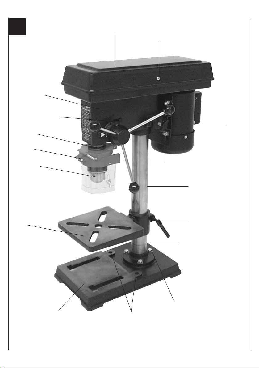
6.2. Installing the machine (Fig. 1)
Before the drill is started for the first time, it must be
solidly and fully mounted on the work area of a stable
workbench. Use both mounting holes (12) in the
base plate to do this. Ensure that the machine is
freely accessible for operation, adjustment and
maintenance.
Note: The fixing screws may only be tightened to a
point where they do not distort or deform the base
plate. Excessive tension can lead to fracture.
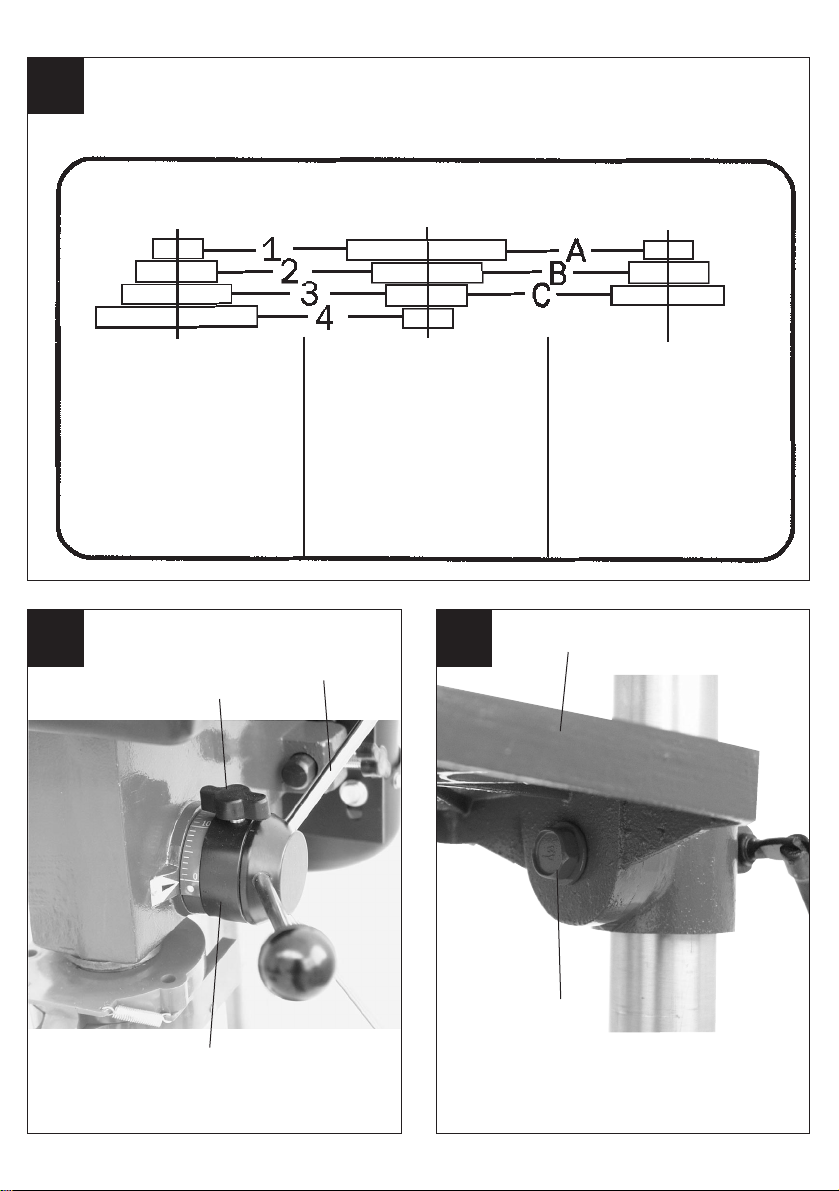
6.3. Hinged chip guard (Fig. 4)
Unscrew the three recessed head screws (21).
Push the transparent cover (23) into the groove of
the red mounting frame (24) and fasten it again with
the recessed head screws (21).
The height of the cover (23) is infinitely adjustable
and can be locked using the two thumb screws (22).
The chip guard (13) can be flipped upwards to
change drill bits; ensure, however, that the chip
guard (13) is back in its initial position before
restarting the machine.
6.4. Prior to starting
Ensure that the voltage of the mains supply complies
with the specifications on the rating plate. Connect
the machine only to a socket with the properly
installed earthing contact.
The table drill is equipped with a no-volt trip that is
designed to protect the operator from an undesired
restart following a drop in voltage. Should this occur,
the machine must be manually restarted.
7.0. Operation
Wear suitable, protective clothing (i.e.
rugged and tight-fitting) when working
with the table drill.
Always wear safety goggles!
Long hair should always be bound
back with a hair net or a cap!
7.1. General (Fig. 2)
To switch on the machine, push in the green On
button „I“ (18); the machine starts up. To switch off,
press the red Off button „O“ (19); the device shuts
down. Ensure that you do not overload the device. If
the sound of the motor drops in pitch during
operation, it is being overloaded. Do not overload the
device to the point where the motor comes to a
standstill.
The machine is designed for continuous operation
with intermittent load (S6 50 %).
The machine may be operated under a full load for a
maximum of 5 minutes, at which time the machine
needs to idle for 5 minutes. This prevents the motor
from overheating.
7.2. Tool insertion (Fig. 1)
Ensure that the mains plug is pulled out before
changing tools. Only cylindrical tools with a
maximum shaft diameter of Ø 1.5 - 16 mm may be
clamped in the scroll chuck (10). Only use a tool that
is sharp and free of defects. Do not use tools whose
shaft is damaged or which are deformed or flawed in
any other way. Only insert accessories and
attachments that are specified in the operating
instructions or have been approved by the
manufacturer.
7.3. Handling the drill chuck (Fig. 1)
Your table drill is equipped with a scroll chuck (10).
In order to insert a drill bit, flip up the chip guard (13),
insert the drill bit, then tighten down the drill chuck
using the supplied chuck key.
Pull out the chuck key. Ensure that the clamped in
tool is firmly seated.
Caution! Do not leave the chuck key in the clamp
hole.
Doing so will cause it to shoot out, which could cause
injury.
GB

9
7.4. Setting the speed (Fig. 1/5/6)
First switch the machine off, then pull out the mains
plug.
The various spindle speeds can be set by moving the
V-belt.
Proceed as follows:
Remove the screw (16) in order to open the V-
belt cover (7).
Slacken the tightening screw (15) and push the
motor (8) in the direction of the machine head.
Move the V-belt to the desired position.
Refer to the table for the recommended speeds
for different drill bit materials.
Tighten the V-belt by pushing the motor (8) back
from the machine head (6). Screw the tightening
screw (16) back down again. The tension is
properly set when the V-belt flexes in the middle
by approx. 1 cm when pressed.
Close the V-belt cover and screw down using the
screw (16).
The V-belt cover (7) must always be locked tight, as
the machine is equipped with a safety switch that
only allows the machine to be turned on when the V-
belt cover (7) is closed.
Caution! Never let the pillar drill run when the V-belt
cover is open. Always pull out the mains plug before
opening the cover. Never touch the V-belt when it is
rotating.
7.5. Drill depth stop point (Fig. 7)
The drilling spindle has a swiveling scale ring for
setting the drill depth. Only adjust the setting when
the machine is at a standstill.
-Lower the drilling spindle (11) until the tip of the drill
bit touches the workpiece.
-Slacken the clamping screw (17) and turn the scale
ring (25) forwards until it stops.
-Turn the scale ring (25) back to the desired drill
depth, then lock this setting into place using the
clamping screw (17).
7.6. Setting the angle of the drill table (Fig. 8)
Slacken the carriage bolt (26) under the drill
table (4).
Set the drill table (4) to the desired angle (which
can be read off the scale on the top side of the
drill table).
Tighten down the carriage bolt (26) in order to
lock the drill table (4) into this position.
7.7. Setting the height of the drill table (Fig. 1)
Slacken the tightening screw (5).
Set the drill table (4) to the desired height by
pressing down or lifting up and simultaneously
(gently) pushing to the left or right.
Screw the tightening screw (5) back down again.
7.8. Locking the workpiece into position (Fig. 1)
As a general rule, use a machine vice (14) or another
suitable clamping device to lock a workpiece into
position.
Never hold the workpiece in place with your
hand!
When drilling, the workpiece should be able to travel
on the drill table (4) for self-centering purposes.
Ensure that the workpiece cannot rotate. This is best
achieved by placing the workpiece/machine vice on a
sturdy block.
Caution! Sheet metal parts must be clamped to
prevent them from being torn up. Properly set the
height and angle of the drill table for each workpiece.
There must be enough distance between the upper
edge of the workpiece and the tip of the drill bit.
7.9. Drilling wood
Please note that sawdust must be properly extracted
when working with wood, as it can pose a health
hazard. Ensure that you wear a suitable dust mask
when performing work that generates dust.
7.10. Working speeds
Ensure that you drill at the proper speed. Drill speed
is dependent on the diameter of the drill bit and the
material in question.
The table below acts as a guide for selecting the
proper speed for various materials.
Note: The drill speeds specified are merely
suggested values.
GB

10
Drill bit Ø Cast iron Steel Iron Aluminium Bronze
32550 1600 2230 9500 8000
41900 1200 1680 7200 6000
51530 955 1340 5700 4800
61270 800 1100 4800 4000
71090 680 960 4100 3400
8960 600 840 3600 3000
9850 530 740 3200 2650
10 765 480 670 2860 2400
11 700 435 610 2600 2170
12 640 400 560 2400 2000
13 590 370 515 2200 1840
14 545 340 480 2000 1700
16 480 300 420 1800 1500
18 425 265 370 1600 1300
20 380 240 335 1400 1200
22 350 220 305 1300 1100
25 305 190 270 1150 950
7.11. Countersinking and center-drilling
With this table drill, you can also countersink and
center-drill. Please observe that countersinking
should be performed at the lowest speed, while a
high speed is required for center-drilling.
8.0. Care and maintenance
The table drill is to a large extent maintenance-free.
Keep the device clean.
Pull out the mains plug before doing any cleaning
and maintenance work on the machine.
Do not use any harsh, abrasive cleaning solvents.
Ensure that no liquid seeps into the device.
Regrease all bare parts when the work is finished.
The drill pillar, blank parts of the column, and the drill
table especially should be regreased at regular
intervals. Use a standard, acid-free lubricating
grease to do this.
Caution: Do not use your household refuse bin as a
receptacle for oil and grease-soaked cleaning rags or
grease and oil sludge. Dispose of these toxic
materials in an environmentally-friendly fashion.
Regularly check and clean the ventilation holes.
Store the device in a dry room. Should the device
become damaged, do not try to repair it yourself;
leave this work to the hands of a qualified electrical
technician.
9.0. Ordering replacement parts
Replacement parts can be ordered through ISC
GmbH (see the warranty declaration for the
address). The following information should be
provided when placing an order:
-Model/type of device
-Item number of device
-I.D. number of device
-Number of the required replacement part
GB

11
Expolsion Diagram BD 501 Art.-Nr.: 42.505.23 I.-Nr.: 01011
42.505.21.02
42.505.21.03
42.505.21.04
42.505.21.05
42.505.21.01
o. Abb. Keilriemensatz 2-tlg. 42.505.21.07
o. Abb. Montagebeutel incl. Griffe 42.505.21.08

12
EG Konformitätserklärung
Der Unterzeichnende erklärt im
Namen der
Firma
Achivierung / For archives: 4250520-4155050-E
BD 501
–Seriennummer auf
dem Produkt –
der
EG Maschinenrichtlinie
98/37/EG mit
Änderungen
EG Niederspannungs-
richtlinie 73/23 EWG
EG Richtlinie Elektro-
magnetische Verträglichkeit
89/336 EWG mit
Änderungen entspricht.
Landau/Isar, den
16.10.2001
Brunhölzl
Produkt-Management
Typ
Marke
daß die
Maschine/Produkt
EC Declaration of Conformity
The Undersigned declares, on
behalf of
–Serial number specified on
the product -
is in accordance with the
EC Directive regarding
machinery 98/37 EC, as
amended;
EC Directive regarding
low-voltage equipment
73/23 EEC;
EC Directive regarding
electromagnetic compatibility
89/336 EEC, as amended.
Landau/Isar, (date)
16.10.2001
Brunhölzl
Head of Product Management
Landau/Isar, (date)
16.10.2001
Brunhölzl
Direction Gestion Produits
Landau/Isar, datum
16.10.2001
Brunhölzl
Hoofd produkt management
Landau/Isar
16.10.2001
Brunhölzl
Director de gestión productos
Landau/Isar
16.10.2001
Brunhölzl
Chefe da Gestão de Produtos
Type
produced by:
that the
Machine / Product
Déclaration de Conformité CE
Le soussigné déclare, au nom
de
–no. série indiqué sur le
produit -
correspond(ent) à la
Directive CE relative aux
machines 98/37 CE avec
les modifications y
apportées;
Directive CE relative aux
basses tensions 73/23 CEE;
Directive CE relative à la
compatibilité électro-
magnétique 89/336 CEE
avec les modifications y
apportées.
– serienummer op het produkt-
conform de volgende
richtlijnen is:
EG machinerichtlijn
98/37/EG met wijzigingen
EG laagspanningsrichtlijn
73/23 EWG
EG richtlijn Elektro-
magnetische compatibiliteit
89/336 EWG met wijzigingen
Type
du fabricant
que
la machine / le produit
EC Conformiteitsverklaring
De ondertekenaar verklaart in
naam van de
firma
type
merk
dat de
machine/produkt
Declaracion CE de
Conformidad
Por la presente, el abajo
firmante declara en nombre de
la empresa
–No. de serie en el producto:
satisface las disposiciones
pertinentes siguientes:
Disposición de maquinaria
de la CE 98/37/CE con
modificaciones
Disposición de baja tensión
de la CE 73/23 CEE
Disposición de la
compatibilidad electro-
magnética de la CE 89/336
CEE con modificaciones.
tipo
marca
que el/la
máquina/producto
EC Overensstemmelses-
erklæring
Undertegnede erklærer på
vegne af firmaet
–Serienummer på produktet -
opfylder
EU-maskindirektiv
98/37/EF med ændringer
EU-lavspændingsdirektiv
73/23/EØF
EU-direktiv vedr.
elektromagnetisk støj (EMC)
89/336/EØF med ændringer.
type
mærke
at
maskine/produkt
ISC GmbH · Eschenstaße 6 · D-94405 Landau/Isar
Säulenbohrmaschine Pillar Drill Perceuse à colonne Kolomboormachine Taladradora de
columna Søjleboremaskine
DIN EN 292 Teil 1; DIN EN 292 Teil 2; DIN EN 55014-1; DIN EN 55014-2; DIN EN 61000-3-2; DIN EN 61000-3-3; DIN EN 61029-1

13
Notes:

14
Notes:

15
Notes:

16
WARRANTY CERTIFICATE
The guarantee period begins on the date of sale and
is valid for 2 years.
Responsibility is assumed for faulty construction or
material or functional defects.
Any necessary replacement parts and necessary
repair work are free of charge.
We do not assume responsibility for consequential
damage. Your statutory rights are not affected.
Your customer service partner
Einhell UK Ltd
Brook House, Brookway
North Chesire Trading Estate
Prenton, Wirral, Chesire
CH 43 3DS
Tel. 0151 6084802, Fax 0151 6086339
Technical specification subject to change
wegm. 11/01
Service UK:
Table of contents
Other Powercraft Drill manuals