3
Installation (Cont.)
Place equipment as close to the work
area as possible to minimize piping
runs.
Each pump has rubber mounts to
reduce the vibrations transmitted to
the vacuum system. A flexible hose or
flexible connector should be used for
installation between the collection
tank and the pump intake.
INLET FILTRATION (available
separately)
Inlet filtration is required to prevent
solid particles from entering the vacu-
um pump. Powerex offers both paper
and polyester inline filters to 10
micron, which assure 99% particulate
free air. Certain applications such as
the pumping of solvents, alkaline solu-
tions or corrosive vapors may require
an additional carbon filter.
WIRING
Refer to the general safety manual. All
electrical hook-ups must be performed
by a qualified electrician. Installations
must be in accordance with local and
national electrical codes. Use solderless
terminals to connect the electrical
power source.
PIPING
Refer to the general safety manual.
1. Never use any piping, which is
smaller than the pump or tank con-
nection.
2. Make sure the piping is properly
placed to reach the pump connec-
tions. Ensure that the piping is not
strained or twisted during assembly
or after final hookup.
3. Anchor piping supports separately
from the pump to reduce noise and
vibration.
4. Install flexible hose or properly
designed bends at the vacuum
pump inlet and outlet to avoid
stresses caused by vibration and/or
temperature changes.
Operation
BEFORE STARTUP
1. Make sure all safety warnings,
labels and instructions have been
read and understood before contin-
uing.
2. Remove any shipping materials,
brackets, etc.
3. Confirm electric power source and
ground have been firmly connected.
4. Be sure all vacuum and/or pressure
connections are tight.
5. Ensure all fuses, circuit breakers, etc,
are properly sized.
6. Maker sure an inlet filter is present
and properly installed.
7. Close the tank drain valve.
8. Verify the pump has the proper oil
level.
9. Visually inspect the rotation of the
vacuum pump. If the rotation is
incorrect, have a qualified electri-
cian correct the motor wiring.
STARTUP AND OPERATION
1. Follow all procedures under
“Before Startup” before attempt-
ing to operate the vacuum pumps.
2. Switch on the electrical power
source and apply power to the sys-
tem.
3. Open the tank inlet valve complete-
ly.
4. Check for excessive vibration,
unusual noise or leaks during opera-
tion.
5. Close the tank inlet valve complete-
ly.
6. Check the vacuum gage to insure
that the designated vacuum setting
is reached.
Switch the power breaker to OFF if the
vacuum pump is not going to be used
right away. If the vacuum pump is
going to be out of use for 3 months or
more, see “Long Term Shutdown”
LUBRICATION
Check lubricating oil level before each
use. Refill as necessary using only
Powerex recommended oil. See
Maintenance section, Oil Change for
listing.
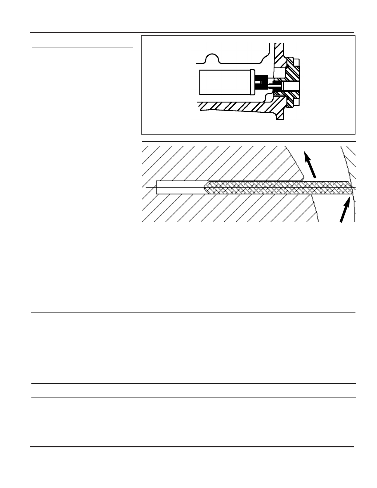
GAS BALLAST
A gas ballast device is provided on all
pumps to rid water emulsion in the
lubrication oil. The gas ballast is a quar-
ter turn ball valve located under the
metal shroud directly behind the intake
flange. To access the gas ballast valve,
turn the pump to OFF, remove the two
screws holding the small access plate in
place and remove the plate, open or
close the gas ballast valve as needed,
reinstall the plate, turn the pump to
ON.
Before using the gas ballast, allow the
pump to reach normal operating tem-
perature by running without load for
approximately 10 minutes. Open the
gas ballast valve (see procedure in pre-
ceding paragraph). Remove condensate
from the lubricating oil by operating
the vacuum pump for 30 minutes with
Rotary Vane Vacuum Pumps
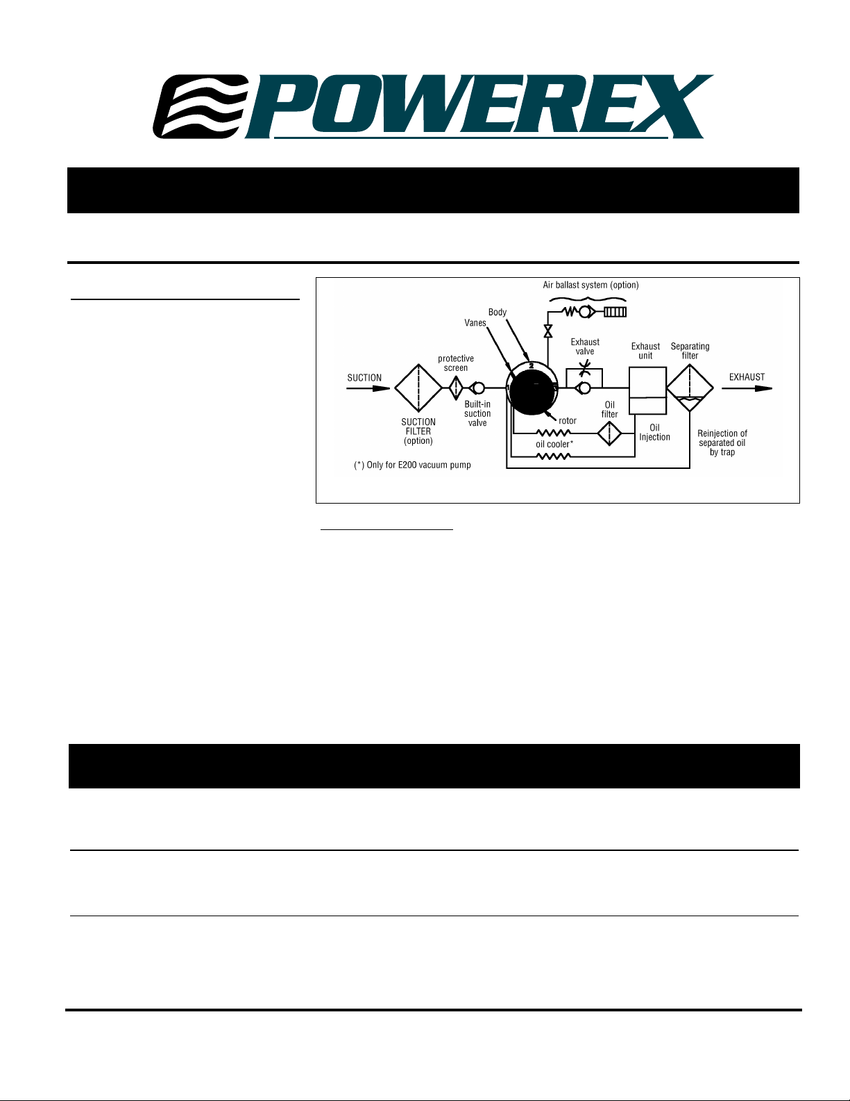
Figure 3 - Installation