Versa-Matic E4 Parts list manual

Versa-Matic
E4 Metallic Pumps
• Aluminum
• Cast Iron
• Stainless Steel
1 1/2" Elima-Matic Clamped Metallic
with Metallic Center Section
E4
VERSA-MATIC® • Warren Rupp, Inc. • A Unit of IDEX Corporation
800 North Main Street, Mansfield, OH 44902 USA • Phone: (419) 526-7296 • www.versamatic.com
© Copyright 2013 Warren Rupp, Inc. All rights reserved
-
See E4AAxxxx0
- -
REV
REVISION
CHG
DATE
THIS IS A PROPRIETARY DOCUMENT. DO NOT REPRODUCE OR DISCLOSE
WITHOUT THE EXPRESS WRITTEN PERMISSION OF WARREN RUPP INC.
DESCRIPTION
DRAWING NUMBER
WARREN RUPP INC.
REV
01
E4AAxxxx0
E4 CLAMPED
1: PUMP SPECS2: INSTAL & OP3: EXP VIEW4: WARRANTY
Original Instructions
Service & Operating Manual

e4mdlAsmC-rev1213
www.versamatic.com
IMPORTANT
Read the safety warnings and instructions in this manual
before pump installation and start-up. Failure to comply with
the recommendations stated in this manual could damage the
pump and void factory warranty.
When used for toxic or aggressive uids, the pump should
always be ushed clean prior to disassembly.
Airborne particles and loud noise hazards. Wear eye and ear
protection.
Before maintenance or repair, shut off the compressed air line,
bleed the pressure, and disconnect the air line from the pump.
Be certain that approved eye protection and protective clothing
are worn at all times. Failure to follow these recommendations
may result in serious injury or death.
When the pump is used for materials that tend to settle out
or solidify, the pump should be ushed after each use to
prevent damage. In freezing temperatures the pump should be
completely drained between uses.
Before pump operation, inspect all fasteners for loosening
caused by gasket creep. Retighten loose fasteners to prevent
leakage. Follow recommended torques stated in this manual.
CAUTION
WARNING
Nonmetallic pumps and plastic components are not UV
stabilized. Ultraviolet radiation can damage these parts and
negatively affect material properties. Do not expose to UV light
for extended periods of time.
In the event of diaphragm rupture, pumped material may enter
the air end of the pump, and be discharged into the atmosphere.
If pumping a product that is hazardous or toxic, the air exhaust
must be piped to an appropriate area for safe containment.
This pump is pressurized internally with air pressure during
operation. Make certain that all fasteners are in good condition
and are reinstalled properly during reassembly.
Take action to prevent static sparking. Fire or explosion can
result, especially when handling ammable liquids. The pump,
piping, valves, containers and other miscellaneous equipment
must be properly grounded.
Safety Information
UNIVERSAL ALL AODD

e4mdlAsmC-rev1213
www.versamatic.com
Table of Contents
SECTION 1: PUMP SPECIFICATIONS................1
•Nomenclature
•Performance
•Materials
•DimensionalDrawings
SECTION 2: INSTALLATION & OPERATION......5
•PrincipleofPumpOperation
•TypicalInstallationGuide
•Troubleshooting
SECTION 3: EXPLODED VIEW...........................8
•CompositeDrawings
•PartsList
•MaterialsCode
SECTION 4: WARRANTY & CERTIFICATES ....12
•Warranty
•ECDeclarationofConformity-Machinery
Universal*
1: PUMP SPECS2: INSTAL & OP3: EXP VIEW4: WARRANTY

e4mdlAsmC-rev1213
www.versamatic.com
1 • Model E4 Metallic Clamped
Explanation of Pump Nomenclature
*More than one option may be specied for a particular pump model.
Model Pump Size Wetted Parts Non-Wetted Parts Diaphragm Material
E Elima-Matic 61/4" AAluminum AAluminum 1 Neoprene
UUltra-Matic 83/8" CCast Iron SStainless Steel 2Nitrile(Nitrile)
VV-Series 51/2" SStainless Steel PPolypropylene 3 FKM(Fluorocarbon)
RE AirVantage 73/4" HAlloy C GGroundableAcetal 4EPDM
11" PPolypropylene ZPTFE-coatedAluminum 5PTFE
41-1/4"or1-1/2" KKynar JNickel-platedAluminum 6SantopreneXL
22" GGroundableAcetal CCast Iron 7Hytrel
33" BAluminum(screenmount) QEpoxy-CoatedAluminum 9Geolast
YFDASantoprene
Diaphragm Series Valve Ball Material Valve Seat/Valve Seat O-Ring Material Construction Design Miscellaneous Options
RRugged 1Neoprene 1 Neoprene 9Bolted BBSPTaperedThread
DDome 2 Nitrile 2Nitrile 0Clamped CPCenterPort
XThermo-Matic 3(FKM)Fluorocarbon 3(FKM)Fluorocarbon ATEXATEXCompliant
TTef-Matic(2-piece) 4EPDM 4EPDM Design Level FPFoodProcessing
BVersa-Tuff(1-piece) 5PTFE 5PTFE A SPSanitaryPump
FFUSION(one-piece 6SantopreneXL 6SantopreneXL C HPHighPressure
integratedplate) 7Hytrel 7Hytrel OEOriginalElima-Matic
8 Polyurethane 8Polyurethane FFlap Valve
9Geolast 9Geolast HDHorizontalDischarge
AAcetal AAluminumw/PTFEO-Rings 3A3-ACertied
SStainless Steel SStainlessSteelw/PTFEO-Rings ULULListed
YFDASantoprene CCarbonSteelw/PTFEO-Rings OBOilBottle
HAlloyCw/PTFEO-Rings
TPTFEEncapsulatedSiliconeO-Rings
YFDASantoprene
Model
Pump Size
Wetted Parts
Non-Wetted Parts
Diaphragm Material
Diaphragm Series
Valve Ball Material
Valve Seat Material/Valve Seat O-Ring Material
Construction Design
Design Level
Options (if applicable)
Your Serial #: (ll in from pump nameplate) _____________________________________
Model #:
__ __ __ __ __ __ __ __ __ __ __ __ __
(ll in from pump
nameplate)
Your Model #:
UNIVERSAL TO ALL VM
1: PUMP SPECS

e4mdlAsmC-rev1213
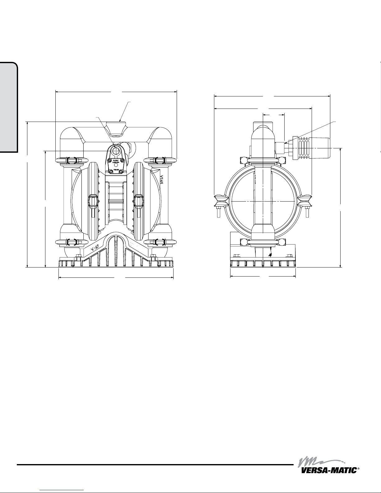
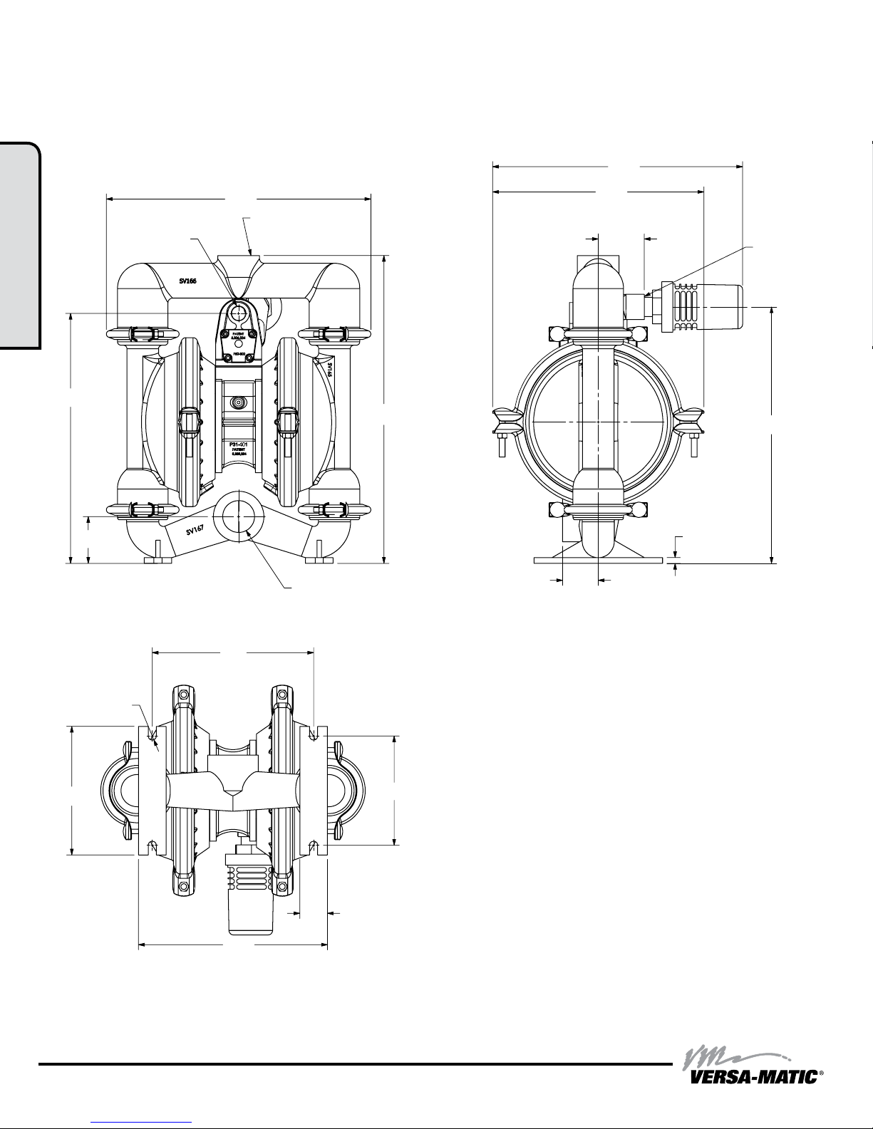
www.versamatic.com Model E4 Metallic Clamped • 2
Materials
Material Prole: Operating
Temperatures:
Max. Min.
Conductive Acetal: Tough,impactresistant,ductile.Good
abrasionresistanceandlowfrictionsurface.Generallyinert,with
goodchemicalresistanceexceptforstrongacidsandoxidizing
agents.
190°F
88°C
-20°F
-29°C
EPDM:Showsverygoodwaterandchemicalresistance.Has
poorresistancetooilsandsolvents,butisfairinketonesand
alcohols.
280°F
138°C
-40°F
-40°C
FKM:(Fluorocarbon)Showsgoodresistancetoawiderange
ofoilsandsovents;especiallyallaliphatic,aromaticand
halogenatedhydrocarbons,acids,animalandvegetableoils.
Hotwaterorhotaqueoussolutions(over70°F)willattackFKM.
350°F
177°C
-40°F
-40°C
Hytrel®:Goodonacids,bases,aminesandglycolsatroom
temperaturesonly.
220°F
104°C
-20°F
-29°C
Neoprene:Allpurpose.Resistancetovegetableoils.Generally
notaffectedbymoderatechemicals,fats,greasesandmany
oilsandsolvents.Generallyattackedbystrongoxidizingacids,
ketones,estersandnitrohydrocarbonsandchlorinatedaromatic
hydrocarbons.
200°F
93°C
-10°F
-23°C
Nitrile: Generalpurpose,oil-resistant.Showsgoodsolvent,oil,
waterandhydraulicuidresistance.Shouldnotbeusedwith
highlypolarsolventslikeacetoneandMEK,ozone,chlorinated
hydrocarbonsandnitrohydrocarbons.
190°F
88°C
-10°F
-23°C
Nylon: 6/6Highstrengthandtoughnessoverawide
temperaturerange.Moderatetogoodresistancetofuels,oils
andchemicals.
180°F
82°C
32°F
0°C
Polypropylene:Athermoplasticpolymer.Moderatetensile
andexstrength.Resistsstongacidsandalkali.Attackedby
chlorine,fumingnitricacidandotherstrongoxidizingagents.
180°F
82°C
32°F
0°C
PVDF:(PolyvinylideneFluoride)Adurableuoroplasticwith
excellentchemicalresistance.ExcellentforUVapplications.
Hightensilestrengthandimpactresistance.
250°F
121°C
0°F
-18°C
Santoprene®:Injectionmoldedthermoplasticelastomerwith
nofabriclayer.Longmechanicalexlife.Excellentabrasion
resistance.
275°F
135°C
-40°F
-40°C
UHMW PE:Athermoplasticthatishighlyresistanttoabroad
rangeofchemicals.Exhibitsoutstandingabrasionandimpact
resistance,alongwithenvironmentalstress-crackingresistance.
180°F
82°C
-35°F
-37°C
Urethane:Showsgoodresistancetoabrasives.Haspoor
resistancetomostsolventsandoils.
150°F
66°C
32°F
0°C
Virgin PTFE:(PFA/TFE)Chemicallyinert,virtuallyimpervious.
VeryfewchemicalsareknowntochemicallyreactwithPTFE;
moltenalkalimetals,turbulentliquidorgaseousuorineand
afewuoro-chemicalssuchaschlorinetriuorideoroxygen
diuoridewhichreadilyliberatefreeuorineatelevated
temperatures.
220°F
104°C
-35°F
-37°C
Maximum and Minimum Temperatures are the limits for which these materials can be operated.
Temperatures coupled with pressure affect the longevity of diaphragm pump components.
Maximum life should not be expected at the extreme limits of the temperature ranges.
Metals:
Alloy C:EqualtoASTM494CW-12M-1specicationfornickelandnickelalloy.
Stainless Steel: EqualtoorexceedingASTMspecicationA743CF-8Mforcorrosion
resistantironchromium,ironchromiumnickelandnickelbasedalloycastingsfor
generalapplicaitons.Commonlyreferredtoas316StainlessSteelinthepumpindustry.
For specic applications, always consult the Chemical Resistance Chart.
CAUTION! Operating temperature limitations are as follows:
AFTERMARKET PARTS
Pumper Parts is your single source for parts that
t Air-Operated Double Diaphragm (AODD) pumps
• Wilden®
• ARO®
• Yamada®
RIGHT PART, RIGHT NOW
Designed to perform equal to or greater
than original equipment manufacture.
Phone: (419) 526-7296
info@pum perparts.com
www.pumperparts.com
Pumper Parts and its products are not affiliated with any of the original equipment manufacturers referenced herein. All original equipment manufacturers’ names, colors, pictures, descriptions and part numbers are used for identification
purposes only. Pumper Parts® is a registered trade name of IDEX Corporation. All other trademarks, registered trademarks and product names are the property of their respective owners. Yamada®is a registered trademark of
Yamada Corporation. ARO®is a registered trade name of Ingersoll-Rand Company. Wilden® is a registered trade name of Wilden Pump and Engineering Company, a Dover Resources Company.
MODEL SPECIFIC UNIVERSAL ALL AODD
1: PUMP SPECS

e4mdlAsmC-rev1213
www.versamatic.com
3 • Model E4 Metallic Clamped
Performance
E4 1 1/4" Clamped Pump
PTFE Fitted
Flow Rate
Adjustableto .......0-64gpm(242.3lpm)
Port Size
Suction .................... 11/2"NPT
Discharge.................. 11/4"NPT
Air Inlet ......................1/2"NPT
Air Exhaust ..................3/4"NPT
Suction Lift
Dry ........................12'(3.7m)
Wet........................29'(8.8m)
Max Solid Size(Diameter)
......................3/16"(4.76mm)
Max Noise Level .............98dB(A)
Shipping Weights
Aluminum ................55lbs(25kg)
Cast Iron.................95lbs(43kg)
Stainless Steel ............92lbs(42kg)
E4 1 1/4" Clamped Pump
ELASTOMERIC AND TPE FITTED
Flow Rate
Adjustableto ........ 0-71gpm(268lpm)
Port Size
Suction .................... 11/2"NPT
Discharge.................. 11/4"NPT
Air Inlet ......................1/2"NPT
Air Exhaust ..................3/4"NPT
Suction Lift
Dry ........................19'(5.8m)
Wet........................31'(9.4m)
Max Solid Size(Diameter)
......................3/16"(4.76mm)
Max Noise Level ............101dB(A)
Shipping Weights
Aluminum ................55lbs(25kg)
Cast Iron.................95lbs(43kg)
Stainless Steel ............92lbs(42kg)
NOTE: Performance based on the following: PTFE tted pump, ooded suction, water at ambient
conditions. The use of other materials and varying hydraulic conditions may result in deviations in
excess of 5%.
NOTE: Performance based on the following: elastomeric tted pump, ooded suction, water at
ambient conditions. The use of other materials and varying hydraulic conditions may result in
deviations in excess of 5%.
Discharge Head in PSI
0
140
120
100
80
60
40
20
0
Capacity in Liters Per Minute
Capacity in U.S. Gallons Per Minute
Displacement Per Stroke, 0.25 Gal. (0.95 L)
AIR CONSUMPTION IN SCFM
AIR PRESSURE IN PSI
SCFM M3/HR
5 8.5
10 17
20 34
30 51
40 68
50 85
60 101.9
0 2010
510 20 30 40
50
60
4030 50 60 70 80
Meters Feet
00
40
80
120
160
200
240
280
320
10
20
30
40
50
60
80
90
70
0
1
2
3
4
5
6
7
8
9
10
BAR
50 100 150 200 250 300
Discharge Head in PSI
0
140
120
100
80
60
40
20
0
Capacity in Liters Per Minute
Capacity in U.S. Gallons Per Minute
Displacement Per Stroke, 0.13 Gal. (0.49 L)
AIR CONSUMPTION IN SCFM
AIR PRESSURE IN PSI
SCFM M3/HR
10 17
20 34
30 51
40 68
50 85
60 101.9
0 2010
10 20 30
40
50
60
4030 50 60 70
Meters Feet
00
40
80
120
160
200
240
280
320
10
20
30
40
50
60
80
90
70
0
1
2
3
4
5
6
7
8
9
10
BAR
50 100 150 200 250
1: PUMP SPECS

e4mdlAsmC-rev1213
www.versamatic.com Model E4 Metallic Clamped • 4
E4 Metallic Clamped - Aluminum
Dimensionsininches(metricdimensionsinbrackets)
The dimensions on this drawing are for reference only. A certied drawing can be requested if physical dimensions are needed.
Dimensional Drawings
2.55
13.54
16.98
14.36
[364.74]
[343.92]
[64.77]
[431.29]
[346.96]
[292.10]
[36.75]
[352.81]
[223.27]
[177.80]
[261.11]
[261.11]
[7.87]
[55.88]
1 1/4" NPT / BSP TAPERED
DISCHARGE PORT
1 1/2" NPT / BSP TAPERED
SUCTION PORT
1/2" NPT
AIR INLET
7.00
8.79
5.90
10.28
1.50
R
.20
11.50
13.66
2.20
.31
2.51
13.89
3/4" NPT
AIR EXHAUST
NOTES:
1. THE DIMENSIONS ON THIS DRAWING ARE FOR REFERENCE ONLY. A CERTIFIED DRAWING
CAN BE REQUESTED IF PHYSICAL DIMENSIONS ARE NEEDED.
BOTTOM VIEW
1
UPDATED TO CURRENT DESIGN
MAV
10/12/10 3309
REV
REVISION
CHG
DATE
ECN
THIS IS A PROPRIETARY DOCUMENT. DO NOT REPRODUCE OR DISCLOSE
WITHOUT THE EXPRESS WRITTEN PERMISSION OF WARREN RUPP INC.
MADE FROM
WETTED END MATERIAL:
PART NUMBER
DESCRIPTION
DRAWING NUMBER
WARREN RUPP INC.
REV
1
DO NOT SCALE
DRAWING
DIMENSIONS
ARE INCHES
SHEET
C
6
7
8
A
8 7 654321
D
B
D
C
B
A
E4AAxxxx01
E4 ALUMINUM CLAMPED PUMP
1 1of
E4AAxxxx01
ALUMINUM
SEE BOM
ALL DIAPHRAGM TYPES
ELASTOMERIC MATERIAL:
AIR END MATERIAL:
ALUMINUM
Model Specic
1: PUMP SPECS

e4mdlAsmC-rev1213
www.versamatic.com
5 • Model E4 Metallic Clamped
E4 Metallic Clamped - Base Mounted Aluminum
Dimensionsininches(metricdimensionsinbrackets)
The dimensions on this drawing are for reference only. A certied drawing can be requested if physical dimensions are needed.
Dimensional Drawings
13.70
17.14
14.28
13.50
1 1/4" NPT / BSP TAPERED
DISCHARGE PORT
1/2" NPT
AIR INLET
11.50
13.66
2.51
7.70
14.05
3/4" NPT
AIR EXHAUST
NOTES:
1. THE DIMENSIONS ON THIS DRAWING ARE FOR REFERENCE ONLY. A CERTIFIED DRAWING
CAN BE REQUESTED IF PHYSICAL DIMENSIONS ARE NEEDED.
A
UPDATED TO CURRENT DESIGN
MAV
10/12/10 3309
REV
REVISION
CHG
DATE
ECN
THIS IS A PROPRIETARY DOCUMENT. DO NOT REPRODUCE OR DISCLOSE
WITHOUT THE EXPRESS WRITTEN PERMISSION OF WARREN RUPP INC.
MADE FROM
WETTED END MATERIAL:
PART NUMBER
DESCRIPTION
DRAWING NUMBER
WARREN RUPP INC.
REV
A
DO NOT SCALE
DRAWING
DIMENSIONS
ARE INCHES
SHEET
C
6
7
8
A
8 7 654321
D
B
D
C
B
A
E4BAxxxx0
E4 SCREEN MOUNTED CLAMPED
PUMP
1 1of
E4BAxxxx0
ALUMINUM
SEE BOM
ALL DIAPHRAGM TYPES
ELASTOMERIC MATERIAL:
AIR END MATERIAL:
ALUMINUM
[346.96]
[362.71]
[435.36]
[347.98]
[342.90]
[292.10]
[36.75]
[356.87]
[195.58]
1: PUMP SPECS

e4mdlAsmC-rev1213
www.versamatic.com Model E4 Metallic Clamped • 6
E4 Metallic Clamped - Cast Iron
Dimensionsininches(metricdimensionsinbrackets)
The dimensions on this drawing are for reference only. A certied drawing can be requested if physical dimensions are needed.
Dimensional Drawings
2.63
13.74
16.88
14.36
1 1/4" NPT / BSP TAPERED
DISCHARGE PORT
1 1/2" NPT / BSP TAPERED
SUCTION PORT
1/2" NPT
AIR INLET
1.94
11.50
2.51
13.66
.50
14.09
3/4" NPT
AIR EXHAUST
R
.22
7.00
8.78
5.94
10.52
1.74
NOTES:
1. THE DIMENSIONS ON THIS DRAWING ARE FOR REFERENCE ONLY. A CERTIFIED DRAWING
CAN BE REQUESTED IF PHYSICAL DIMENSIONS ARE NEEDED.
BOTTOM VIEW
A
UPDATED TO CURRENT DESIGN
MAV
3309
REV
REVISION
CHG
DATE
ECN
THIS IS A PROPRIETARY DOCUMENT. DO NOT REPRODUCE OR DISCLOSE
WITHOUT THE EXPRESS WRITTEN PERMISSION OF WARREN RUPP INC.
MADE FROM
WETTED END MATERIAL:
PART NUMBER
DESCRIPTION
DRAWING NUMBER
WARREN RUPP INC.
REV
A
DO NOT SCALE
DRAWING
DIMENSIONS
ARE INCHES
SHEET
C
6
7
8
A
8 7 654321
D
B
D
C
B
A
E4CAxxxx0
E4 CAST IRON CLAMPED PUMP
1 1of
E4CAxxxx0
CAST IRON
SEE BOM
ALL DIAPHRAGM TYPES
ELASTOMERIC MATERIAL:
AIR END MATERIAL:
ALUMINUM
[364.74]
[349]
[66.8]
[428.75]
[49.28]
[12.70]
[357.89]
[177.80]
[223.01]
[150.88]
[44.20]
[267.21]
[346.96]
[292.10]
[36.75]
1: PUMP SPECS

e4mdlAsmC-rev1213
www.versamatic.com
7 • Model E4 Metallic Clamped
E4 Metallic Clamped - Stainless Steel
Dimensionsininches(metricdimensionsinbrackets)
The dimensions on this drawing are for reference only. A certied drawing can be requested if physical dimensions are needed.
Dimensional Drawings
2.55
13.61
16.76
14.40
1 1/4" NPT / BSP TAPERED
DISCHARGE PORT
1 1/2" NPT / BSP TAPERED
SUCTION PORT
1/2" NPT
AIR INLET
11.50
2.51
13.61
.31
1.94
13.96
3/4" NPT
AIR EXHAUST
7.00
8.78
R
.22
5.95
10.28
1.50
NOTES:
1. THE DIMENSIONS ON THIS DRAWING ARE FOR REFERENCE ONLY. A CERTIFIED DRAWING
CAN BE REQUESTED IF PHYSICAL DIMENSIONS ARE NEEDED.
BOTTOM VIEW
A
UPDATED TO CURRENT DESIGN
MAV
10/12/10 3309
REV
REVISION
CHG
DATE
ECN
THIS IS A PROPRIETARY DOCUMENT. DO NOT REPRODUCE OR DISCLOSE
WITHOUT THE EXPRESS WRITTEN PERMISSION OF WARREN RUPP INC.
MADE FROM
WETTED END MATERIAL:
PART NUMBER
DESCRIPTION
DRAWING NUMBER
WARREN RUPP INC.
REV
A
DO NOT SCALE
DRAWING
DIMENSIONS
ARE INCHES
SHEET
C
6
7
8
A
8 7 654321
D
B
D
C
B
A
E4SAxxxx0
E4 STAINLESS CLAMPED PUMP
1 1of
E4SAxxxx0
STAINLESS
SEE BOM
ALL DIAPHRAGM TYPES
ELASTOMERIC MATERIAL:
AIR END MATERIAL:
ALUMINUM
[292.10]
[365.76]
[345.69]
[345.69]
[354.58]
[177.80]
[223.01]
[151.13]
[38.10]
[261.11]
[7.87]
[49.28]
[425.70]
[64.77]
[36.75]
1: PUMP SPECS

e4mdlAsmC-rev1213
www.versamatic.com Model E4 Metallic Clamped • 8
Air-OperatedDoubleDiaphragm(AODD)pumpsarepowered
bycompressedair,nitrogenornaturalgas.
Themaindirectional(air)controlvalve①distributes
compressedairtoanairchamber,exertinguniformpressure
overtheinnersurfaceofthediaphragm
②.Atthesametime,
theexhaustingair③ frombehindtheoppositediaphragm
isdirectedthroughtheairvalveassembly(s)toanexhaust
port ④.
Asinnerchamberpressure(P1)exceedsliquidchamber
pressure (P2), the rod ⑤connecteddiaphragmsshift
together creating discharge on one side and suction on the
oppositeside.Thedischargedandprimedliquid’sdirections
arecontrolledbythecheckvalves(ballorap)⑥orientation.
Thepumpprimesasaresultofthesuctionstroke.The
suctionstrokelowersthechamberpressure(P3) increasing
thechambervolume.Thisresultsinapressuredifferential
necessaryforatmosphericpressure(P4)topushtheuid
throughthesuctionpipingandacrossthesuctionsidecheck
valveandintotheouteruidchamber⑦.
Suction(side)strokingalsoinitiatesthereciprocating
(shifting,strokingorcycling)actionofthepump.Thesuction
diaphragm’smovementismechanicallypulledthroughits
stroke.Thediaphragm’sinnerplatemakescontactwithan
actuatorplungeralignedtoshiftthepilotsignalingvalve.
Onceactuated,thepilotvalvesendsapressuresignaltothe
oppositeendofthemaindirectionalairvalve,redirectingthe
compressedairtotheoppositeinnerchamber.
Principle of Pump Operation
SAFE AIR
EXHAUST
DISPOSAL
AREA
PUMP INSTALLATION AREA
1" DIAMETER AIR
EXHAUST PIPING
1" DIAMETER AIR
EXHAUST PIPING
1" DIAMETER AIR
EXHAUST PIPING
MUFFLER
LIQUID
LEVEL
SUCTION
LINE
LIQUID
LEVEL
SUCTION
LINE
MUFFLER
MUFFLER
SUBMERGED ILLUSTRATION
Pumpcanbesubmergedifthepumpmaterialsofconstruction
arecompatiblewiththeliquidbeingpumped.Theairexhaust
mustbepipedabovetheliquidlevel.Whenthepumpedproduct
sourceisatahigherlevelthanthepump(oodedsuction
condition),pipetheexhausthigherthantheproductsourceto
prevent siphoning spills.
MODEL SPECIFIC
AirLine
DischargedFluid
DischargedStroke SuctionStroke
PrimedFluid
2: INSTAL & OP

e4mdlAsmC-rev1213
www.versamatic.com
9 • Model E4 Metallic Clamped
Installation And Start-Up
Locatethepumpasclosetotheproductbeingpumpedaspossible.Keepthesuctionlinelengthandnumberofttingstoaminimum.Donotreducethesuctionline
diameter.
Air Supply
Connectthepumpairinlettoanairsupplywithsufcientcapacityandpressuretoachievedesiredperformance.Apressureregulatingvalveshouldbeinstalledto
insureairsupplypressuredoesnotexceedrecommendedlimits.
Air Valve Lubrication
TheairdistributionsystemisdesignedtooperateWITHOUTlubrication.Thisisthestandardmodeofoperation.Iflubricationisdesired,installanairlinelubricator
settodeliveronedropofSAE10non-detergentoilforevery20SCFM(9.4liters/sec.)ofairthepumpconsumes.ConsultthePerformanceCurvetodetermineair
consumption.
Air Line Moisture
Waterinthecompressedairsupplymaycauseicingorfreezingoftheexhaustair,causingthepumptocycleerraticallyorstopoperating.Waterintheairsupplycan
bereducedbyusingapoint-of-useairdryer.
Air Inlet And Priming
Tostartthepump,slightlyopentheairshut-offvalve.Afterthepumpprimes,theairvalvecanbeopenedtoincreaseairowasdesired.Ifopeningthevalve
increasescyclingrate,butdoesnotincreasetherateofow,cavitationhasoccurred.Thevalveshouldbeclosedslightlytoobtainthemostefcientairowtopump
owratio.
Surge Suppressor
Shut-Off Valve
Pressure Gauge
Drain Port
Shut-Off
Valve
Check
Valve
Air Inlet
Discharge
Unregulated Air
Supply to Surge
Suppressor
Pipe Connection
(Style Optional)
Flexible Connector
Flexible Connector
Vacuum
Gauge
Suction
Shut-Off Valve
Drain Port Pipe Connection
(Style Optional)
Flexible
Connector
Air Dryer
Filter Regulator
P/N: 020.V107.000
Note: Pipe weight should not be supported
by pump connections.
Muffler
(Optional Piped Exhaust)
Recommended Installation Guide
Available Accessories:
1. Surge Suppressor
2. Filter/Regulator
3. Air Dryer
1
2
3
Note: Surge Suppressor and
Pipingmustbesupportedafter
theexibleconnection.
CAUTION
The air exhaust should
be piped to an area
for safe disposition
of the product being
pumped, in the event of
a diaphragm failure.
UNIVERSAL ALL AODD
2: INSTAL & OP

e4mdlAsmC-rev1213
www.versamatic.com Model E4 Metallic Clamped • 10
Recommended Installation Guide Troubleshooting Guide
Symptom: Potential Cause(s): Recommendation(s):
Pump Cycles Once Deadhead(systempressuremeetsorexceedsair
supplypressure).
Increasetheinletairpressuretothepump.Pumpisdesignedfor1:1pressureratioatzeroow.
(Doesnotapplytohighpressure2:1units).
Airvalveorintermediategasketsinstalledincorrectly. Installgasketswithholesproperlyaligned.
Bentormissingactuatorplunger. Removepilotvalveandinspectactuatorplungers.
Pump Will Not Operate
/ Cycle
Pumpisoverlubricated. Setlubricatoronlowestpossiblesettingorremove.Unitsaredesignedforlubefreeoperation.
Lackofair(linesize,PSI,CFM). Checktheairlinesizeandlength,compressorcapacity(HPvs.cfmrequired).
Checkairdistributionsystem. Disassembleandinspectmainairdistributionvalve,pilotvalveandpilotvalveactuators.
Dischargelineisblockedorcloggedmanifolds. Checkforinadvertentlycloseddischargelinevalves.Cleandischargemanifolds/piping.
Deadhead(systempressuremeetsorexceedsair
supplypressure).
Increasetheinletairpressuretothepump.Pumpisdesignedfor1:1pressureratioatzeroow.
(Doesnotapplytohighpressure2:1units).
Blockedairexhaustmufer. Removemuferscreen,cleanorde-ice,andre-install.
Pumpeduidinairexhaustmufer. Disassemblepumpchambers.Inspectfordiaphragmruptureorloosediaphragmplateassembly.
Pumpchamberisblocked. Disassembleandinspectwettedchambers.Removeorushanyobstructions.
Pump Cycles and Will
Not Prime or No Flow
Cavitation on suction side. Checksuctioncondition(movepumpclosertoproduct).
Checkvalveobstructed.Valveball(s)notseating
properlyorsticking.
Disassemblethewetendofthepumpandmanuallydislodgeobstructioninthecheckvalvepocket.
Cleanoutaroundvalveballcageandvalveseatarea.Replacevalveballorvalveseatifdamaged.
Useheaviervalveballmaterial.
Valveball(s)missing(pushedintochamberor
manifold).
Wornvalveballorvalveseat.Wornngersinvalveballcage(replacepart).CheckChemical
ResistanceGuideforcompatibility.
Valveball(s)/seat(s)damagedorattackedbyproduct. CheckChemicalResistanceGuideforcompatibility.
Checkvalveand/orseatiswornorneedsadjusting. Inspectcheckvalvesandseatsforwearandpropersetting.Replaceifnecessary.
Suctionlineisblocked. Removeorushobstruction.Checkandclearallsuctionscreensorstrainers.
Excessivesuctionlift. Forliftsexceeding20’ofliquid,llingthechamberswithliquidwillprimethepumpinmostcases.
Suctionsideairleakageorairinproduct. Visuallyinspectallsuction-sidegasketsandpipeconnections.
Pumpeduidinairexhaustmufer. Disassemblepumpchambers.Inspectfordiaphragmruptureorloosediaphragmplateassembly.
Pump Cycles Running
Sluggish/Stalling,
Flow Unsatisfactory
Overlubrication. Setlubricatoronlowestpossiblesettingorremove.Unitsaredesignedforlubefreeoperation.
Icing. Removemuferscreen,de-ice,andre-install.Installapointofuseairdrier.
Cloggedmanifolds. Cleanmanifoldstoallowproperairow
Deadhead(systempressuremeetsorexceedsair
supplypressure).
Increasetheinletairpressuretothepump.Pumpisdesignedfor1:1pressureratioatzeroow.
(Doesnotapplytohighpressure2:1units).
Cavitation on suction side. Checksuction(movepumpclosertoproduct).
Lackofair(linesize,PSI,CFM). Checktheairlinesize,length,compressorcapacity.
Excessivesuctionlift. Forliftsexceeding20’ofliquid,llingthechamberswithliquidwillprimethepumpinmostcases.
Airsupplypressureorvolumeexceedssystemhd. Decreaseinletair(press.andvol.)tothepump.Pumpiscavitatingtheuidbyfastcycling.
Undersized suction line. Meetorexceedpumpconnections.
Restrictive or undersized air line. Install a larger air line and connection.
Suctionsideairleakageorairinproduct. Visuallyinspectallsuction-sidegasketsandpipeconnections.
Suctionlineisblocked. Removeorushobstruction.Checkandclearallsuctionscreensorstrainers.
Pumpeduidinairexhaustmufer. Disassemblepumpchambers.Inspectfordiaphragmruptureorloosediaphragmplateassembly.
Checkvalveobstructed. Disassemblethewetendofthepumpandmanuallydislodgeobstructioninthecheckvalvepocket.
Checkvalveand/orseatiswornorneedsadjusting. Inspectcheckvalvesandseatsforwearandpropersetting.Replaceifnecessary.
Entrainedairorvaporlockinchamber(s). Purgechambersthroughtappedchamberventplugs.Purgingthechambersofaircanbedangerous.
Product Leaking
Through Exhaust
Diaphragmfailure,ordiaphragmplatesloose. Replacediaphragms,checkfordamageandensurediaphragmplatesaretight.
Diaphragmstretchedaroundcenterholeorboltholes. Checkforexcessiveinletpressureorairpressure.ConsultChemicalResistanceChartforcompatibility
withproducts,cleaners,temperaturelimitationsandlubrication.
Premature Diaphragm
Failure
Cavitation. Enlargepipediameteronsuctionsideofpump.
Excessiveoodedsuctionpressure. Movepumpclosertoproduct.Raisepump/placepumpontopoftanktoreduceinletpressure.
InstallBackpressuredevice(Techbulletin41r).Addaccumulationtankorpulsationdampener.
Misapplication(chemical/physicalincompatibility). ConsultChemicalResistanceChartforcompatibilitywithproducts,cleaners,temperaturelimitations
andlubrication.
Incorrectdiaphragmplatesorplatesonbackwards,
installedincorrectlyorworn.
CheckOperatingManualtocheckforcorrectpartandinstallation.Ensureouterplateshavenotbeen
worntoasharpedge.
Unbalanced Cycling Excessivesuctionlift. Forliftsexceeding20’ofliquid,llingthechamberswithliquidwillprimethepumpinmostcases.
Undersized suction line. Meetorexceedpumpconnections.
Pumpeduidinairexhaustmufer. Disassemblepumpchambers.Inspectfordiaphragmruptureorloosediaphragmplateassembly.
Suctionsideairleakageorairinproduct. Visuallyinspectallsuction-sidegasketsandpipeconnections.
Checkvalveobstructed. Disassemblethewetendofthepumpandmanuallydislodgeobstructioninthecheckvalvepocket.
Checkvalveand/orseatiswornorneedsadjusting. Inspectcheckvalvesandseatsforwearandpropersetting.Replaceifnecessary.
Entrainedairorvaporlockinchamber(s). Purgechambersthroughtappedchamberventplugs.
For additional troubleshooting tips contact After Sales Support at [email protected] or 419-524-8388
UNIVERSAL ALL AODD, EXCEPT FLAP
2: INSTAL & OP

e4mdlAsmC-rev1213
www.versamatic.com
11 • Model E4 Metallic Clamped
Composite Repair Parts Drawing
33
30
29
39 8
7
6
8
4
35
2
9
11
19
20
30
29
39
34
10
12
14
23
27
25
28
31
32
39
29
30
29
39
30
SEE PILOT
ASY DETAIL
FUSION
DIAPHRAGM
ASY
13
22
35
36
37
38
30
29
SEE NOTE 4
16
17
18
21
15
18
21
PILOT ASY DETAIL
23
27
26
25 28
24
TWO PIECE
DIAPHRAGM
ASY
23
25
METALLIC SEAT
OPTION
SCREEN MOUNTED
OPTION
General Model Specic
3: EXP VIEW

e4mdlAsmC-rev1213
www.versamatic.com Model E4 Metallic Clamped • 12
Composite Repair Parts List
Notes:
1.)Theouterdiaphragmplatematerialistomatchthewaterchambermaterial(CastIronpumpsaretouseStainlessouterdiaphragmplate)
2.)Theinnerdiaphragmplatematerialistomatchtheairchambermaterial
3.)Thismetallicseatmaterialistomatchthewaterchambermaterial.Inadditiontothisseat,(4)o-ringsareneeded.(RefNote4)
4.)(4)V170To-ringsareonlyusedwithmetallicttedseats.
5.)V=Aluminum,SV=StainlessSteel,WV=CastIron,H=Hastelloy,TC=PTFECoated,NP=NickelPlated
Air Valve Assembly
Item # Qty. Description Part Number
Aluminum Nickel Plated PTFE Coated
1- ValveBodyAssembly(includesitems2-8) P31-200 P31-200-NP P31-200-TC
2 1 Valve Body P31-201 P31-201NP P31-201TC
3 2 EndCap P50-300 P50-300NP P50-300TC
4 2 EndCapGasket P50-110
5 1 ValveBodyGasket P31-202
6 1 Valve Spool P50-104
73GlydeRingAssembly P50-104C
8 12 MountingScrews(8includedonitem1) S100A
Center Section Assembly
Item # Qty. Description Part Number
Aluminum Nickel Plated PTFE Coated
9 1 CenterBlockAssembly(Includesitem13&14) P31-400DCASY P31-401NP P31-401TC
10 2 AirChamber P31-101DC P31-101NP P31-101TC
11 2AirChamberGasket P31-109
12 8 Bolt P31-404
13 2 Bearing Sleeve P31-403
14 2 MainShaftO-Ring P24-403
15 1 PilotShaft P50-112
16 5 PilotSpacer P24-106P
17 6PilotO-Ring P24-107
18 2 PilotRing 2
19 2 Screw S1001
20 2 PilotRetainer P50-109
21 2 StopNut P24-108
22 1 Mufer VTM-6
Diaphragm Assembly / Elastomers
Item # Qty. Description
Part Number
Versa-Rugged PTFE
Two Piece Fusion
23 1 MainShaft P31-103 P31-102 P31-103
24 2 MainShaftStud N/A V221F N/A
25 2 Diaphragm(SeeBelowMaterialChart) V163xx V163TF V163F
26 2 Back-UpDiaphragm N/A V163TFB N/A
27 2InnerDiaphragmPlate(SeeNote2Below) V161C,V161CNP,V161CTC V161TIC,V161TINP,
V161TITC N/A
28 2 OuterDiaphragmPlate(SeeNote1Below) VB161, SVB161, WVB161, HVB161 V161TO,SV161TO N/A
29 4 ValveSeat(SeeBelowMaterialChart) V170xx
30 4 ValveBall(SeeBelowMaterialChart) V171xx
Wet End Assembly
Item # Qty. Description Part Number
Aluminum Cast Iron Stainless Steel Hastelloy
31 2 WaterChamber V165 WV165 SV165 HV165
32 2 LargeClampAssembly P31-110 SP31-110
33 1DischargeManifold V166 WV166 SV166 HV166
DischargeManifold(BSPOption) V166BSP WV166BSP SV166BSP N/A
34 1SuctionManifold(FootedOption) V167F WV167 SV167 HV167
SuctionManifold(BSPFootedOption) V167BSP N/A N/A N/A
35 1 SuctionManifold(ScreenMountOption) V167 N/A N/A N/A
36 1 Screen(ScreenMountOnly) V168 N/A N/A N/A
37 4Bolt(ScreenMountOnly) V302G N/A N/A N/A
38 4 Washer(ScreenMountOnly) V302GA N/A N/A N/A
39 4 SmallClampAssembly V169 SV169
Elastomer Material Specications
Material Versa-Rugged Diaphragm P/N "Ball P/N" Seat P/N
Neoprene V163N V171N V170N
Nitrile V163BN V171BN V170BN
FKM V163VT V171VT V170VT
EPDM V163ND V171ND V170ND
PTFE Seeitem#24 V171TF N/A(usemetallicseat)
Santoprene V163TPEXL V171TPEXL V170TPEXL
Hytrel V163TPEFG V171TPEFG V170TPEFG
Geolast V163G V171G V170G
Aluminum N/A N/A V170A(SeeNote3)
CarbonSteel N/A N/A V170CS(SeeNote3)
Stainless Steel N/A V171SS SV170(SeeNote3)
Alloy C N/A N/A HV170(SeeNote3)
MODEL SPECIFIC
3: EXP VIEW

e4mdlAsmC-rev1213
www.versamatic.com
13 • Model E4 Metallic Clamped
Written Warranty
5 - YEAR Limited Product Warranty
Quality System ISO9001 Certied • Environmental Management Systems ISO14001 Certied
Versa-Matic warrants to the original end-use purchaser that no product sold by
Versa-Matic that bears a Versa-Matic brand shall fail under normal use and service due to a defect in material
or workmanship within ve years from the date of shipment from Versa-Matic’s factory.
~ See complete warranty at http://www.versamatic.com/pdfs/VM%20Product%20Warranty.pdf ~
DATE: August 10, 2011
FECHA:
DATUM:
DATA:
DATO:
PÄIVÄYS:
AUTHORIZED/ APPROVED BY:
Approuve par:
Aprobado por:
Genehmigt von:
approvato da:
Goedgekeurd door:
Underskrift:
Valtuutettuna:
Bemyndiget av:
Autorizado Por:
04/19/2012 REV 07 VMQR 044FM
This product complies with the following European Community Directives:
Ce produit est conforme aux directives de la Communauté européenne suivantes:
Este producto cumple con las siguientes Directrices de la Comunidad Europea:
Dieses produkt erfüllt die folgenden Vorschriften der Europäischen Gemeinschaft:
Questo prodotto è conforme alle seguenti direttive CEE:
Dir produkt voldoet aan de volgende EG-richtlijnen:
Denna produkt överensstämmer med följande EU direktiv:
Versa-Matic, Inc., erklærer herved som fabrikant, at ovennævnte produkt er i overensstemmelse med bestemmelserne i Direkktive:
Tämä tuote täyttää seuraavien EC Direktiivien vaatimukstet:
Dette produkt oppfyller kravene til følgende EC Direktiver:
Este produto está de acordo com as seguintes Directivas comunitárias:
MANUFACTURED BY:
FABRIQUE PAR:
FABRICADA POR:
HERGESTELLT VON:
FABBRICATO DA:
VERVAARDIGD DOOR:
TILLVERKAD AV:
FABRIKANT:
VALMISTAJA:
PRODUSENT:
FABRICANTE:
DECLARATION DE CONFORMITE • DECLARACION DE CONFORMIDAD • ERKLÄRUNG BEZÜGLICH EINHALTUNG DER VORSCHRIFTEN
DICHIARAZIONE DI CONFORMITÀ • CONFORMITEITSVERKLARING •DEKLARATION OM ÖVERENSSTÄMMELSE
EF-OVERENSSTEMMELSESERKLÆRING • VAATIMUSTENMUKAISUUSVAKUUTUS • SAMSVARSERKLÄRING
DECLARAÇAO DE CONFORMIDADE
VERSA-MATIC®
Warren Rupp, Inc.
A Unit of IDEX Corporation
800 North Main Street
P.O. Box 1568
Mansfield, OH 44901-1568 USA
Tel: 419-526-7296
Fax: 419-526-7289
This product has used the following harmonized standards to verify conformance: EN809:1998+
A1:2009
Ce materiel est fabriqué selon les normes harmonisées suivantes, afin d’ en garantir la conformité:
Este producto cumple con las siquientes directrices de la comunidad europa:
Dieses produkt ist nach folgenden harmonisierten standards gefertigtworden, die übereinstimmung wird bestätigt:
Questo prodotto ha utilizzato i seguenti standards per verificare la conformita´:
De volgende geharmoniseerde normen werden gehanteerd om de conformiteit van dit produkt te garanderen:
För denna produkt har följande harmoniserande standarder använts för att bekräfta överensstämmelse:
Harmoniserede standarder, der er benyttet:
Tässä tuotteessa on sovellettu seuraavia yhdenmukaistettuja standardeja:
Dette produkt er produsert i overenstemmelse med fløgende harmoniserte standarder:
Este produto utilizou os seguintes padrões harmonizados para varificar conformidade:
PUMP MODEL SERIES: E SERIES, V SERIES, VT SERIES, VSMA3, SPA15,
RE SERIES AND U2 SERIES
Dave Roseberry
Engineering Manager
DECLARATION OF CONFORMITY
2006/42/EC
on Machinery, according
to Annex VIII
MODEL SPECIFIC
4: WARRANTY
Table of contents
Other Versa-Matic Water Pump manuals

Versa-Matic
Versa-Matic E8 Non-Metallic Bolted Parts list manual

Versa-Matic
Versa-Matic Porta-Matic SPA153 Parts list manual

Versa-Matic
Versa-Matic ROCKSTAR VMB Parts list manual

Versa-Matic
Versa-Matic VMB20F Parts list manual

Versa-Matic
Versa-Matic E4 Series User manual

Versa-Matic
Versa-Matic E1 Parts list manual

Versa-Matic
Versa-Matic E6 Parts list manual

Versa-Matic
Versa-Matic E3 Parts list manual

Versa-Matic
Versa-Matic E5 User manual

Versa-Matic
Versa-Matic E3 User manual