Powermate LiftGate LV-TL Series User manual

T20-090.01ForSerialNumbers38000andhigher
PN 019900 TL Rev. D
PN 389780 Rev. D
Eng. 04/18/19
T20-190.03ForSerialNumbers38000andhigher

Section 1 - General
Warning Page………………………………………….
PowerMate LiftGate Description……………………..
Delivery and W arranty Registration………………….
Section 2 - Safety
Hazard Graphical Symbols…………………………...
LiftGate Mandatory Decals… … … …… … …… … … ...
Mandatory Safety Decal Placement…………………
Safety Precautions…………………………………….
Section 3 - Instructions
LiftGate Operating Instruction………………………..
Loading Instruction for 360 Lb. LiftGate…………….
Installation D imensional Requirem ents… … … … … ..
Installation Kit………………………………………….
Additional Item s and Tools… … … … … … … … … … …
Determining Installation Location…………………….
Base Hole Locations…………………………………..
Installing the LiftGate Unit… … … … … … … … … … … .
Running the Wires……………………………………..
Section 4 - LV-Series PowerMate Components
Replacement Component Drawing………………….
Replacement Component List………………………..
Screw Assembly LV-Series…………………………..
Brake Assembly Kit……………………………………
Bearing Override Kit…………………………………..
Section 5 - Maintenance
M aintaining the PowerM ate LiftG ate… … … … … … ..
Screw Assembly Removal……………….…………...
Brake Assembly Replacement……………………….
Override Bearing Assembly Procedure……………..
Drive Screw Removal/Installation Instruction………
Screw Assembly Installation………………………….
Drive Screw Rem oval/Installation Drawing..............
Motor Removal and Installation Instruction…………
Ballnut Removal and Replacement………………….
Retract Stroke Adjustment……………………..……..
Roller Replacement……………………………………
Back Bar Assembly……………………………………
LV-Series Wiring Diagram……………………………
Actuator Manual Retraction…………………………..
Section 6 - Specifications
PowerM ate LiftGate Specifications… … … …… … … .
Solidstate Controller Specifications………………….
Section 7 - Accessory Installations
Back Bar Installation…………………………………...
Section 8 - Accessories
LG /V-3 LiftG ate Features… … … … … … … … … … … .
LG /V-6 LiftG ate Features… … … … … … … … … … … .
Warranty………………………………………………..
Declaration of Conformity…………………………….
Daily Maintenance Schedule…………………………
1.01
1.02
1.02
2.01
2.02
2.04
2.05
3.01
3.02
3.03
3.04
3.05
3.06
3.07
3.08
3.09
4.01
4.02
4.03
4.04
4.05
5.01
5.02
5.03
5.03
5.03
5.04
5.05
5.07
5.08
5.09
5.10
5.11
5.12
5.13
6.01
6.02
7.01
8.01
8.02
8.03
8.04
8.05
PowerMate
®
LiftGate™ Installation & Operation Manual
TABLE OF CONTENTS
PN 019020 TL Rev. B
Eng. 04/ 19/ 19
i

W
ARNING
ATTENTION!
The photographs, diagrams and illustrations in his
manual are of the LG-6 Right-hand unit installation in
a box truck. Use this manual as a guideline when
installing Left-hand units and/or other LG/LV-Series
units in alternative locations in other vehicle types.
Failure to obey the Instructions and Safety
rules in this manual could result in death or
serious injury.
Read the Operating Manual completely.
Only competent, trained operators may use
this equipment.
Training is essential to understanding all the
features and capabilities of your PowerMate,
and ensure good safe work practices.
Training courses are available through
L P INTERNATIONAL INC., please call
1-800-697-6283
PowerMate
®
LiftGate™ Installation & Operation Manual
PN 019100 TL Rev.A
Eng. 04/ 04/ 17
1.01

Manufactured By:
L P INTERNATIONAL INC.
P.O. Box 696, 151 Savannah Oaks Drive
Brantford, Ontario, Canada N3T 5P9
TEL: (519) 759-3292 FAX: (519) 759-3298
1-800-697-6283
PowerMate
®
LiftGate™
DELIVERY AND WARRANTY REGISTRATION
In choosing to buy a PowerMate
®
, you will find that it will help your business in more
ways than you can imagine. Not only is it a revenue generator, PowerMate®is also a
labour saver and a great promotional tool to help you expand your business in the
commercial and industrial markets.
The PowerMate®LiftGate™ provides a safe and easy way for moving and delivering
heavy and awkward loads in and out of your vehicle at the push of a button.
We at L P INTERNATIONAL INC. look forward to continuing our mission to help you
realize your full profit potential of having a PowerMate®LiftGate™ in your Profit
Center.
For more information on the complete PowerMate®product line, please call toll free
1-800-697-6283.
Upon receipt of your LiftGate™ unit, examine the unit to determine if it has been
damaged in transit. Examine the unit for mishandling, paying particular attention to
the control box and switches, the limit switch assembly and the exposed wire
looms.
If required, make note of any deficiencies on the Delivery Acceptance Form.
Registering your unit for the Warranty can be done online at www.powermate.info.
Click on Service, fill in the required fields under Warranty and click Send Now.
When ordering parts, or requesting information or service on the unit, please refer
to the model and serial number. The model number can be found on the data
decal on the top of the control box. The serial number can be found stamped to
the top corner of the aluminum outer frame.
PowerMate
®
LiftGate™ Installation & Operation Manual
WARNING The use of this equipment with any options other than
those specified in this manual may create a hazard.
PN 019910 TL Rev.A
Eng. 04/ 04/ 17
1.02

The PowerMate
®
products use graphical symbols, safety colours, and signal words
throughout the Operators Manual and on the units themselves. Operators using the
PowerMate®must familiarize themselves with these symbols.
NOTICE: The signal word to address practices not
related to personal injury.
CAUTION: Indicates a potentially hazardous situation
which, if not avoided, may result in minor
or moderate injury.
WARNING: Indicates a potentially hazardous situation
which, if not avoided, could result in death
or serious injury.
DANGER: Indicates an imminently hazardous situation
which, if not avoided, will result in death or
serious injury.
Safety Alert Symbol: This symbol indicates a potential personal
injury hazard. Safety information following
this symbol must be followed to avoid
possible injury or death.
HAZARD GRAPHICAL SYMBOLS
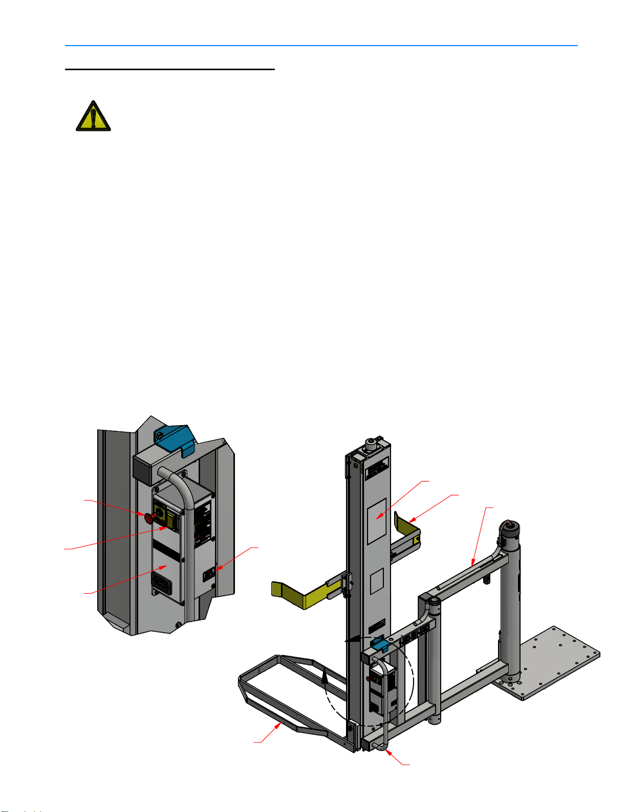
SAFETY LABEL MAINTENANCE
Safety of the operator and surrounding environment must be considered at all times.
To that end, safety labelling on the PowerMate®must be maintained to provide legible
safety information. Clean the labels with soap and water. Do not use solvent-based
cleaners because they may damage the labels. Replace damaged or missing labels.
Replacement labels may be purchased from L P International Inc. Customer Service
Phone number 1-800-697-Mate.
PowerMate
®
LiftGate™ Installation & Operation Manual
2.01 PN 019090 TL Rev.A
Eng. 04/ 04/ 17

PowerMate
®
LiftGate™ Installation & Operation Manual
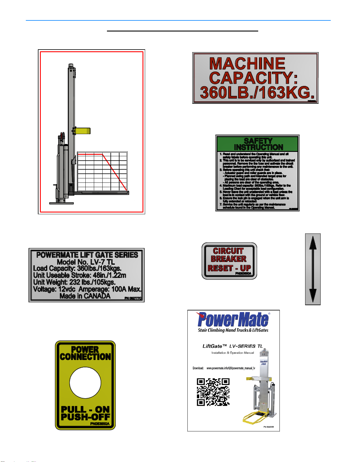
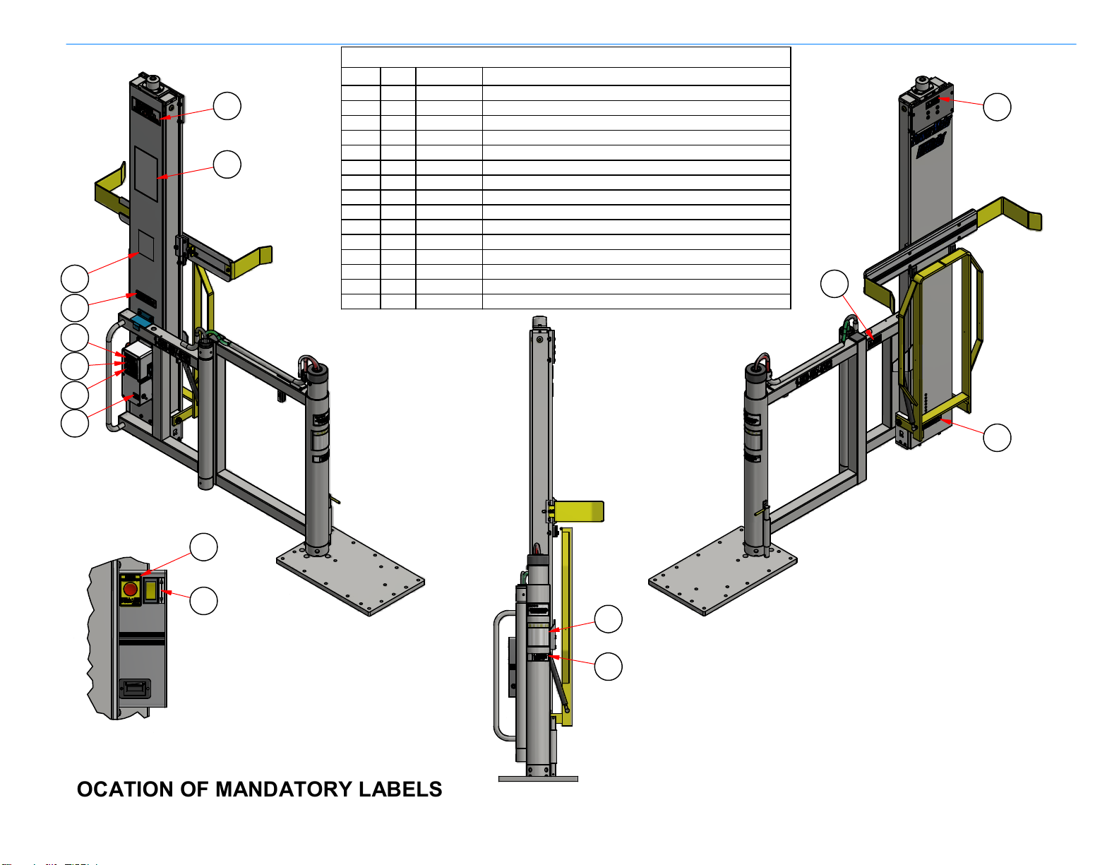
DANGERS, WARNINGS, AND CAUTIONS
The following decals are mandatory. Refer to the Location of Mandatory Labels Drawing
for placement. Replacement decals are available from LP International Inc.
PN 057020A
PN 082650B
PN 057050A
PN 057080A
PN 057010A
PN 019040 TL Rev.B
Sheet 1 of 2
Eng. 04 / 19/ 19
2.02
PN 057030A
PowerMate
®
LiftGate™ Installation & Operation Manual
A
DDITIONAL MANDATORY DECALS
The following decals are mandatory. Refer to the Location of Mandatory Labels Drawing
for placement. Replacement decals are available from LP International Inc.
360(163)Max.
TOEPLATEFACE
LOAD CENTER OF GRAVITY
4" 8" 12" 24"
18"
LOAD
lbs.(kgs.)
POWERMATE
LIFT GATE 360Lb.(163Kg.) SERIES
16"
PN 082777C
PN 084060A
PN 083890B
PN 084020B
PN 083880A
PN 019040 TL Rev.B
Sheet 2 of 2
Eng.04/ 19/ 19
2.03
170(77)
210(95)
250(113)
290(132)
340(154)
PN 082710C
PN 083870A
PN 083850A
PowerMate
®
LiftGate™ Installation & Operation Manual
NOTE: Indicated Decals are intended to create awareness in
operators, owners, and maintenance personnel, of the
potential safety hazards and operational limits. Insure
that these decals are in place. Replacements are
available from L P International Inc.
LOCATION OF MANDATORY LABELS
FOR 360Lb. LV-7 LIFTGATE UNITS
PARTS LIST
DESCRIPTION
PART No.
QTY
ITEM
DANGER DECAL - CRUSH HAZARD FOOT
057020A11
DECAL - MOVING PARTS082650B12
WARNING DECAL - MOVING PARTS Small
057080A13
WARNING DECAL - KEEP OFF057050A14
DECAL - WARNING AUTHORIZED PERSONNEL
057010A1
5
DECAL - LOAD CAPACITY 360Lb.084060A16
DECAL-SAFETY INSTRUCTION LG-SERIES 360Lb.
083890B1
7
DECAL - LOADING CHART LV-7 TL082710C18
DECAL - LV-7 TL SPECIFICATIONS082777C
19
DECAL - MANUAL WEB REFERENCE LV-7 TL084020B110
DECAL - UP / DOWN ARROW
083870A111
DECAL - CIRCUIT BREAKER RESET083880A112
DECAL - POWER CONNECTION LV-7
083850A113
DANGER DECAL - ELECTRICAL SHOCK057030A114
DECAL - FAULT ALERTS
057160A115
PN 019030 TL Rev.B
Eng. 04/ 19/ 19
2.04
SWITCH SIDE OF
CONTROL BOX
8
10
9
3
14
12
62
1
7
5
13
11
15
4

PowerMate
®
LiftGate™ Installation & Operation Manual
WARNING:Read and understand all instructions. Follow the safety rules listed below
as well as the other basic safety precautions. Failure to do so may result
in serious injury.
WORK ARE
A
CHECK YOUR WORK AREA. Inspect your work are for obstacles such as holes,
debris or rough spots. Look for areas not able to support the load, such as access
or drain covers or soft ground. Watch out for liquid spills or slippery surfaces. Be
on the alert for anything that might cause you to lose your balance, control or
concentration. Insure that the vehicle is level. The LiftGate™ unit should not be
activated if the vehicle is on any inclination.
PLAN YOUR WORK. Arrange your work to avoid unnecessary steps or effort.
Position your vehicle for proper clearance from roadside curbs and obstacles.
Insure that the Load Chart is considered when engaging the load to be
transferred. Do not overload the PowerMate.
KEEP YOUR WORK AREA CLEAR. All visitors should be kept away from the
work area.
PERSONAL SAFET
Y
STAY ALERT. Always focus your attention in the direction of travel. Always maintain
proper footing and balance. Constantly check for clearance above, below and on all
sides. When loading onto or off of a vehicle, be prepared for movement in the
vehicle suspension system.
USE COMMON SENSE. Do not operate equipment when you are tired or injured.
Keep both hands positioned on unit at all times. Never play games. Do not ride on
the unit. Do not attempt to use the equipment as a jack.
MAINTAIN THE EQUIPMENT REGULARLY
DO NOT operate equipment that is known to be damaged or malfunctioning. Never
remove or override any mechanical or electrical safety devices. Poorly maintained
equipment jeopardizes the safety of the operator and all other personnel. Remember
safety is your responsibility. Complete a daily inspection procedure. Have the
equipment thoroughly checked by a competent service person at least once a year.
SECURE FOR TRANSPORT
When the equipment is not in use, ensure the LiftGate™ and the load are fully secure
before moving the vehicle.
PN 019110 TL Rev.A
Eng. 04/ 04/ 17
SAFETY PRECAUTIONS
2.05
WARNING! The vehicle must be parked on a level surface prior to operating the
LiftGate Unit. Safety shoes must be worn! Read the instructions completely
before operating the unit. DO NOT exceed Max. Capacity Limit.
PowerMate
®
LiftGate™ Installation & Operation Manual
OPERATING INSTRUCTIONS
1. Refer to the Loading Chart, in this Manual or on the face of the LiftGate Inner Frame, to
determine if the load to be lifted will fit in the load capacity envelope of the PowerMate unit.
2. Pull the Power Disconnect Switch to the “ON” position.
3. The Rocker Switch controls the up/down operation of the unit. Depressing the top of the switch
will raise the Toeplate Loop and depressing the bottom of the switch will lower the Toeplate
Loop. Raise the Toeplate Loop off the surface and dis-engage the Lock Pin, to allow
positioning of the unit. Maneuver the Toeplate Loop to the load and lower the Toeplate Loop to
the surface. Place load on the Toeplate Loop and ensure the load is engaged with the unit
Back Bar if the load is high enough.
4. Raise the load to the desired height. The actuator mechanism will stop automatically when the
top stroke limit is reached, at which point the rocker switch should be released.
5. Swing the load to required position using the unit Handle. Use the Lock Pin whenever
possible.
6. Lower the load down to the desired surface (vehicle floor or the ground). The down stroke will
end automatically when the Toeplate Loop makes contact with any surface. Remove the load.
7. When the operation is complete, park the unit folded in the vehicle. Engage the Lock Pin,
lower the Toeplate Loop to the floor until the actuator stops (automatic), and depress the
Power Disconnect Switch to the Off position.
DETAIL A A
PN 019330 TL Rev.B
Eng. 04/ 19/ 19
3.01
Handle
Back Bar
Loading Chart
Power
Disconnect
Switch
Rocker
Switch
Control Box
Toeplate Loop
Circuit Breaker
Toggle Switch
Main Swing Arm

PowerMate
®
LiftGate™ Installation & Operation Manual
INSTRUCTIONS:
The above Loading Chart indicates the maximum load that can be lifted by the LiftGate Unit
at a specific center of gravity. The center of gravity is measured as the distance from face of
the Toeplate to the balance point of the load. Estimate the weight of the load and the center
of gravity distance out from the face of the Toeplate. Locate on the chart the Weight/Center
of Gravity location for the load. The load must not exceed the weight limit for the given center
of gravity distance.
POWERMATE 360Lb. LIFTGATE LOAD CHART
NOTE: This is a copy of the Load Chart on the Inner Frame of the Lift Gate Unit.
360(163)Max.
TOEPLATEFACE
LOAD CENTER OF GRAVITY
4" 8" 12" 24"
18"
LOAD
lbs.(kgs.)
POWERMATE
LIFT GATE 360Lb.(163Kg.) SERIES
16"
PN 019310 TL Rev.B
Eng. 04 / 19/ 19
3.02
340(154)
290(132)
250(113)
210(95)
170(77)
TOEPLATE

PowerMate
®
LiftGate™ Installation & Operation Manual
INSTALLATION DIMENSIONAL REQUIREMENTS
LiftGate
Model No. Minimum Door Opening Maximum Height of
Base above ground.
LV-7 71.50" (1816mm) 39" (990mm)
PN 019400 TL Rev.B
Eng. 04/ 19/ 19
3.03
Toeplate extended.
Toeplate folded.
Minimum
Door
Opening
26 5/8"
20 1/2"
39 3/4"
Maximum
height of base
above ground.
PowerMate
®
LiftGate™ Installation & Operation Manual
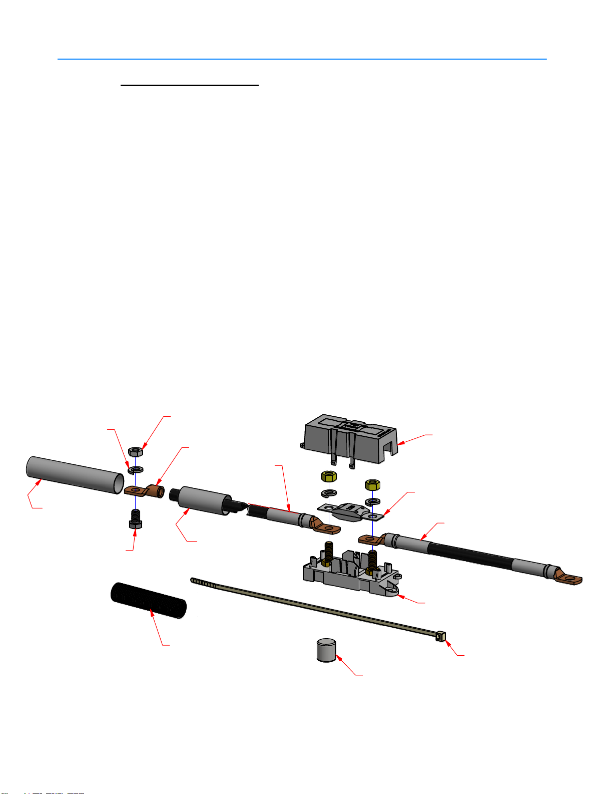
INSTALLATION KIT
Your installation package should include the following:
1 PowerMate® LiftGate™ Unit complete with pre-drilled Base
1 Wiring Kit which includes the following:
1 Bolt-Down Fuse Holder
1 125A
1 Fuse Holder Cover
1 Cable Splice 6Ga.
1 25' of 5/8” Split Loom
20 11"Cable Ties
1 Heat Shrink Tube 3/4” x 2”
1 Heat Shrink Tube 3/4” x 4”
4 Lock Pin Plug
1 5/16-18NC x 1/2" Bolt
1 5/16-18NC Jam Nut
1 5/16” Lock Washer
1 Fuse Block Wire Assembly
1 Hook-up Wire Assembly
PN 019410 TL Rev.B
Eng. 04/ 19/ 19
3.04
Fuse Block Wire Assembly
125A Fuse
11"Cable Tie
Lock Pin Lug
Fuse Holder Cover
Hook-up Wire
Assembly LV
Heat Shrink
Tube 3/4"x 4"
Jam Nut 5/16-18
Bolt 5/16-18NC x 1/2" Heat Shrink
Tube 3/4"x 2"
2Ga. Copper Lug
Bolt-Down Fuse Holder
Split Loom 5/8"x 25Ft.
5/16"Lock Washer

PowerMate
®
LiftGate™ Installation & Operation Manual
ADDITIONAL ITEMS & TOOLS
NOTE:
Some adjustments to the Unit's Base Plate may need to be made in order to fit
the Unit around some areas of the vehicle (wheel wells, etc.) A cutting torch
may be required to reshape the Unit's Base Plate.
The installer will need to provide following tools and materials to proceed with installation:
- Drill with 13/32" Metal Drill Bit.
- 1" to 2" Metal Hole Saw.
- Wire Cutter.
- Crimping Pliers.
- 9/16 Wrench.
- 9/16 Socket & Ratchet.
- 3/8"-16NC Bolts of suitable length*.
- Wire Loom for wire protection.
- Steel Flat Bar, Angle, and/or C-Channel for vehicle floor reinforcement.
- Screw or Bolt/Nut combination to secure Ground Lug Terminal to vehicle frame.
* The length of the Bolts are dependant on thickness of vehicle floor and vehicle floo
r
reinforcement. Therefore, bolt length can only be determined at time of installment.
PN 019420 TL Rev.A
Eng. 04/ 04/ 17
3.05

INSTALLING YOUR PowerMate® LiftGate
STEP 1: Determining the location of unit installation.
A. Although you will want the Unit placed close to the rear doors and side of the
vehicle, you will need to ensure the proper allowances:
I. Make sure there is enough room to close the rear
doors.
II. The Base Pole must be far enough away from the
vehicle wall to clear the doorway when swinging
out, and allow you to easily access the Locking
Pin.
Below Example:
LG-6 LiftGate
placement in rear location of a truck box.
PowerMate
®
LiftGate™ Installation & Operation Manual
PN 019430 TL Rev.A
Eng. 04/ 04/ 17
3.06

PowerMate
®
LiftGate™ Installation & Operation Manual
B. Position the Unit in the vehicle and mark the outline of the Base Plate on the floor.
Using a transfer punch and the Unit Base as a template, mark the bolt hole
locations on the vehicle floor. Move the Unit out of the way. Using the dimensions
provided in the sketch below, mark the center point of the large hole.
CAUTION!!
Before any holes are made in the vehicle floor, ensure the following: The large
hole for the wiring must not damage the vehicle's supporting structure. Check the
underbody of the vehicle to ensure the hole locations will not interfere with brake
or fuel lines, fuel tank, wiring, or any other critical areas of the vehicle. If the area is
not free of obstacles, re-position the Unit and repeat this step.
POWERMATE LIFTGATE
BASE HOLE LOCATIONS
Make 1" to 2" hole at
this location for wiring to
pass through floor of
vehicle.
12.000
15.500
20.000
6.000
.750 3.000
2.875
.750
4.625
.438
Drill 13/32"holes through vehicle
floor as required. Be cautious of
what may be on the bottom side.
Utilize as many hole positions as
possible. Additional holes may be
drilled through the Base Plate if
necessary.
This area is removed on the
LG-3 Lefthand Base Plates.
This area is removed on the
LG-3 Righthand Base Plates.
.750
3.500
PN 019440 TL Rev.A
Eng. 04/ 04/ 17
3.07
INSTALLING YOUR PowerMate® LiftGate
STEP 2: Installing the Unit
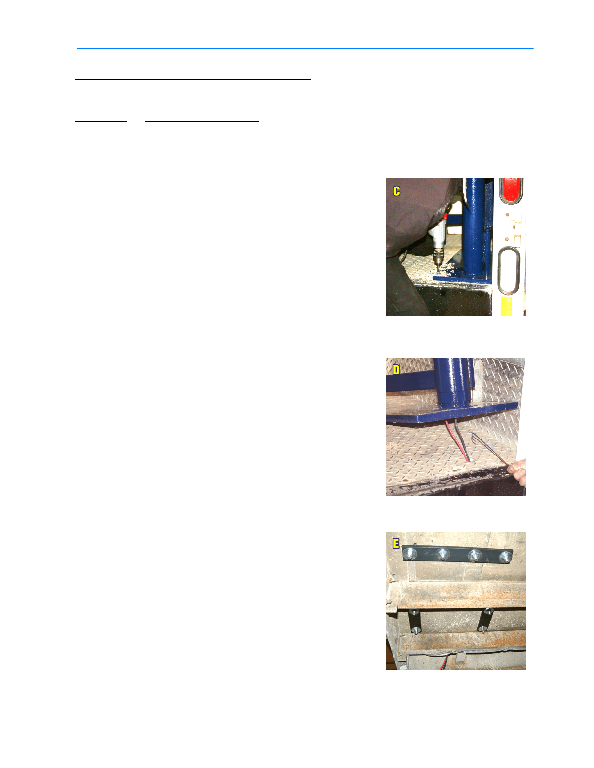
C. Proceed to drill the marked large hole and 13/32"
holes into the floor of the vehicle. Use as many
bolt holes in the Base as possible.
NOTE:
In some instances it may not be possible to utilize
all the bolt holes due to the structuring underneath
the
vehicle floor. In these cases, additional holes can
be added.
CAUTION!!
Be sure to not drill into anything vital under
the floor.
D. Reposition the PowerMate® LiftGate
Unit over
the marked outline, lining up the large hole with the
Main Post. Tip the Unit back to fish out the two
wires hidden in the Main Post. Direct the wires
through the large hole in the floor.
CAUTION!!
Care must be taken not to damage the
wires.
E. The installer is required to reinforce the Unit under
the floor, below the Base Plate, with Steel Flatbar,
Angle, and/or C-Channel.
NOTE:
Reinforcing steel will need to be measured, cut to
size and drilled with 13/32" holes.
PowerMate
®
LiftGate™ Installation & Operation Manual
PN 019450 TL Rev.A
Eng. 04/ 04/ 17
3.08

INSTALLING YOUR PowerMate® LiftGate
F. Secure the Base to the floor and the reinforcing steel with
3/8"-16NC Bolts, Washers and Lock Nuts.
STEP 3: Running the wires
CAUTION!!
The best and easiest way to route the wire from the Unit to the
vehicle battery is to follow the path from the rear lights. If this is not
feasible you must avoid the following:
I. Any heat sources. EG. Exhaust system.
II. Any pinch points. EG. Suspension system.
III. Any areas that may cause chaffing to occur on the wiring.
G. The BLACK wire that exits the Base Assembly and is fed
through the floor must be fastened to a suitable Ground on
the vehicle frame.
H. Slip a piece of Heat Shrink Tube over the RED wire.
I. Connect the RED wire to the 6Ga. wire using the 6Ga.
Cable Splice and shrink the tubing over the connection.
J. Provide a protective wire loom for the entire length of wire
installation including up through the floor into the Base
Assembly.
PowerMate
®
LiftGate™ Installation & Operation Manual
PN 019460 TL Rev.A
Eng. 04/ 04/ 17
3.09

INSTALLING YOUR PowerMate® LiftGate
K. Route the 6Ga. wire to the vehicle battery, securing
wire to vehicle frame as required.
L. Slip a piece of Heat Shrink Tube over the 6Ga. wire.
Join wire to Fuse Holder with 6Ga. Cable Splice and
shrink tubing over the connection.
M. Attach Cable Lug to POSITIVE post of the battery.
N. Insert the 125A Fuse into the Fuse Holder and attach the
Fuse Holder Cover.
O. Test the Unit.
PowerMate
®
LiftGate™ Installation & Operation Manual
PN 019470 TL Rev.A
Eng. 04/ 04/ 17
3.10

PowerMate
®
LiftGate™ Installation & Operation Manual
DETAIL A
A
POWERMATE LV-SERIES LIFTGATE
REPLACEMENT COMPONENT LIST
4.01 PN 019500 TL Rev.B
Sheet 1 of 2
Eng. 04/ 19/ 19
1.4.1.2
1.4.7
1.4.4
1.4.5
1.4.14
1.4.6
1.4.1.5
1.4.8
1.4.11
1.4.12
1.4.1.3
1.4.1.4
1.4.8
1.1.2.21.7
1.1.2.21.9
1.1.2.21.3
1.1.2.21.19
1.1.2.21.16
1.1.2.21.17
1.1.2.21.18
1.1.2.21.4
1.1.2.21.2
1.1.2.21.1
1.1.2.16
1.4.26
1.1.2.20
1.1.2.25
1.1.2.14
1.1.1
1.1.3.1
1.1.3.2
1.1.3.3
1.1.3.7
1.1.3.4
1.1.9
1.3.1
1.3.2
1.3.7
1.3.6
1.3.8
1.3.3
1.3.5
1.1.3.14
1.1.3.10
1.1.3.8.2
1.1.3.8.3
1.1.3.8.4
1.1.3.5
1.1.3.22
1.1.2.13
1.1.2.6
1.1.1
1.1.2.3
1.1.2.1
1.1.2.2
1.1.2.4
1.1.2.5
1.1.2.7
1.1.2.12
1.1.2.17
1.1.10
1.1.8
1.1.3.7
1.1.3.21
1.1.3.17
1.1.3.12
1.1.3.12
1.1.6
1.1.3.20
1.1.2.26
1.1.2.23
1.1.2.24
1.1.2.18
1.1.2.5
1.1.3.9
1.1.11
1.1.2.8
1.2
1.2
1.3.9
1.4.2
1.4.9
1.4.10
1.4.13
1.1.3.27
1.1.3.26
1.1.3.25
1.1.3.24 1.1.3.19
1.1.3.23
This manual suits for next models
1
Table of contents
Other Powermate Lifting System manuals


Popular Lifting System manuals by other brands


PFlow Industries
PFlow Industries F Series Service & Maintenance and Owner’s Manual

Lehner Lifttechnik
Lehner Lifttechnik LIFTboy user manual

Snap-On
Snap-On EELR 343A Installation and operation manual

Ravaglioli
Ravaglioli RAV1140 Translation of the original instructions

Ingersoll-Rand
Ingersoll-Rand 700C Parts, operation and maintenance manual

Vancare
Vancare VANDER-LIFT II B450 operating manual