WIRTH OKTOPUS GLASS-Jack GL-CC 1200 User manual

O p e r a t i n g I n s t r u c t i o n s
Vacuum based lifting device
for glass and façade elements
OKTOPUS® GL SS-Jack
GL-CC 1200
Serial no.: A 810 930
Technical Documentation
BA 000 257
02/2017
This technical documentation corres onds to the status as of the issue date.
WIRTH GMBH
INSTALLATION SYSTEMS DIVISION
Brehnaer Straße 1
D-06188 Landsberg
Tele hone +49 (0) 34 602 / 70 88 - 0
Fax +49 (0) 34 602 / 70 88 - 111
www.wirth-gmbh.com
Original o erating manual
Note ro rietary notice as er ISO 16016

O e r a t i n g I n s t r u c t i o n s
OKTOPUS
®
GL SS-Jack
GL-CC 1200
Technical Documentation
BA 000 257
Page 2 of 28
Page
Table of Contents 2
1 General Information on the OKTOPUS
®
4
1.1 Manufacturer’s information 4
1.2 Service worksho 4
1.3 Sco e of a lication 4
2 Proper use of the OKTOPUS
®
5
2.1 Functional rinci le and safety conce t of the OKTOPUS
®
system 5
2.2 Safety instructions 6
2.3 Symbols and markings 7
2.4 Structure and use of the OKTOPUS
®
9
2.4.1 Arrangement of suction ads 11
2.5 O erating conditions and restrictions 11
2.6 Trans ort and storage 12
2.6.1 Trans ort by air lane 13
3 Instructions for using the OKTOPUS
®
14
3.1 Electrical ower su ly 14
3.1.1 Changing the battery ack 15
3.2 Vacuum su ly 15
3.3 Radio remote control 16
3.4 Cou ling the OKTOPUS
®
to the crane boom 18
3.5 Startu 19
3.6 Handling of glass and façade elements 19
3.7 Changing the suction frame 20
3.8 Assembly of the extension arms 22
3.9 Adjusting the suction frame to curved glass and façade anes 23
4 Service and maintenance 24
4.1 General remarks 24
4.2 Mechanical system 24
4.3 Vacuum system 25
4.3.1 Cleaning the suction ads 25
4.4 Electrical and electronic com onents 26
5 Handling incidents 28
6 Disposal and recycling 28
nnex 1: Brief instructions OKTOPUS
®
GLASS-Jack GL-CC 1200
nnex 2: Functional dimensions
nnex 3: EC Declaration of Conformity
nnex 4: Ins ection Tag according to Directive 2006/42/EG
nnex 5: Electrical Circuit Diagram

O e r a t i n g I n s t r u c t i o n s
OKTOPUS
®
GL SS-Jack
GL-CC 1200
Technical Documentation
BA 000 257
Page 3 of 28
Page
Table of figures
3
Fig. 1: OKTOPUS
®
GLASS-Jack GL-CC 1200 with suction frame for flat glass anes 9
Fig. 2: OKTOPUS
®
GLASS-Jack GL-CC 1200 with suction frame for flat glass anes incl.
extensions 10
Fig. 3: OKTOPUS
®
GLASS-Jack GL-CC 1200 with suction frame for curved glass anes 10
Fig. 4: Load lifting attachment OKTOPUS
®
GLASS-Jack GL-CC 1200 10
Fig. 5: Arrangement of suction ads 11
Fig. 6: Charge indicator 14
Fig. 7: Battery ack 15
Fig. 8: Vacuum gauge 16
Fig. 9: Transmitter radio remote control 17
Fig. 10: Cou ling the OKTOPUS
®
to the head of the crane boom 18
Fig. 11: Handling glass and façade elements 20
Fig. 12: Changing the suction frame 21
Fig. 13: Assembly of the extension arms 22
Fig. 14: Adjusting the suction frame to curved glass und façade elements 23
Fig. 15: Dust filter and suction ad 25
Fig. 16: Battery charger (sam le) 26
Fig. 17: Warning devices 28

O e r a t i n g I n s t r u c t i o n s
OKTOPUS
®
GL SS-Jack
GL-CC 1200
Technical Documentation
BA 000 257
Page 4 of 28
1 General Information on the OKTOPUS
®
1.1 Manufacturer’s information
Manufacturer’s name and registered office:
WIRTH GMBH
Installation Systems Division
Brehnaer Straße 1
D-06188 Landsberg
Device characteristics:
Product descri tion: OKTOPUS
®
GLASS-Jack GL-CC
Ty e: OKTOPUS
®
GLASS-Jack GL-CC 1200
Serial number: (see ty e late)
Year of manufacture: (see ty e late)
Weight: a rox. 210 kg
(with suction frame for flat glass anes, 8 suction ads, s. fig. 1)
a rox. 240 kg
(with suction frame for flat glass anes, 12 suction ads, s. fig. 2)
a rox. 285 kg
(with suction frame for curved glass anes, 20 suction ads, s. fig. 3)
Working Load Limit: max. 800 kg (8 suction ads
∅
400 mm)
max. 1200 kg (12 suction ads
∅
400 mm)
max. 1000 kg (20 suction ads
∅
280 mm)
see also section 2.3 Symbols and markings
CE mark: according to EC-Declaration of Conformity Annex 3
Ins ection tag according to Annex 4 attached to the device.
1.2 Service workshop
WIRTH GMBH Tele hone: +49 (0) 34 602 / 70 88 - 0
Brehnaer Str. 1 Fax no.: +49 (0) 34 602 / 70 88 - 111
1.3 Scope of application
The o erating instructions on hand re resent the state-of-the art and the safety measures
defined by the Euro ean Machinery Directive valid at the editing date of the manual.
Diverging or amending national regulations may not be considered eventually.
The user is exclusively res onsible to observe such regulations.

O e r a t i n g I n s t r u c t i o n s
OKTOPUS
®
GL SS-Jack
GL-CC 1200
Technical Documentation
BA 000 257
Page 5 of 28
2 Proper use of the OKTOPUS
®
2.1 Functional principle and safety concept of the OKTOPUS
®
system
Devices of the OKTOPUS
®
system
are “load lifting attachments” o erating according to
the rinci le “vacuum lifter”. They are mounted to a hoist or o erate as a stand-alone unit
and are used for handling and ositioning large-sized construction elements.
The basic functional rinci les of the OKTOPUS
®
system are:
⇒ controlled suction and release of large-sized construction elements having sufficient in-
herent stability using one or more suction ad(s) of the OKTOPUS
®
,
⇒ trans ort and ositioning of the sucked elements by mani ulating the OKTOPUS
®
,
⇒ vernier ositioning of the elements attached to the OKTOPUS
®
by controlling the OK-
TOPUS
®
axes (if available).
For various fields of a lication we offer different designs and ty es of the OKTOPUS
®
.
These differ de ending on the used hoist, the loads to be lifted, the required ositioning
movements and the used controls.
For further information lease contact us or visit our website at www.wirth-gmbh.com.
S ecific safety requirements, which have been taken into account during construction, exe-
cution, technical documentation and in drawing u the o erating instructions, result from the
function of the OKTOPUS
®
being a “load lifting attachment”.
Therefore, strict adherence to the instructions and information for ro er and safe use given
in the o erating manual is a rerequisite for the manufacturer’s warranty during the sti ulated
warranty eriod.
Combining the OKTOPUS
®
with a hoist is the res onsibility of the OKTOPUS
®
user. The user
himself is res onsible for ro er im lementation of the relevant guidelines and instructions.
The instructions given in this o erating manual by the OKTOPUS
®
manufacturer are consid-
ered to be additional su ort.
Prior to initial startu of the machine the suitability of the combination OKTOPUS
®
/forklift or
crane in o erating conditions has to be checked by skilled ersonnel.
Furthermore, the OKTOPUS
®
has to undergo regular ins ections by an ex ert (see oint
4.1). An ex ert is a erson that due to his technical training and ex erience has sufficient
knowledge in the area of load lifting attachments and is familiar with relevant occu ational
and safety instructions, regulations and generally recognized codes of ractice which ena-
bles him to assess o erational safety of load lifting attachments.
The initial ins ection of the combination hoist/OKTOPUS
®
as well as the successful erfor-
mance of the annual ins ection of the OKTOPUS
®
by an ex ert has to be documented.
The OKTOPUS
®
manufacturer offers ex ert ins ections as a service and documents the in-
s ections on the OKTOPUS
®
by lacing the ins ection tag on the ins ection card according
to Annex 4 with the indication of the next test date.

O e r a t i n g I n s t r u c t i o n s
OKTOPUS
®
GL SS-Jack
GL-CC 1200
Technical Documentation
BA 000 257
Page 6 of 28
2.2 Safety instructions
(1) When selecting a crane, consider the influence of the dead-weight load and load ca-
acity of the OKTOPUS
®
GL SS-Jack GL-CC 1200, the wind and acceleration loads,
the intended and unintended load eccentricities on the Working Load Limit and/or the
stability of the crane as well as resulting reductions of the carrying ca acity diagrams of
the crane.
(2) Never use a damaged, not fully functional or not com lete OKTOPUS
®
!
(3) Prior to initial startu have an expert check and document the combination crane/
OKTOPUS
®
!
(4) Only o erate the crane with an operating license!
(5) Only o erate OKTOPUS
®
and minicrane if you are familiar with the control and dis-
play elements as well as the operating manuals. You have to know how the func-
tions affect the entire installation!
(6) Prior to using OKTOPUS
®
and crane check the function of the control and display
elements as well as the warning devices!
(7) Ensure that the crane o erator is able to overview the assembly and installation site!
(8) Agree on hand signals with the rigger or installer for the necessary crane movements!
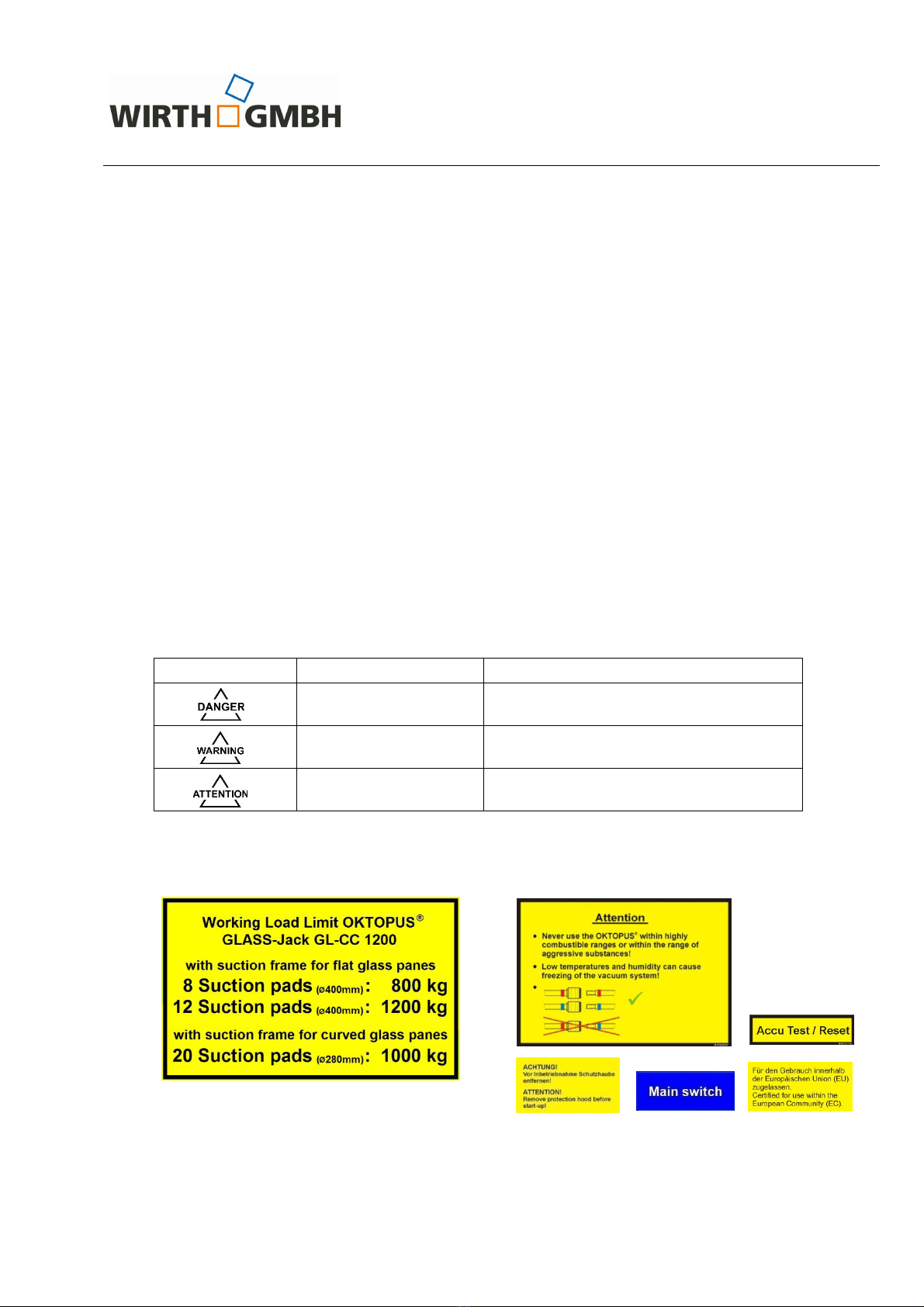
(9) It is absolutely necessary to observe the maximum Working Load Limit of the OK-
TOPUS
®
GL SS-Jack GL-CC 1200 sti ulated in section 2.3 Symbols and markings!
These s ecifications only a ly to a working height corres onding 400 m above sea
level!
(10) If the suction ads are covered by protecting cowls, these have to be removed be-
fore startu !
(11) Only work at wind s eeds less than 30 km/h, otherwise you risk uncontrollable swing-
ing of the load!
(12) Check the suction rubbers daily for damages; if necessary re lace the suction rub-
bers by new ones.
(13) Clean the suction areas of the glass anes. Do not place the suction ads on pro-
tective film, releasing agents or similar, but remove it at least at the contact areas of
the suction ads.
(14) Never stand or walk under the suspended load!
(15) Make sure that nobody climbs the OKTOPUS
®
GLASS-Jack GL-CC 1200 or the sus-
ended load and tries to ride along.
(16) Stop working instantly if the alarm buzzer sounds and/or the red warning light is
illuminated! In this case the system is severely damaged and there is the risk that the
sucked load might dro . Carefully lower the OKTOPUS
®
together with the sucked load
with the hel of the crane until the load is securely laced. The cause of the alarm has
to be found and removed. In case of unrecoverable errors all o erations with the OK-
TOPUS
®
have to be discontinued immediately. The OKTOPUS
®
has to be secured
against further use.
(17) In case of incidents and maintenance work turn off the OKTOPUS
®
. Therefore, turn
the main switch to osition OFF!
(18) Never em loy the OKTOPUS
®
in explosive areas or in the area of aggressive me-
dia!
(19) Take into consideration that low temperatures and high humidity may cause freez-
ing of the vacuum system!
(20) Never attempt to lift damaged glass or façade elements!
(21) Do not lift the load higher than necessary!

O e r a t i n g I n s t r u c t i o n s
OKTOPUS
®
GL SS-Jack
GL-CC 1200
Technical Documentation
BA 000 257
Page 7 of 28
(22) Never leave the lifted load unsu ervised!
(23) Do not suck wet elements, because
a. Working Load Limit is decreased considerably and
b. the vacuum system or the control system of the OKTOPUS
®
could be damaged!
(24) After use, rotect the suction ads of the OKTOPUS
®
against damage by using rotec-
tion cowls!
(25) lways wear suitable rotective clothing, helmets, gloves and safety shoes!
(26) Never lift more than one glass or façade element at a time!
(27) Com ly with the sti ulated maintenance information:
• daily visual and functional inspection (battery’s charge level, vacuum gauges,
suction ads, warning light, signal light, alarm buzzer, control anel)!
• de ending on the o erating conditions, but at least annually, ins ection by an ex-
ert!
(28) Never modify the OKTOPUS
®
in a way that safety is im aired. Otherwise the manu-
facturer’s warranty will be void!
(29) Do not remove information signs, safety signs and ins ection tags and lates from the
OKTOPUS
®
. Otherwise the manufacturer’s warranty will be void!
2.3 Symbols and markings
Signal word Meaning Consequences of non-com liance
Warns of imminent
threat of danger
Death or serious injury or substantial
material damage as consequence.
Warns of otential
threat of danger
Death or serious injury or substantial
material damages are ossible.
Warns of ossibly
dangerous situation
Light injury or material damages are
ossible.
Next to the ty e late the following safety-related signs and ictogra hs are attached to the
OKTOPUS
®
:
(Working Load Limit OKTOPUS
®
)
(General information / Warning signs)

O e r a t i n g I n s t r u c t i o n s
OKTOPUS
®
GL SS-Jack
GL-CC 1200
Technical Documentation
BA 000 257
Page 8 of 28
(Before o erating, r
ead and com ly
with o erating manual as well as
safety instruction!)
(Beware of sus ended
load)
(Ins ection card)

O e r a t i n g I n s t r u c t i o n s
OKTOPUS
®
GL SS-Jack
GL-CC 1200
Technical Documentation
BA 000 257
Page 9 of 28
2.4 Structure and use of the OKTOPUS
®
The OKTOPUS
®
GLASS-Jack GL-CC 1200 is a vacuum-based load lifting attachment for
large-sized glass and façade elements with sufficient inherent stability and an at least artial-
ly smooth and airtight surface. It is designed to be used as an attachment for mini cranes and
is cou led directly to the boom. De ending on the used suction frame it is ossible to handle
flat glass, curved glass (concave/convex with bending radius ≥ 2 m) or window elements.
The OKTOPUS
®
GLASS-Jack GL-CC 1200 can be o erated inside as well as outdoors.
The functional main assemblies of the OKTOPUS
®
are (s. fig. 1 to 3):
− die vacuum unit (2), that contains all com onents for generating and maintaining the vac-
uum,
− the ada ter crane boom (12) for attaching the vacuum unit to the boom,
− the vacuum gauges (15) for indicating the existing negative ressure,
− die cylinders (4, 13) for tilting and swiveling the load,
− the red warning light (16) and the alarm buzzer (17), that indicate a hazardous situation,
as well as the green signal light (21), that defines the working range,
− the main switch (20) for turning the device on/off and the transmitter of the radio remote
control (s. Abb. 9) for o erating the OKTOPUS
®
.
Fig. 1: OKTOPUS
®
GLASS-Jack GL-CC 1200 with suction frame for flat glass anes
1 Cover battery casing 12 Ada ter crane boom (exam le)
2 Vacuum unit 13 Cylinder “Swivel”
3 Electric control box 14 Drive “Rotate”
4 Cylinder “Tilt” 15 Vacuum gauge
5 Suction ad (
Ø
400 mm) 16 Warning light red
6 Suction frame for flat glass anes 17 Alarm buzzer
7 Ring gear 18 Charge indicator
8 Rotate, tilt, swivel joint 19 Button “Accu Test/Reset”
9 Antenna 20 Main switch
10 Receiver 21 Signal light green
11 Cover vacuum unit
1
3
4
5
17
18
19
20
21
9
10
11
12
1
3
1
4
1
5
6
1
6
8
7
2

O e r a t i n g I n s t r u c t i o n s
OKTOPUS
®
GL SS-Jack
GL-CC 1200
Technical Documentation
BA 000 257
Page 10 of 28
Fig. 2: OKTOPUS
®
GLASS-Jack GL-CC 1200 with suction frame for flat glass anes
incl. extensions
Fig. 3: OKTOPUS
®
GLASS-Jack GL-CC 1200 with suction frame for curved glass anes
The load lifting attachment OKTOPUS
®
GLASS-Jack GL-CC 1200 is designed as an attach-
ment and is mounted to a crane according to fig. 4.
Fig. 4: Load lifting attachment OKTOPUS
®
GLASS-Jack GL-CC 1200
22
23
22 Extension arm with suction ad
Ø
400 mm
Crane boom
Glass element
Suction ad
Vacuum unit
23 Hand wheel
24 Suction ad (
Ø
280 mm)
25 Suction frame for curved glass anes
25
24

O e r a t i n g I n s t r u c t i o n s
OKTOPUS
®
GL SS-Jack
GL-CC 1200
Technical Documentation
BA 000 257
Page 11 of 28
1500 mm
2410 mm
2200 mm
2.4.1 rrangement of suction pads
Fig. 5: Arrangement of suction ads
Please contact the Wirth service team, if an arrangement of suction ads differing from figure
5 is required.
lways distribute the suction pads evenly on both vacuum circles! Non-
compliance with these instructions could, in case of a breakdown of a vac-
uum circuit, lead to the load suddenly dropping due to an uneven load dis-
tribution.
2.5 Operating conditions and restrictions
The suction areas of the glass elements to be handled with the OKTOPUS
®
GLASS-Jack
GL-CC 1200:
•
have to be airtight,
• have to have an even, dry, oil-free and clean surface and
• must not be covered with rotective film!
1100 mm
Suction frame for flat glass anes,
without extensions, 8 suction ads
(WLL max. 800 kg)
Suction frame for flat glass anes,
with
extensions, 12 suction ads
(WLL max. 1200 kg)
1530 mm
Vacuum circuit 2 (blue) Vacuum circuit 1 (red)
1000 mm
Suction frame for curved glass anes,
20 suction ads
(WLL max. 1000 kg)

O e r a t i n g I n s t r u c t i o n s
OKTOPUS
®
GL SS-Jack
GL-CC 1200
Technical Documentation
BA 000 257
Page 12 of 28
The OKTOPUS
®
®
is delivered with suction ads for even glass and façade elements.
Generally, no statements can be made regarding the length and the width of the elements to
be installed with the OKTOPUS
®
,
®
, as this de ends – u on observing the safe work load cri-
teria – almost exclusively on the inherent rigidity and the correlating deformation behavior of
the construction elements.
Avoid suction of oil, water, va ors or aggressive gases. Ambient tem erature has to be at
least 0 °C and must not exceed 40 °C (a lies only to 1013 mbar and sea level). At low
tem eratures the ca acity of the used batteries is decreased. The airborne sound emitted by
the OKTOPUS
®
GLASS-Jack GL-CC 1200 amounts to < 70 dB(A), vibrations are at < 2,5
m/s
2
, so that no s ecial rotective measures are required.
O erating restrictions result from the limited Working Load Limit of the OKTOPUS
®
GLASS-
Jack GL-CC 1200 (s. section 2.3 Symbols and markings), as well as the erformance data,
the o erating conditions of the used crane and the building site conditions. Furthermore, you
have to regard the fact that the handled elements have to have sufficient inherent stability
and are suitable to be installed with a vacuum lifting attachment (if necessary consult with the
manufacturer of the elements).
Due to the broad variety of elements with many different surface coatings offered on the
market we cannot assume liability in case of ossible material incom atibilities between suc-
tion rubber and surface coating.
The maximum Working Load Limit sti ulated on the OKTOPUS
®
only a lies to the use of
the original suction ads and a working height of maximum 400 m above sea level. Em loy-
ing the OKTOPUS
®
in heights above 400 m leads to a decreased Working Load Limit of the
OKTOPUS
®
, on the one hand, on the other hand the OKTOPUS
®
control system needs to be
adjusted. If you want to em loy the OKTOPUS
®
in heights above 400 m, lease contact the
Wirth Service Team beforehand..
Employing the OKTOPUS
®
at heights above 400 m leads to a decreased
Working Load Limit! The Working Load Limits stipulated on the OKTOPUS
®
and in this operating manual do not apply in this case!
Never carry out unauthorized adjustments at the control system of the OK-
TOPUS
®
as it may lead to serious malfunctions of the device! It means dan-
ger to life and limb! Consult with the OKTOPUS
®
manufacturer if it is nec-
essary to adjust the control system of the OKTOPUS
®
, e.g. for height ad-
justment.
2.6 Transport and storage
The OKTOPUS
®
may be moved only by a suitable hoisting device/means of trans ort of a -
ro riate Working Load Limit.
For transport purposes put the OKTOPUS
®
out of operation! Turn the main
switch to position OFF!
Protect the rubber lip of the suction pads with protective cowls from dirt
and damage!

O e r a t i n g I n s t r u c t i o n s
OKTOPUS
®
GL SS-Jack
GL-CC 1200
Technical Documentation
BA 000 257
Page 13 of 28
In order to avoid damage due to deep discharge of the batteries during
storage, the OKTOPUS
®
has to be charged at least every two weeks.
2.6.1 Transport by airplane
The transmitter of the radio remote control is equi ed with a rechargeable lithium ion bat-
tery. Due to a licable international aviation safety regulations, this kind of battery may not
remain in the transmitter during a flight.
Remove the battery from the transmitter, if the transmitter is transported by
airplane!

O e r a t i n g I n s t r u c t i o n s
OKTOPUS
®
GL SS-Jack
GL-CC 1200
Technical Documentation
BA 000 257
Page 14 of 28
3 Instructions for using the OKTOPUS
®
3.1 Electrical power supply
Electrical ower is su lied by a battery ack 24 V / 24 Ah (2 cs. 12 V batteries in series
connection). In order to increase o erating time with the OKTOPUS
®
, it is delivered with two
battery acks. While one battery ack is built in the OKTOPUS
®
and su lies it with energy,
the second battery ack can be charged (see also section 4.4).
The charge level of the built-in battery ack is monitored and secured by a charge indicator.
It is indicated by light-emitting diodes (LED) with the signal colors yellow and red (fig. 6). A
chain of seven yellow LEDs indicates the residual charge of the battery when reaching cer-
tain charge levels. With rogressing discharge the LEDs will turn off one after another.
In order to monitor the charge level you can read the following information on the charge in-
dicator:
⇒ At a level of a rox. 70% discharge the LED on the very left starts flashing (advance
warning).
⇒ At a level of a rox. 80% discharge the last yellow LED turns off and the red LED lights
u . The alarm turns on. The alarm can only be deactivated by sto ing the work and
turning off the device. The battery has to be charged, the charge indicator has ossibly
to be reset (activated).
The charge indicator is arranged to the device according to fig. 1.
Fig. 6: Charge indicator
The button “Accu Test/Reset” (see fig. 1) that is located close to the charge indicator allows
checking the function of the charge indicator, determining the current charge level of the bat-
tery and resetting the charge indicator. If the button Accu Test/Reset is ressed ermanently
when the device is turned off, the following rogram runs automatically:
1. all LEDs are illuminated for a rox. 2 sec., if the charge indicator works ro erly,
2. after a rox. 2 sec. the LEDs indicate the current charge level of the battery,
3. after a rox. 5 sec. the charge indicator is reset, rovided that it is locked (red LED illu-
minates) or not all 7 yellow LEDs are illuminated des ite the battery is fully charged. If
the charge indicator is not reset, i.e. it does not indicate a full charge after a rox. 5 sec.
(red LED turned off, 7 yellow LED turned on) the battery voltage was not sufficient. Ei-
ther the battery system or the charging unit is defective.
If the red LED lights up instantly stop or discontinue working. Immediately
evacuate the hazard zone and lower the load, as the suctioned element
could suddenly disengage. Never stand or walk under the OKTOPUS
®
or
the suctioned element!
1 red LED 7 yellow LED

O e r a t i n g I n s t r u c t i o n s
OKTOPUS
®
GL SS-Jack
GL-CC 1200
Technical Documentation
BA 000 257
Page 15 of 28
3.1.1 Changing the battery pack
In order to change the battery ack, erform the following ste s one after another:
⇒ Unlock and then o en the cover of the battery casing.
⇒ Pull the battery ack out of the battery casing using the handle.
⇒ Put the battery ack on an even surface, as shown in fig. 7.
⇒ Push the charged battery ack, the socket of the battery charger facing u wards, into
the battery casing as far as ossible. The electrical contact is established automatically
to the electric system of the OKTOPUS
®
.
⇒ Close the cover of the battery casing and lock it.
Make sure that the cover of the battery casing is correctly locked before
you start working with the OKTOPUS
®
GL SS-Jack GL-CC 1200!
Never place the battery pack on its side as this may lead to damages of the
battery charger socket
Fig. 7: Battery ack
3.2 Vacuum supply
The vacuum su ly is effected by a battery o erated vacuum um . Starting at the vacuum
um the OKTOPUS
®
GLASS-Jack GL-CC 1200 is designed redundant, i.e. all following
com onents such as non-return valve, vacuum reservoir, ressure controller, vacuum gauge
and suction ads exist twice (2 Vacuum circuits).
The 2 vacuum circuits OKTOPUS
®
GLASS-Jack GL-CC 1200 are marked by different colors,
one color er vacuum circuit (blue and red). Make sure that only vacuum hoses and cou-
lings of the same color are interconnected.
The OKTOPUS
®
GLASS-Jack GL-CC 1200 mounted to the crane is ready for use, when a
sufficient vacuum level is reached in both vacuum tanks. The current vacuum level is con-
stantly indicated on the vacuum gauges (fig. 8).
Locking battery casing
Cover battery casing
Battery ack
Battery charger socket
Handle battery ack

O e r a t i n g I n s t r u c t i o n s
OKTOPUS
®
GL SS-Jack
GL-CC 1200
Technical Documentation
BA 000 257
Page 16 of 28
The green scale range is the
permissible working range from -0.65 bar to -0.9 bar.
Fig. 8: Vacuum gauge
During o eration the vacuum is monitored by two ressure controllers. If the vacuum is in the
working range in both vacuum circuits, the green signal light is illuminated. The OKTOPUS
®
is ready for use.
If the vacuum decreases im ermissibly in one or both vacuum circuits or the ressure rises
above -0.65 bar (red scale range), a warning is triggered automatically:
⇒ alarm buzzer sounds,
⇒ red warning light is illuminated.
Only interconnect vacuum hoses and couplings of the same color! Non-
compliance with these instructions could, in case of a breakdown of a vac-
uum circuit, lead to the load suddenly dropping due to uneven load distri-
bution.
If the alarm is activated, stop working instantly and evacuate the hazard
zone, as the sucked element could disengage suddenly. Never stand or
walk under the OKTOPUS
®
or the suctioned element!
The alarm remains active until the vacuum pressure is restored within its
permitted limits.
3.3 Radio remote control
The OKTOPUS
®
GLASS-Jack GL-CC 1200 is o erated with a radio remote control. The
transmitter of the radio remote control is shown in fig. 9.
Radio remote controls are subject to national standards. For this reason,
check if it is permitted to employ the radio unit at the operation site prior to
turning it on. In case of doubt contact the OKTOPUS
®
manufacturer.
Red range
The OKTOPUS
®
must not be o erated in
this range.
Green range
The OKTOPUS
®
may only be o erated in
this range.

O e r a t i n g I n s t r u c t i o n s
OKTOPUS
®
GL SS-Jack
GL-CC 1200
Technical Documentation
BA 000 257
Page 17 of 28
Fig. 9: Transmitter radio remote control
Starting the transmitter
1. Pull the sto button (13) out.
⇒ The light-emitting diode (A) is illuminated green or red (green = Battery ca acity is
good, red = Battery of the transmitter has to be charged).
2. Push both start buttons (11 and 12) at the same time.
⇒ The built-in buzzer bee s.
3. Release start buttons (11 and 12).
⇒ The buzzer sto s bee ing. The light-emitting diode (A) flashes green or red (green =
Battery ca acity is good, red = Battery of the transmitter has to be charged).
4. If the radio communication has been established, the light-emitting diode (A) is illuminat-
ed green or red (green = Battery ca acity is good, red = Battery of the transmitter has to
be charged). If the radio communication has not been established within 25 seconds the
transmitter turns off.
Turning the transmitter off
The transmitter is turned off by ressing the sto button (13). By turning the transmitter off
the receiver is also ut in standby.
Charging the transmitter
The light-emitting diode (A) is illuminated green (charged) or red (discharged) de ending on
the charge level. The o erating time of the transmitter with continuous usage is a roximate-
ly 24 hours. If the light-emitting diode (A) is illuminated red and the built-in buzzer bee s 3
times at the same time, the rechargeable battery needs to be charged. In this case the re-
maining ca acity of the battery is a rox. 10%.
In order to charge the battery, remove it from the transmitter and charge it using the charger.
During charging you can insert the other battery that was included in the delivery into the
transmitter and continue working with your OKTOPUS
®
. Alternatively, you can connect the
lug of the battery charger with the socket on the back of the transmitter. The socket is locat-
ed under a cover. While charging, the light-emitting diode (A) flashes red. When fully
charged, the light-emitting diode (A) lights u green.
13
Functions of the transmitter
Button 1 None
Button 2 Release return key
Button 3 Swivel to the left
Button 4 Swivel to the right
Button 5 Tilt down
Button 6 Tilt u
Button 7 Suction (corres onding LED (C) lights u )
Button 8 Release (LED (B) lights u ; confirm release with button 2)
Button 9 Rotate to the left
Button 10 Rotate to the right
Button 11 Start
Button 12 Start
Button 13 Sto button / Emergency sto button
(B)
(C)
(A)
Stop button / Emergency stop button
Pressing the sto button / Emergency sto button immediately
sto s the movements of the suction frame. Simultaneously the
OKTOPUS
®
switches to “suction” due to safety reasons.

O e r a t i n g I n s t r u c t i o n s
OKTOPUS
®
GL SS-Jack
GL-CC 1200
Technical Documentation
BA 000 257
Page 18 of 28
The used lithium-ion battery is unsusce tible to charging cycles that are too long. The lithi-
um-ion battery also does not have to be fully discharged before being recharged. In order to
revent dee discharge of the battery it should at least be charged once every two month.
3.4 Coupling the OKTOPUS
®
to the crane boom
In order to be able to cou le the OKTOPUS
®
GLASS-Jack GL-CC 1200 to the crane boom,
you need an “Ada ter crane boom”. The Wirth Service team will be ha y to advise you.
Fig. 10: Cou ling the OKTOPUS
®
to the head of the crane boom
Cou le the OKTOPUS
®
to the crane hook as follows:
• Mount the “Ada ter crane boom” using the screws M16, washers and locknuts included in
the delivery.
• Attach the OKTOPUS
®
to the head of the crane boom using the two locking bolts with
lynch in included in the delivery (s. fig. 10).
Make sure that after performing adjustment works all screws M16 are firmly
tightened and that the locking bolt is secured with the lynch pin provided
by the manufacturer!
When coupling crane/OKTOPUS
®
, make sure that both, crane and OK-
TOPUS
®
, are shut down!
Locking bolt with
lynch in
Crane boom
OKTOPUS
®
Ada ter Crane boom
(6x Hexagon screws M16,
12x washers, 6x locknuts)

O e r a t i n g I n s t r u c t i o n s
OKTOPUS
®
GL SS-Jack
GL-CC 1200
Technical Documentation
BA 000 257
Page 19 of 28
3.5 Startup
In order to start-u the OKTOPUS
®
roceed as follows:
• Turn the main switch of the OKTOPUS
®
to osition “ON” and activate the transmitter of
the radio remote control according to oint 3.3 of this o erating manual.
• First ress the button “Release” (8) and “Release return key” (2) of the transmitter of the
radio remote control.
• Check the battery’s charge level on the charge indicator,
⇒ if the yellow LED lights u , the device is ready for o eration,
⇒ in case the yellow LED flashes and/or the red LED lights u (alarm is triggered at
the same time), the battery has to be recharged (see also section 3.1 Electrical
ower su ly)!
3.6 Handling of glass and façade elements
Prior to the u take of construction elements:
⇒ the suction frame suitable for the load to be handled has to be mounted, if not done yet
(see section 3.7).
⇒ the OKTOPUS
®
has to be cou led to the crane as described in section 3.4.
⇒ when using the suction frame for flat glass anes, the extension arms have to be as-
sembled or disassembled, if necessary (see section 3.8).
⇒ when using the suction frame for curved glass anes, the outer suction ad beams
have to be adjusted to the bending radius of the glass/façade element, if necessary
(see section 3.9).
⇒ the OKTOPUS
®
has to be ut into o eration according to 3.5.
The installation of construction elements is carried out as follows:
⇒ Move the crane with the attached OKTOPUS
®
GLASS-Jack GL-CC 1200 to the con-
struction elements. Position the suction ads arallel to the suction area of the load by
ressing the buttons “Swivel to the left” (3), “Swivel to the right” (4), “Tilt down” (5), “Tilt
u ” (6) as well as “Rotate to the left” (9) and “Rotate to the right” (10) of the radio re-
mote control as well as by the driving and lifting movements of the crane.
⇒ Position the suction ads of the OKTOPUS
®
above the center of mass of the load (±5
cm]) and lace them on the suction area. If the surface of the construction element is
covered with rotective film, remove the rotective film at least area of the suction ads
before lacing the OKTOPUS
®
.
⇒ Press the button “Suction” (7). The glass or façade element is suctioned.
⇒ Only lift the load after the red warning light and the alarm buzzer have turned off, the
vacuum gauges indicate that the working area has been reached (see fig. 8), the green
signal light is illuminated and you have ensured that nobody is in the hazardous area.
⇒ Do not lift the load higher than necessary!
⇒ Bring the suction ads including the load into the required osition by ressing the but-
tons (3) to (6) as well as (9) and (10) of the radio remote control and as well as by the
driving and lifting movements of the crane.

O e r a t i n g I n s t r u c t i o n s
OKTOPUS
®
GL SS-Jack
GL-CC 1200
Technical Documentation
BA 000 257
Page 20 of 28
⇒ Fix the construction element to the installation site in such a way that it doesn’t consti-
tute a danger after being released!
⇒ Afterwards the construction element is released. First ress the button “Release” (8)
and then the “Release return key”. The confirmation is an additional safety measure
against unintentional o erating errors.
Make sure that the load is properly attached to the OKTOPUS
®
! Unbalanced
loads can cause damage to the device!
s a result of the own weight of the OKTOPUS
®
there is still a residual vac-
uum after venting the suction pads through the vacuum system. Jerkily lift-
ing the OKTOPUS
®
increases this effect. Therefore, always remove the de-
vice slowly and steadily from the installed elements.
With certain combinations of pane sizes, type and radius of curvature, such
elements may hit the crane boom during handling. This can cause the ele-
ments to be damaged or fall down!
Fig. 11: Handling glass and façade elements
3.7 Changing the suction frame
For changing the suction frame for flat glass anes to the suction frame for curved glass
anes, we recommend to roceed as follows:
⇒ Cou le the OKTOPUS
®
to a crane using a lifting stra and slightly lift it.
⇒ Remove all 8 suction ads from the suction frame and bring the suction frame into o-
sition as shown in figure 12. Leave the crane rigged during the entire dis-/assembly
time. Make sure that the crane ro es are always stretched.
⇒ Disassemble the vacuum manifold (s. Abb. 12) as follows:
- Loosen all 6 quick cou lings of the Vacuum manifold.
Rotate
Swivel
Tilt
Table of contents
Other WIRTH Lifting System manuals
Popular Lifting System manuals by other brands

Bend-Pak
Bend-Pak HDS-18E Installation and operation manual

Dhollandia
Dhollandia DH-LSP.07 installation manual

Winncare
Winncare HOP! Manual and warranty

R. Beck Maschinenbau
R. Beck Maschinenbau HS 1200 FH operating manual

stellar labs
stellar labs Slider65 owner's manual

Efco
Efco SWAPLOADER SL-518 Parts and operation manual

WITTUR
WITTUR DMG Liftmaterial installation manual

Oxford
Oxford Stature User instruction manual

Challenger Lifts
Challenger Lifts 40200 Operation installation maintenance manual

GUIL
GUIL TORO D-404 Operator's manual

Palfinger
Palfinger ILU 40 INSTALLATION MANUAL & CHECK-OFF SHEET

Extreme Max
Extreme Max Boat Lift Boss 3005.7216 installation instructions