Powermatic 72A User manual

Instruction Manual & Parts List
M-0460207
(800) 248-0144
www.powermatic.com
14" TILTING ARBOR SAW
Model 72A
All manuals and user guides at all-guides.com
all-guides.com

2
Warranty & Service
The JET Group warrants e ery product it sells. If one of our tools needs ser ice or repair, one of our Authorized
Repair Stations located throughout the United States can gi e you quick ser ice.
In most cases, any one of these JET Group Repair Stations can authorize warranty repair, assist you in obtain-
ing parts, or perform routine maintenance and major repair on your JET, Performax or Powermatic tools.
For the name of an Authorized Repair Station in your area, please call 1-800-274-6848.
More Information
Remember, the JET Group is consistently adding new products to the line. For complete, up-to-date product
information, check with your local JET Group distributor.
JET Group Warranty
The JET Group (including Performax and Powermatic brands) makes e ery effort to assure that its products
meet high quality and durability standards and warrants to the original retail consumer/purchaser of our prod-
ucts that each product be free from defects in materials and workmanship as follow: 1 YEAR LIMITED WAR-
RANTY ON ALL PRODUCTS UNLESS SPECIFIED OTHERWISE. This Warranty does not apply to defects
due directly or indirectly to misuse, abuse, negligence or accidents, normal wear-and-tear, repair or alterations
outside our facilities, or to a lack of maintenance.
THE JET GROUP LIMITS ALL IMPLIED WARRANTIES TO THE PERIOD SPECIFIED ABOVE, FROM THE
DATE THE PRODUCT WAS PURCHASED AT RETAIL. EXCEPT AS STATED HEREIN, ANY IMPLIED WAR-
RANTIES OR MERCHANTIBILITY AND FITNESS ARE EXCLUDED. SOME STATES DO NOT
ALLOW LIMITATIONS ON HOW LONG THE IMPLIED WARRANTY LASTS, SO THE ABOVE LIMITATION MAY
NOT APPLY TO YOU. THE JET GROUP SHALL IN NO EVENT BE LIABLE FOR DEATH, INJURIES TO
PERSONS OR PROPERTY, OR FOR INCIDENTAL, CONTINGENT, SPECIAL, OR CONSEQUENTIAL DAM-
AGES ARISING FROM THE USE OF OUR PRODUCTS. SOME STATES DO NOT ALLOW THE EXCLUSION
OR LIMITATION OF INCIDENTAL OR CONSEQUENTIAL DAMAGES, SO THE ABOVE LIMITATION OR EXCLU-
SION MAY NOT APPLY TO YOU.
To take ad antage of this warranty, the product or part must be returned for examination, postage prepaid, to an
Authorized Repair Station designated by our office. Proof of purchase date and an explanation of the complaint
must accompany the merchandise. If our inspection discloses a defect, we will either repair or replace the
product, or refund the purchase price if we cannot readily and quickly pro ide a repair or replacement, if you are
willing to accept a refund. We will return repaired product or replacement at JET's expense, but if it is deter-
mined there is no defect, or that the defect resulted from causes not within the scope of JET's warranty, then
the user must bear the cost of storing and returning the product. This warranty gi es you specific legal rights;
you may also ha e other rights which ary from state to state.
The JET Group sells through distributors only. Members of the JET Group reser e the right to effect at any
time, without prior notice, those alterations to parts, fittings, and accessory equipment which they may deem
necessary for any reason whatsoe er.
This manual has been prepared for the owner and operators of a Powermatic Model 72A Table
Saw. Its purpose, aside from machine operation, is to promote safety through the use of ac
cepted correct operating and maintenance procedures. Completely read the safety and mainte
nance instructions before operating or servicing the machine. To obtain maximum life and effi
ciency from your table saw and to aid in using the machine safely, read this manual thoroughly
and follow all instructions carefully.
All manuals and user guides at all-guides.com

3
TABLE OF CONTENTS
Safety Rules ......................................................................................................................................... 4
Recei ing .............................................................................................................................................. 6
Installation and Assembly:
Cast Iron Extensions ..................................................................................................................... 6
Mounting Blade ............................................................................................................................. 6
Rails & Accu-Fence ...................................................................................................................... 6
Splitter and Guard Assembly ......................................................................................................... 6
Miter Gauge .................................................................................................................................. 6
Adjustments:
Mitre Slot Alignment ...................................................................................................................... 6
Tilt Stop Adjustment ...................................................................................................................... 7
Fence Alignment ........................................................................................................................... 7
Mitre Gauge Adjustment................................................................................................................ 7
Belt Tensioning.............................................................................................................................. 8
Arbor and Bearing Remo al ........................................................................................................... 8
Blade Adjustment .......................................................................................................................... 8
Splitter Alignment .......................................................................................................................... 8
Insert Adjustment .......................................................................................................................... 9
Changing Blades ........................................................................................................................... 9
Tilting Mechanism ......................................................................................................................... 9
Maintenance ......................................................................................................................................... 9
Operation:
General Instructions .................................................................................................................... 10
Rip Sawing .................................................................................................................................. 11
Resawing .................................................................................................................................... 11
Crosscutting................................................................................................................................12
Be el & Mitre Operations............................................................................................................. 12
Troubleshooting ................................................................................................................................... 13
Parts Lists & Exploded Views:
Mitre Gauge Assembly ................................................................................................................ 15
Stand Assembly ..................................................................................................................... 16-17
Arbor Assembly ..................................................................................................................... 18-21
Splitter & Guard Assembly .......................................................................................................... 22
Optional Table Extensions ........................................................................................................... 23
Featherboards, Push Sticks, Filler Pieces................................................................................... 14
Electrical Schematics .................................................................................................................... 24-26
Table with Standard Extensions ........................................................................................................... 38" x 48"
Arbor Diameter ............................................................................................................................................... 1"
Saw Diameter ................................................................................................................................. 12" and 14"
Blade Tilt, Maximum ........................................................................................................................ 45 degrees
Maximum Depth of Cut with 14" Saw Blade ................................................................. 90o - 5-1/8", 45o - 3-5/8"
Maximum Cut with Standard Extensions to Right of Saw Blade ................................................................... 50"
Maximum Width of Cutoff in front of Saw in 1" Stock .................................................................................... 21"
Maximum Width of Cutoff in front of Saw in 5-1/8" Stock with 14" Blade ....................................................... 17"
Maximum Width of Dado Cut .................................................................................................................. 13/16"
Maximum Motor ............................................................................................................... 7-1/2 HP - 3600 RPM
Maximum Speed of 14" Blade ........................................................................................................ 12,600 SFM
Shipping Weight, less fence & rails ....................................................................................................... 870 lbs.
SPECIFICATIONS
All manuals and user guides at all-guides.com

4
GENERAL SAFETY RULES
Read, understand and follow the safety and operating instructions found in this manual. Know the limitations
and hazards associated with this table saw. A Safety Rules decal is installed on each machine to ser e as a
reminder of basic safety practice.
Grounding of the table saw. Make certain the machine frame is electrically grounded and a ground lead is
included in the incoming electrical ser ice. In cases where a cord and plug are used, make certain that the
grounding plug connects to a suitable ground. Follow the grounding procedure indicated in the National Electrical
Code.
Eye safety. Wear an appro ed safety shield, goggles, or glasses to protect eyes when operating the table saw.
Personal protection. Before operating the machine, remo e tie, rings, watch and other jewelry and roll up
slee es abo e the elbows. Remo e all loose clothing and confine long hair. Protecti e type footwear should be
used. Where the noise exceeds the le el of exposure allowed in Section 1910.95 of the OSHA Regulations use
hearing protecti e de ices. Do not wear glo es.
Guards. Keep the machine guards in place for e ery operation on which they can be used. If any guards are
remo ed for maintenance, DO NOT OPERATE the machine until the guards are reinstalled.
Work area. Keep the floor around the machine clean and free of scrap material, saw dust, oil and grease to
minimize the danger of tripping or slipping. Be sure the table is free of all scrap, foreign material and tools before
starting to cut. Powermatic recommends the use of anti-skid floor strips on the floor area where the operator
normally stands and that each machine's work area be marked off. Make certain the work area is used to
minimize dust. Pro ide adequate work space around the machine.
Do not overreach. Maintain a balanced stance and keep your body under control at all times. Do not o er-
reach. Use a support table or ha e a helper or "tailman" take stock away from the back side of the blade.
Housekeeping. Before turning on machine, remo e all extra equipment such as keys, wrenches, scrap, and
cleaning rags away from the saw.
areless acts. Gi e the work you are doing your undi ided attention. Looking around, carrying on a con ersa-
tion, and "horseplay" are careless acts that can result in serious injury.
Disconnect machine before performing any ser ice or maintenance or when changing blades. NOTE: A ma-
chine under repair should be RED TAGGED to show it should not be used until the maintenance is complete.
Alignment. Check the alignment of the splitter, fence and miter slot to the blade. NOTE: A caution decal is
installed on each guard and splitter to warn against the hazards of misalignment. See page 6 for instructions on
alignment.
Maintain tools in top condition. Check the saw blade or cutter for cracks or missing teeth. Do not use a
cracked or dull blade or one with missing teeth or improper set. Make sure the blade or cutter is securely locked
on the arbor.
Operator position. Do not stand in line with the saw blade or work piece and do not allow anyone else to do so.
Ne er climb on or near the saw.
Hand safety. Keep hands clear of the blade area. Do not reach past the blade to clear parts or scrap with the
saw blade running. Ne er saw free hand. A oid akward operations and hand positions where a sudden slip could
cause your hand to contact the blade.
Safety devices. Always use the splitter, blade guard, push stick and other safety de ices for all operations
where they can be used. On operations such as dadoing or molding where such de ices may not be used, use
feather boards, fixtures and other safety de ices and use extreme caution. Re-install the splitter and blade guard
immediately after completing the operation that required their remo al.
Saw blade rotation. Be sure the saw blade rotates clockwise when iewed from the motor side (left side) of the
machine.
Adjustments. Make all adjustments to the machine and operational set-up with the power off. Ne er remo e the
insert with the blade running.
Material condition. Do not attempt to saw boards with loose knots or with nails or other foreign material on its
surface. Do not attempt to saw twisted, warped, bowed or "in wind" stock unless one edge has been jointed for
guiding purposes prior to sawing.
Large stock. Do not attempt to saw long or wide boards unsupported where spring or weight could cause the
board to shift position.
Machine stability. Bolt the machine to the floor through the lag holes pro ided to a oid any tendency of the saw
to tip or shift position.
Job completion. If the operator lea es the machine area for any reason, he should turn "off" the power to the
table saw motor and wait until the saw blade comes to a complete stop before his departure. In addition, if the
operation is complete, he should clean the table saw and the work area. NEVER clean off the table saw with
All manuals and user guides at all-guides.com

5
power "on" and NEVER use the hands to clear sawdust and debris; use a brush.
Replacement parts. Use only Powermatic or factory authorized replacement parts and accessories, otherwise
the table saw warranty and guarantee is null and oid.
Misuse. Do not use this Powermatic table saw for other than its intended use. If used for other purposes,
Powermatic disclaims any real or implied warranty and holds itself harmless for any damage which may result
from that use. Do not equip this table saw with a motor larger than 7-1/2 horsepower at 3600 RPM. Doing so
oids the warranty and Powermatic holds itself harmless from any damage which may result.
If you are not thoroughly familiar with the operation of Circular Saws, obtain ad ice from your super isor, instruc-
tor or other qualified person.
Drugs, alcohol, medication. Do not operate tool while under the influence of drugs, alcohol, or any medication.
Health hazards. Some dust created by power sanding, sawing, grinding, drilling and other construction
acti ities contains chemicals known to cause cancer, birth defects or other reproducti e harm. Some ex-
amples of these chemicals are:
* Lead from lead-based paint.
* Crystalline silica from bricks and cement and other masonry products.
* Arsenic and chromium from chemically-treated lumber.
Your risk from these exposures aries, depending on how often you do this type of work. To reduce your
exposure to these chemicals, work in a well- entilated area, and work with appro ed safety equipment, such
as those dust masks that are specifically designed to filter out microscopic particles.
SAFETY DECALS
All manuals and user guides at all-guides.com

6
RECEIVING
Remo e the saw from shipping carton and check for
damage. Report any damage to your distributor im-
mediately. Accessories and rails were shipped in
separate cartons. Read the instruction manual thor-
oughly for assembly, alignment, maintenance and
safety instructions. NOTE: Exposed metal parts such
as the top and extension wings ha e been gi en a
protecti e coating at the factory. This should be re-
mo ed with a sol ent (such as mineral spirits) once
the machine has been assembled.
INSTALLATION & ASSEM LY
If you are mounting the machine to the floor, use high
quality anchor bolts. Bolts are attached to the floor
through the four lag screw holes pro ided in the
machine's base. If you are using a mobile base, make
sure the wheels are locked before operating or mak-
ing adjustments to the saw.
CAST IRON EXTENSIONS
1. Mount the cast iron extensions using the (6)
1/2 x 1-1/4 hex head cap screws and lock washers.
Holding the wing in upright position to the saw table,
insert the middle screw and lock washer first but do
not tighten completely.
2. Pi ot the wing to le el position and insert the
outside screws. Do not tighten completely.
3. Le el the extension with the table, using a
straight edge so that they form a flat plane with the
table top.
4. Tighten all screws.
MOUNTING LADE
If your blade came uninstalled, refer to "Changing Saw
Blades," page 9. NOTE: Blade must be mounted
before making rail and fence adjustments.
RAILS & ACCU-FENCE®
(Refer to the manual that accompanies the Accu-
Fence to assemble rails and fence at this point.)
SPLITTER & GUARD ASSEM LY
1. Insert the groo ed end of the splitter support
shaft through slot in rear of saw and into hole in trun-
nion, Figure 1. Make sure the square head setscrew
is backed out enough to allow easy insertion.
2. With a wrench, tighten square head setscrew
into the groo e of the shaft as shown in Figure 1.
(NOTE: The groo e will be in the proper position if the
end of the shaft is made flush with the opposite side
of the trunnion hole.) Tighten the locknut. The up-
right member of the rear splitter support must be on
the left side of the saw (obser ed from the saw's front).
FIGURE 1
3. Mount the splitter assembly to the two ad-
justing screws, Figure 2. Place the two flanges of
the splitter assembly onto the screws as shown.
4. The splitter and guard assembly must be
aligned with the blade. Adjust the splitter according
to the directions on page 8, "Splitter Alignment."
FIGURE 2
MITER GAUGE
Attach washer to the miter gauge handle. Insert the
handle bolt through the gauge slot and screw handle
to the gauge bar. Install the miter gauge in its left
hand slot on the table.
ADJUSTMENTS
MITER SLOT ALIGNMENT
To check the alignment of the miter slot to the blade,
raise the blade to its 0 (90 degrees) position and its
maximum height. Mark one tooth with a grease pen-
cil and position the tooth slightly abo e the top edge
of the table at the front. Raise the miter gauge bar
slightly out of its slot to ser e as a shoulder. Using a
combination square against the side of the bar, slide
the scale o er until it touches the tip of the blade and
lock scale in position, Figure 4.
All manuals and user guides at all-guides.com
all-guides.com

7
FIGURE 4
Rotate the marked tooth so that it is slightly abo e
the table top at the rear and using the square as in
front, check whether the distance to the blade is the
same. If it is not, loosen the three (3) mounting
screws that lock the table to the cabinet and mo e
the table to bring the miter slot in line with the blade.
The blade should be kept centered with the slot in the
table insert to ensure clearance at both the 90 degree
and 45 degree positions. After aligning, lock the table
to the cabinet by retightening the three mounting
screws.
TILT STOP ADJUSTMENT
Using a combination square, check the 90 degree (0)
and 45 degree stops as shown in Figure 5. Adjust
stop positions if required, using the stop screws as
shown. Check the pointer at 90 degrees and readjust
if required.
FIGURE 5
FENCE ALIGNMENT
See Accu-Fence® manual.
MITRE GAUGE ADJUSTMENT
The mitre gauge is equipped with indi idually adjust-
able index stops at 90 degrees and 45 degrees right
and left. The index stops can be adjusted by tighten-
ing or loosening the three adjusting screws (A), Fig-
ure 6.
To operate the mitre gauge, loosen lock handle (B),
and mo e the body of the mitre gauge (C) to the de-
sired angle. The mitre gauge body is set to stop at 0
degrees and 45 degrees left or right. To mo e the
gauge beyond these points, the stop rod (D) must be
pulled out.
FIGURE 6
If accurate crosscutting work is to be done using the
miter gauge, check its squareness to the slot with a
combination square and readjust the stop position if
required, Figure 7.
FIGURE 7
ELT TENSIONING
The saw is equipped with a set of three matched belts
and on replacement, replace the complete set. To
re-tension the belts, loosen the cap screws on either
side of the motor bracket as shown in Figure 8, and
pi ot the motor and bracket to the right. Retighten
the mounting screws.
All manuals and user guides at all-guides.com

8
FIGURE 8
AR OR AND AR OR EARING
REMOVAL
To remo e the saw arbor, remo e the table top. Re-
mo e the lock nut, pulley and key. Use a wrench on
the end of the arbor to hold it while loosening the nut.
Loosen the setscrew in the saw raising arm and the
arbor; bearings and spacer will then slide out of the
arm housing, Figure 9.
FIGURE 9
LADE RAISING MECHANISM
ADJUSTMENT
If binding occurs, clean off all sawdust and pitch build-
up and lubricate with a good non-hardening grease
such as Fisk Company Lubriplate. If binding contin-
ues, check the fit-up of the worm and worm gear seg-
ment. The worm must be centered with the worm
gear segment. It if is not centered, loosen the saw
raising arm setscrews and mo e the arm as required,
Figure 10, and re-lock.
If saw arm has been relocated, the table may ha e to
be realigned so as to pro ide clearance between the
saw blade and the table insert slot, and the splitter
will ha e to be realigned.
NOTE: The saw arm setscrew must be tight to a oid
the possibility of mo ement which could cause the
blade to hit the insert.
FIGURE 10
SPLITTER ALIGNMENT
One of the most critical adjustments to help a oid
kickbacks is the splitter alignment. It should be
checked and readjusted if necessary after each blade
change. To align the splitter to the blade, use a
combination square against the side of the raised up
miter gauge bar and slide the scale against the top of
the tooth as shown in Figure 11.
Check the splitter for parallelism to the miter slot and
readjust if required. Check for clearance.
Mo e the miter gauge to the opposite side of the blade
and using the combination square, slide the scale
against the top of the tooth. Check for clearance.
Clearance should be approximately equal on both
sides of the blade.
The insert will ha e to be remo ed to get at the adjust-
ment jack screw mounted in the center trunnion.
FIGURE 11
All manuals and user guides at all-guides.com

9
INSERT ADJUSTMENT
Adjust the set screws as required in the insert, Fig-
ure 12, to ensure that the insert is stable and flush
with, or slightly below, the table top.
FIGURE 12
CHANGING SAW LADES
To change a saw blade, disconnect machine from the
power source. Remo e the table insert. Place the
arbor wrench on the arbor nut and use a block of wood
wedged between the saw blade and table as shown
in Figure 13. Remo e the arbor nut and collar and
saw blade. Install new blade making sure the cutting
edge of the teeth at the top face toward the front of
the saw. Slide the collar on the arbor and start the
arbor nut on the threads. Snug the arbor nut against
the collar and saw blade using the wrench while hold-
ing the saw blade with the thumb and finger tips.
Wedge a block of wood between the saw blade and
table and tighten the arbor nut securely. Replace the
table insert and reconnect the machine to power
source.
FIGURE 13
TILTING MECHANISM ADJUSTMENT
If binding occurs in the tilting mechanism, clean off
the sawdust and pitch accumulation and re-grease.
If binding continues, check the alignment and readust
as required to center the worm with the worm gear
segment on the trunnion. If there is excessi e play,
loosen cap screws and adjust jackscrews clockwise
to raise pinion, Figure 14. A tight mesh without bind-
ing is ideal. Retighten mounting screws and check
o er the 90 degree to 45 degree range of tilt for ex-
cessi e play or binding. Readjust if required.
FIGURE 14
MAINTENANCE
Good saw operation requires periodic pre enti e main-
tenance. Keep the inside of the cabinet and trunnion
area clean. A stiff brush will remo e sawdust before it
cakes and pitch or gum is easily remo ed with a com-
mercial sol ent or with a good o en cleaner. To ac-
complish this, remo e the table by remo ing the three
mounting screws and exposing the working mecha-
nisms of the saw. After cleaning the tilting and rais-
ing worm and worm gear segments and the trunnions,
grease these three areas with a good grade non-hard-
ening grease such as Fiske Company "Lubriplate."
Check periodically for excessi e end play in the tilt-
ing and raising mechanism and in the saw arbor and
readjust as required.
Check periodically for belt tension and wear. Read-
just or replace belt as required.
For best results, the table surface must be kept clean
and free of rust. Although some users prefer a wax
coating, white talcum powder applied with a black-
board eraser rubbed in igorously once a week will fill
casting pores and form a moisture barrier. This method
pro ides a table top that is slick and allows rust rings
to be easily wiped from the surface. Also, unlike wax
pickup, talcum powder will not stain wood or mar fin-
ishes
All manuals and user guides at all-guides.com

10
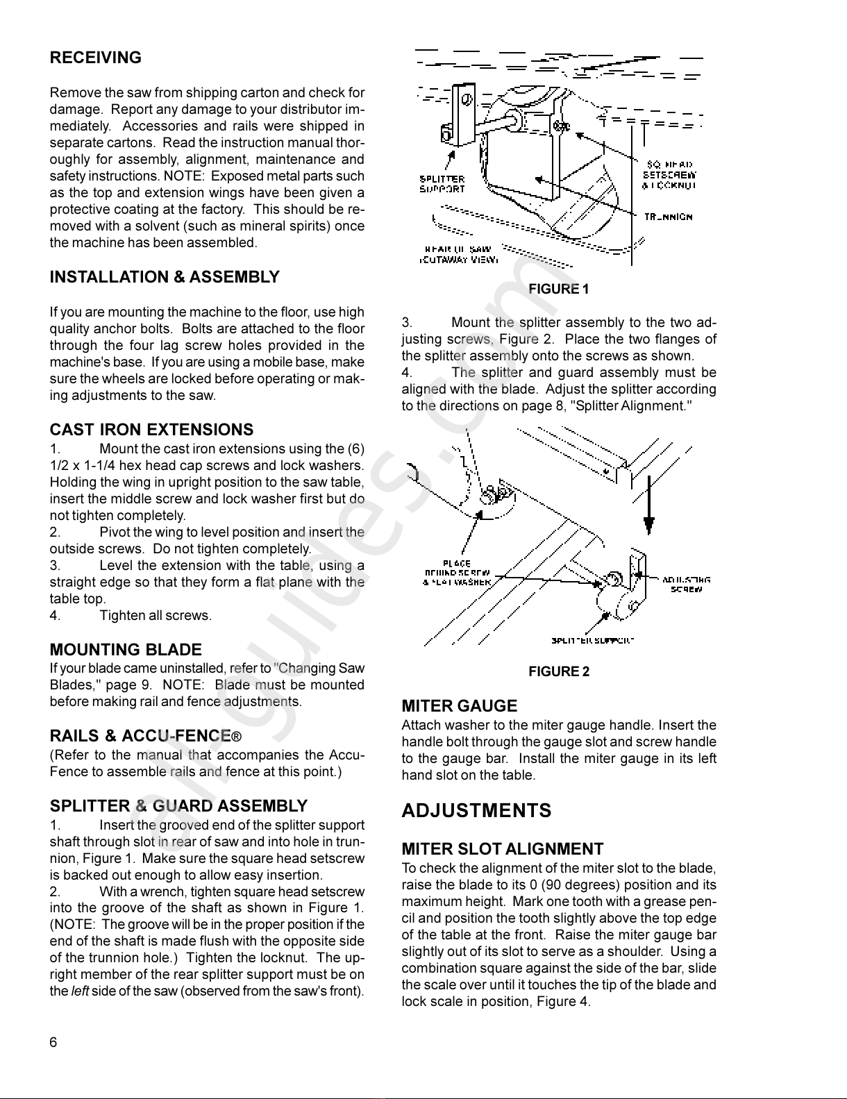
INSTRUCTIONS & PROCEDURES
FOR CIRCULAR SAW
OPERATIONS
GENERAL INSTRU TIONS
1. Familiarize yourself with the location and
operation of all controls and adjustments and the use
of accessories such as the miter gauge and rip fence.
2. Serious injury can result from kickbacks
which occur when a work piece binds on the saw blade
or binds between the saw blade and rip fence or other
fixed object. This binding can cause the work piece
to lift up and be thrown toward the operator. Listed
below are the conditions which can cause kickbacks:
a. Confining the cutoff piece when crosscut-
ting or ripping.
b. Releasing the work piece before complet-
ing the operation or not pushing the work piece
all the way past the saw blade.
c. Not using the splitter when ripping or not
maintaining alignment of the splitter with the saw
blade.
d. Using a dull saw blade.
e. Not maintaining alignment of the rip fence
so that it tends to angle toward rather than away
from the saw blade front to back.
NOTE: Caution decal on guard and splitter as-
sembly.
f. Applying feed force when ripping to the
cutoff (free) section of the work piece instead of
the section between the saw blade and fence.
Use push sticks or push blocks, Figure 13, for
narrow, thin, or short work.
g. Ripping wood that is twisted (not flat), or
does not ha e a straight edge, or a twisted grain.
FIGURE 13
3. To minimize or pre ent injury from kickbacks:
a. A oid conditions listed abo e.
b. Wear a safety face shield, goggles, or
glasses.
c. Do not use the mitre gauge and rip fence
in the same operation unless pro ision is made
by use of a facing board on the fence so as to
allow the cutoff section of the workpiece to come
free before the next cut is started (See pg. 12
for instruction on cross-cutting).
d. Check the operation of the anti-kickback
pawls before starting a cut. If the pawls do not
stop the re erse motion of a workpiece, resharpen
all the points.
e. Where possible, keep your face and body
out of line with potential kickbacks including
when starting or stopping the machine.
4. Dull, badly set, improper, or improperly filed
cutting tools and cutting tools with gum or resin ad-
hering to them cause many of the tilting arbor saw
accidents. Ne er use a cracked saw blade. The use
of a sharp, well maintained, and correct cutting tool
for the operation will help to a oid injuries.
5. Support the work properly and hold it firmly
against the gauge or fence. Use a push stick or push
block when ripping short, narrow (6" width or less), or
thin work. Use a push block or miter gauge hold-
down when dadoing or molding.
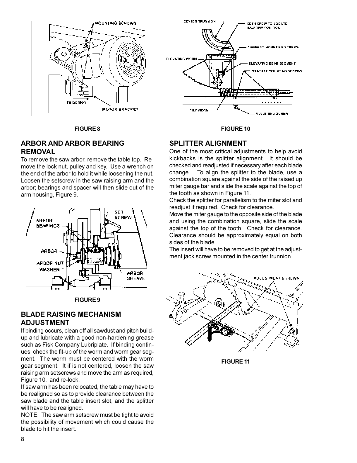
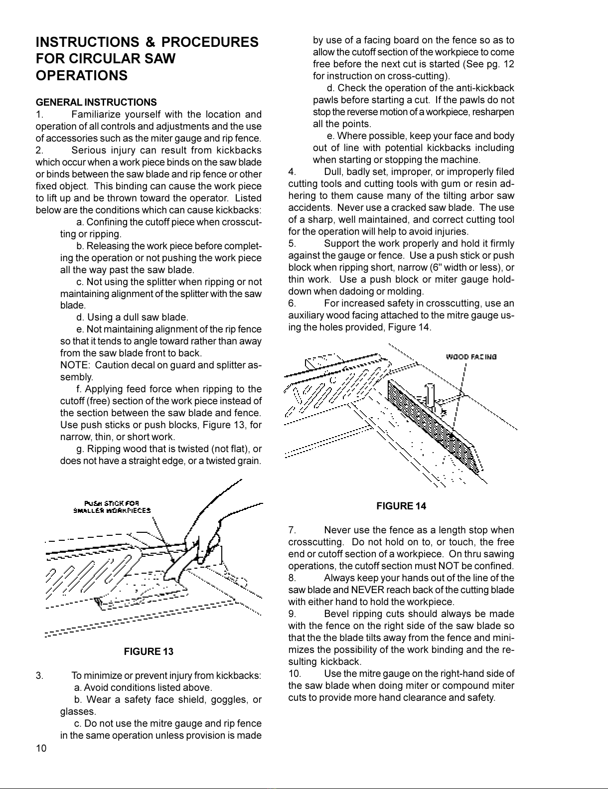
6. For increased safety in crosscutting, use an
auxiliary wood facing attached to the mitre gauge us-
ing the holes pro ided, Figure 14.
FIGURE 14
7. Ne er use the fence as a length stop when
crosscutting. Do not hold on to, or touch, the free
end or cutoff section of a workpiece. On thru sawing
operations, the cutoff section must NOT be confined.
8. Always keep your hands out of the line of the
saw blade and NEVER reach back of the cutting blade
with either hand to hold the workpiece.
9. Be el ripping cuts should always be made
with the fence on the right side of the saw blade so
that the the blade tilts away from the fence and mini-
mizes the possibility of the work binding and the re-
sulting kickback.
10. Use the mitre gauge on the right-hand side of
the saw blade when doing miter or compound miter
cuts to pro ide more hand clearance and safety.
All manuals and user guides at all-guides.com

11
RIP SAWING
1. Ripping is a sawing process where the work
piece is fed with the grain into the saw blade using
the fence as a guide and a positioning de ice to en-
sure the desired width of cut, Figure 15.
FIGURE 15
AUTION: Before starting a ripping cut, be sure
the fence is clamped securely and aligned properly.
Never rip freehand or use the miter gauge in
combination with the fence.
Never rip workpieces shorter than the saw
blade diameter.0
Never reach behind the blade with either hand
to hold down or remo e the cutoff piece with the saw
blade rotating.
2. Always use the saw guard, splitter and kick-
back pawls. Make sure the splitter is properly aligned.
When wood is cut along the grain, the kerf tends to
close and bind on the blade and kickbacks can oc-
cur.
NOTE: A caution decal is installed on the guard and
splitter assembly warning of the hazard of misalign-
ment (see pg. 8 for alignment instructions).
3. The rip fence should be set for the width of
the cut by using the scale on the front rail or by mea-
suring the distance between the blade and fence.
Stand out of line with the saw blade and workpiece to
a oid sawdust and splinters coming off the blade and
a kickback, if one should occur.
4. If the work piece does not ha e a straight
edge, nail an auxiliary straight edged board on it to
pro ide one against the fence. To cut properly, the
board must make good contact with the table. If it is
warped, turn the hollow side down.
5. In ripping, use one hand to hold the board
down against the fence or fixture, and the other to
push it into the blade between the blade and the fence.
If the workpiece is narrow (less than 6") use a push
stick or push block. Ne er push in a location such
that the pushing hand is in line with the blade. Mo e
the hand ser ing as a holddown a safe distance from
the blade as the cut nears completion.
For ery narrow ripping where a push stick cannot be
used, use a push block or auxiliary fence. Always
push the workpiece completely past the blade at the
end of a cut to minimize the possibility of a kickback.
6. When ripping long boards, use a support at
the front of the table and a support or "tailman" at the
rear as shown in Figure 16.
FIGURE 16
7. For work shorter than 12" or narrower than
6", use a push stick or block to push it through be-
tween the fence and the saw blade.
8. Ne er use the rip fence beyond the point where
the carriage is flush with the end of the rails.
9. Ha e the blade extend about 1/8" abo e the
top of the workpiece. Exposing the blade abo e this
point can be hazardous.
RESAWING
1. Resawing is a ripping operation in which thick
boards are cut into thinner ones. Narrow boards up
to 3" can be resawed in one pass. Wider boards up
to 6" must be resawed in two passes.
2. In resawing wider boards, adjust the blade
height so as to o erlap the two cuts by 1/2" as shown
in Figure 17. Too deep a first cut can result in binding
and possible kickbacks on the second cut. Always
use the same side of the board against the fence for
both cuts.
FIGURE 17
All manuals and user guides at all-guides.com
all-guides.com

12
ROSS UTTING
1. The sawing process where the workpiece is
fed cross grain into the saw blade using the mitre
gauge to support and position the workpiece is called
crosscutting, Figure 18. Crosscutting should never
be done freehand nor should the fence be used as an
end stop unless an auxiliary block is clamped to the
front of the blade area such that the cutoff piece comes
free of the block before cutting starts. Length stops
should not be used on the free end of the workpiece
in the cutoff area.
Do not crosscut workpieces shorter than 6". Before
starting a cut, be sure the mitre gauge is securely
clamped at the desired angle. Hold the workpiece
firmly against the table and back against the miter
gauge. Always use the saw guard and splitter and
make sure the splitter is properly aligned.
FIGURE 18
2. For 90 degree crosscutting, most operators
prefer to use the left-hand mitre gauge slot as shown
in Figure 18. When using it in this position, hold the
workpiece against the gauge with the left hand and
use the right hand to ad ance the workpiece. When
using the right hand slot for mitre and compound cross-
cutting so that the blade tilts away from the gauge,
the hand positions are re ersed.
3. When using the mitre gauge, the workpiece
must be held firmly and ad anced smoothly at a slow
rate. If the workpiece is not held firmly, it can ibrate
causing it to bind on the blade and dull the saw teeth.
4. To impro e the effecti eness of the mitre
gauge in crosscutting, some users mount an auxil-
iary wooden extension face (with a glued-on strip of
sandpaper) to the mitre gauge as shown in Figure 19.
5. Pro ide auxiliary support for any workpiece
extending beyond the table top with a tendency to
sag and lift up off the table.
6. Stop rods can be used in the holes pro ided
in the mitre gauge for repetiti e work of equal length.
Do not use a stop rod on the free end of a workpiece.
It should be used on the side of the mitre gauge oppo-
site the saw blade.
FIGURE 19
7. Ha e the blade extend about 1/8" abo e the
top of the workpiece. Exposing the blade abo e this
point can be hazardous.
BEVEL & MITRE OPERATIONS
1. A be el cut is a special type of operation
where the saw blade is tilted at an angle less than 90
degrees to the table top. Operations are performed in
the same manner as ripping or crosscutting except
the fence or mitre gauge should be used on the right-
hand side of the saw blade to pro ide added safety in
a oiding a binding action between the saw blade and
the table top. When be eling with the mitre gauge,
the workpiece must be held firmly to pre ent creep-
ing.
2. Crosscuts made at an angle to the edge of
the workpiece are called miters. Set the mitregauge
at the required angle, lock the mitre gauge, and make
the cut the same as a normal crosscut except the
workpiece must be held extra firmly to pre ent creep-
ing.
3. Ha e the blade extend only 1/8" abo e the
top of the workpiece. Exposing the blade abo e this
point can be hazardous.
All manuals and user guides at all-guides.com

13
Trouble-Shoot ng for Model 72A Table Saw
PROBLEM POSSIBLE AUSE SOLUTION
Excessi e Vibration. 1. Tilt or raising clamp knobs not tightened. 1. Tighten knobs.
2. Blade out of balance. 2. Change blade.
3. Bad motor. 3. Replace motor.
4. Loose arbor or motor shea e. 4. Tighten set screws.
Cuts out-of-square when 1. Mitre gauge out of adjustment. 1. Reset stops and pointer.
crosscutting. 2. Mitre slot misaligned. 2. Realign table.
Motor stalls or workpiece 1. Excessi e feed. 1. Reduce feed.
binds or burns. 2. Bad motor. 2. Replace motor.
3. Dull or incorrect blade. 3. Replace blade.
4. Mitre slot misaligned. 4. Realign mitre slot.
5. Fence misalignment. 5. Realign fence.
Cuts not true at 90 or 45 1. Stop screws not set properly. 1. Readjust set screws.
degrees.
Tilt or saw raising 1. Clamp knobs not released. 1. Unclamp.
handwheels difficult to turn. 2. Worm and worm gear segment caked 2. Clean and re-grease.
with sawdust and pitch.
3. Worm and worm gear segment out of 3. Realign worm and worm
alignment. gear segment.
Motor o erheats. 1. Motor o erloaded. 1. Correct o erload condition
such as reducing the
feed rate.
2. Improper cooling of motor. 2. Clean sawdust from fan
and duct areas of motor.
Motor starts slowly or fails 1. Low oltage. 1. Request oltage check
to come up to full speed. from power company and
correct low oltage
condition.
2. Centrifugal switch not operating. 2. Replace switch.
3. Bad motor. 3. Replace motor.
Motor fails to de elop full 1. Power line o erloaded. 1. Correct o erload condition.
power. 2. Undersize wires in supply system. 2. Increase supply wire size.
3. Low oltage. 3. Request oltage check
from power company and
correct condition.
4. Bad motor. 4. Replace motor.
All manuals and user guides at all-guides.com

14
FEATHER BOARD CONSTRUCTION
The Feather Board is to be made of straight grain hardwood approximately 1" thick and 4" to 8" wide
according to the size of the machine. The length sho ld be developed in accordance with its intended
se. Feather Boards can be fastened to the table or rip fence by the se of "C" clamps. Drilled and
tapped holes in the table top allow for the se of wing n ts and washers as a method of clamping.
Provide slots in the Feather Board for adj stments if this method of clamping is sed. Fig re 18 shows a
method of attaching and se of Feather Boards as a vertical comb. The horizontal application is essen-
tially the same except the attachment is to the table top.
FILLER PIECE CONSTRUCTION
PUSH STICK & PUSH BLOCK CONSTRUCTION
FIGURE 18
All manuals and user guides at all-guides.com

15
NO. PART NO. DESCRIPTION
2471015 Mitre Gauge Assembly (Items 1
thru 14)
1 3044053 Mitre Gauge Bar
2 3230038 Mitre Gauge
3 3604035 Mitre Gauge P inter
4 3585221 St p Pin
5 3841202 Mitre Gauge Bar Washer
6 6506001 Hex Nut, 6-32
PARTS LIST: Mitre Gauge Assemb y 2471015
NO. PART NO. DESCRIPTION
7 6623012 D wel Pin, 1/4 X 1
9 6706015 Fillister Head Machine Screw,
6-32 X 5/8
11 6714053 Flat Head Cap Screw, 1/4-20 X 3/8
12 6861101 Plain Flat Washer, 1/4
13 3695221 L cking Screw, 1/4 X 3-3/8
14 3268050 Mitre Gauge Handle Kn b
15 3055435 P inter Bl ck
All manuals and user guides at all-guides.com

16
NO. PART NO. DESCRIPTION
1 2104031 M t r C ver
2 2759040 Stand Assembly (Weldment)
5 6440003 D r Latch
6 3136018 Dust Rem val D r
7 3186005 11" R und Extensi n
8 3328073 Table Insert
12 3604003 Saw Tilting P inter
14 3684217 Scale
15 3703003 3/8 Diameter Shaft
16 3797424 T.A. Saw Table
18 6708012 R und Head Machine Screw,
8-32 X 1/4
PARTS LIST: Stand Assemb y
NO. PART NO. DESCRIPTION
19 6714049 Hex Head Screw, 1/4-20 X 3/4
20 6714081 Sl t Head Steel Set Screw
1/4-20 X 3/8
22 6718009 Hex Head Cap Screw,
1/2-13 X 1-1/4
23 6746001 Pan Head Self-Tapping Screw,
6 X 1/4
24 6861500 Helical Spring L ck Washer, 1/2
25 3328075 Dad Insert
26 6515001 Hex Nut, 5/16-18
27 6715101 Square Head Screw
2136002 D r Assembly
All manuals and user guides at all-guides.com
all-guides.com

17
EXPLODED VIEW: Stand Assemb y
All manuals and user guides at all-guides.com

18
NO. PART NO. DESCRIPTION
1 3025264 Bearing Arm
2 6716003 S cket Set Screw, 3/8-16 X 3/8
3 3773325 Stud, 1/2-13 X 2-5/8 D uble End
4 6716006 S cket Set Screw, 3/8-16 X 1-1/4
5 6716081 Square Head Set Screw
6 6516009 Jam Nut, 3/8-16
2024020 Arb r Assembly (Items 7 and 9 thru
12 & 54)
7 3838007 Saw Arb r C llar
8 6420002 608 W druff Key, #13
9 6060010 D uble Seal Ball Bearing, 205NPP
10 6670005 Retaining Ring, #5100-100
11 3737215 Bearing Spacer
12 6863005 Washer
13 3717167 Arb r Sheave
14 6715013 Steel Set Screw, 5/16-18 X 3/8
15 3237034 Segment W rm Gear
16 6861301 Flat Washer, 3/8
17 6861300 Helical Spring L ck Washer, 3/8
18 6716032
Hex Head Screw, 3/8-16 X 1-1/2
2865004 Saw Raising W rm Assembly
(Items 19, 20 & 21)
19 3865001 Saw Raising & Tilting W rm
20 3701027 Saw Raising W rm Shaft
21 6626031 Spring Pin, 3/16 X 1-1/8
2271008 Handwheel Assembly (Items 23, 24
& 41)
23 6350032 Handle Assembly
24 3271039 Handwheel, 8 X 3/4
2440009 Raise & Tilt L ck Assembly
(Items 25 & 26)
25 3583011 Saw Raising & Tilting L cating Pin
PARTS LIST: Arbor
NO. PART NO. DESCRIPTION
26 3406018 #801 Black Phen lic Kn b, .382
27 6716082 Square Head Set Screw,
3/8-16 X 2-1/2
29 3711005 Saw Arm Piv t Shaft
30 6526005 Jam Nut, 1"-8 R.H.
32 3090012 Dust Chute
33 6714127 Hex Head Screw, 1/4-20 X 1/2
34 6861100 Helical Spring L ck Washer, 1/4
35 3480015 M t r M unt
36 6718017 Hex Head Cap Screw 1/2-13 X 1-3/4
37 6861501 Flat Washer, 1/2
38 6861500 Helical Spring L ck Washer, 1/2
39 6861901 Flat Nyl n Washer, 3/4
40 3096004 Saw Raising C llar
41 6715015 S cket Head Set Screw,
5/16-18 X 1/4
43 6716031 Hex Head Screw, 3/8-16 X 1
44 6861300 Helical Spring L ck Washer 3/8
46 6715016 S cket Head Cup P int Set Screw,
5/16-18 X 5/16
47 6077169 Vee Belt, 3VX250 (matched 3
required)
6472327 M t r, 5HP, 3 Ph, 200V
6472335 M t r, 5HP, 1 Ph
6472307 M t r, 5HP, 3 Ph
6472504 M t r, 7.5 HP, 3 Ph
51 6578003 Hex Nut, 3/8-16
52 6670092 Ext. Retaining Ring, 5107-112
53 6715013 S cket Head Set Screw
54 3700124 Saw Arb r Shaft
55 6716093 Nyl k Set Screw, 3/8-16 x 1
All manuals and user guides at all-guides.com

19
EXPLODED VIEW: ARBOR
All manuals and user guides at all-guides.com

20
NO. PART NO. DESCRIPTION
2271008 Handwheel Assembly, 8" Diameter
1 6350032 Handle Assembly
3 3271039 Handwheel, 8" Diameter
2440009 Saw Raising & Tilting Cup P int
L ck Assembly (Items 4 & 5)
4 3583011 L cking Pin
5 3406018 Kn b
2063017 Saw Tilting Bracket Assembly
(Items 6 thru 14)
2865006 Saw Tilting W rm Assembly
(Items 6 thru 8)
6 3865001 Saw Raising & Tilting W rm
7 3701026 Saw Tilting Shaft
8 6626031 Spring Pin, 3/16 X 1-1/8
9 3096244 C llar
10 3065006 Saw Tilting Piv t Bracket
11 6861901 Flat Nylatr n Washer E12, 3/4 I.D.
12 6420002 W druff Key, #607 (L cking)
13 6715016 Cup P int S cket Set Screw,
5/16-18 X 1/4" (C llar)
14 6064002 Nice Thrust Bearing #607
15 3810038 H using Trunni n
16 3810023 Fr nt & Rear Trunni n
17 3700090 Splitter Supp rt Shaft, 1"
18 6715039 Hex Head Cap Screw,
5/16-18 X 1-3/4"
19 3750010 Splitter
PARTS LIST: Arbor
NO. PART NO. DESCRIPTION
20 6716082 Square Head Set Screw,
3/8-16 X 2-1/2" (Splitter)
21 6716031 Hex Head Cap Screw, 3/8-16 X 1
(45 degree st p)
22 6516009 Hex Jam Nut, 3/8-16
23 3711005 Saw Arm Piv t Shaft
24 6578003 Flexl c Self-L cking Hex Nut,
1-1/8 - 12
25 6670092 External Retaining Ring
26 3690232 Adjusting Screw, 3/4-16 X 1-1/2
27 6572005 Hex Jam Nut, 3/4-16
28 6516001 Hex Nut, 3/8-16
29 6861309 Plated Flat Washer, 3/8
30 6716039 Hex Head Cap Screw, 3/8-16 X 1-1/4
31 6861300 L ck Washer, 3/8
32 6861301 Flat Washer, 3/8
33 6715013 S cket Set Knurled Screw,
5/16-18 X 3/8
34 3604029 P inter
35 6708012 R und Head Machine Screw,
#8-32 X 1/4
36 6716081 Square Head Set Screw,
3/8-16 X 1-1/2
37 6760078 S cket Set Screw, 10-32 X 3/8
38 6716195 S cket Set Screw, 3/8-16 X 1-1/2
39 6861300 L ck Washer, 3/8
40 6811327 Spacer
All manuals and user guides at all-guides.com
Other manuals for 72A
3
Table of contents
Other Powermatic Industrial Equipment manuals