TCi HarmonicGuard HGP User manual

HarmonicGuard®Series Drive-Applied Harmonic Filter
Installation, Operation, and Maintenance Manual

No part of this publication may be reproduced, stored in a retrieval system, or transmitted in any form or
by any means, mechanical, electronic, photocopying, recording, or otherwise, without the prior written
permission of TCI, LLC. The information in this manual is subject to change without notice. Every
precaution has been taken in the preparation of this manual. TCI, LLC assumes no responsibility for errors
or omissions. Neither is any liability assumed for damages resulting from the use of the information
contained in this publication.

Table of Contents
Introduction..............................................................................................................................5
Receiving Inspection and Storage............................................................................................7
Pre-installation Planning.......................................................................................................... 8
Installation Guidelines.............................................................................................................9
HGP Filter Operation............................................................................................................. 10
Installation .............................................................................................................................11
Maintenance and Service....................................................................................................... 12
Product Description............................................................................................................... 14
Standard Option (S)...............................................................................................................17
Contactor Option (C).............................................................................................................18
Fuse Monitor with Contactor Option (F)..............................................................................19
Fuse Monitor without Contactor Option (G) .......................................................................20
CP Kit Enclosure (8) with Option (0)....................................................................................21
Line Reactor Installation........................................................................................................22
Typical Voltage Distortion Option (0)..................................................................................23
High Voltage Distortion Option (1).......................................................................................24


Introduction
Safety Instructions Overview
This section provides the safety instructions which must be followed when installing, operating, and
servicing the HarmonicGuard Passive (HGP) filter. If neglected, physical injury or death may follow,
or damage may occur to the filter or equipment connected to the HGP filter. The material in this
chapter must be read and understood before attempting any work on, or with, the product.
The HGP filter is intended to be connected to the input terminals of one or more VFDs. Three-phase
power is connected to the input terminals of the HGP and power is supplied to the VFD or VFDs
through the HGP. The instructions, and particularly the safety instructions, for the VFDs, motors, and
any other related equipment must be read, understood, and followed when working on any of the
equipment.
Warnings and Cautions
This manual provides two types of safety instructions. Warnings are used to call attention to
instructions that describe steps that must be taken to avoid conditions that can lead to a serious fault
condition, physical injury, or death.
Cautions are used to call attention to instructions that describe steps that must be taken to avoid
conditions that can lead to a malfunction and possible equipment damage.
Warnings
Readers are informed of situations that can result in serious physical injury and/or serious damage to
equipment with warning statements highlighted by the following symbols:
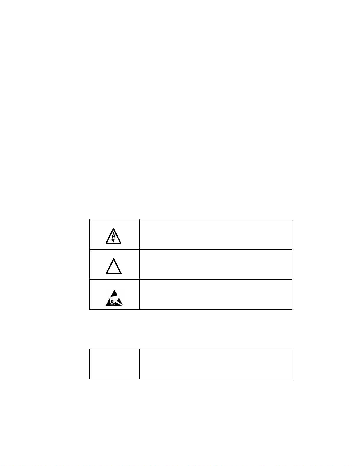
Warning Dangerous Voltage Warning: warns of situations where high
voltage can cause physical injury and/or damage equipment.
The text next to this symbol describes ways to avoid the
danger.
Warning General Warning: warns of situations that can cause physical
injury and/or damage equipment by means other than
electrical. The text next to this symbol describes ways to avoid
the danger.
Warning Electrostatic Discharge Warning: warns of situations in which
an electrostatic discharge can damage equipment. The text next
to this symbol describes ways to avoid the danger.
Cautions
Readers are informed of situations that can lead to a malfunction and possible equipment damage with
caution statements:
Caution General Caution: identifies situations that can lead to a
malfunction and possible equipment damage. The text
describes ways to avoid the situation.
!

General Safety Instructions
These safety instructions are intended for all work on the HGP. Additional safety instructions are
provided at appropriate points on other sections of this manual.
Warning
Be sure to read, understand, and follow all safety instructions.
Warning Only qualified electricians should carry out all electrical
installation and maintenance work on the HGP filter.
Warning All wiring must be in accordance with the National Electrical
Code (NEC) and/or any other codes that apply to the
installation site.
Warning Disconnect all power before working on the equipment.
Do not attempt any work on a powered HGP filter.
Warning The HGP filter, drive, motor, and other connected equipment
must be properly grounded.
Warning After switching off the power, always allow 5 minutes for the
capacitors in the HGP filter and in the drive to discharge before
working on the HGP, the drive, the motor, or the connecting
wiring. It is a good idea to check with a voltmeter to make sure
that all sources of power have been disconnected and that all
capacitors have discharged before beginning work.
!
!
!

Receiving Inspection and Storage
Thank you for selecting the HarmonicGuard Passive (HGP) filter. TCI has produced this filter for use
in many variable frequency drive (VFD) applications that require input power line harmonic current
reduction. This manual describes how to install, operate and maintain the HGP filter.
Receiving Inspection
The HGP filter has been thoroughly inspected and functionally tested at the factory and carefully
packaged for shipment. When you receive the unit, you should immediately inspect the shipping
container and report any damage to the carrier that delivered the unit. Verify that the part number of
the unit you received is the same as the part number listed on your purchase order.
TCI Limited Warranty Policy
TCI, LLC (“TCI”) warrants to the original purchaser only that its products will be free from defects in materials
and workmanship under normal use and service for a period originating on the date of shipment from TCI and
expiring at the end of the period described below:
Product Family
Warranty Period
KLR, KDR
For the life of the drive with which they are installed.
KLC, KLCUL, KMG,
V1k
One (1) year of useful service,
not to exceed 18 months from the date of shipment.
HGP, HG7, KH, 3H, KRF
Three (3) years from the date of shipment.
KCAP, KTR, KMP
Five (5) years from the date of shipment.
All Other Products
One (1) year of useful service,
not to exceed 18 months from the date of shipment.
The foregoing limited warranty is TCI’s sole warranty with respect to its products and TCI makes no other
warranty, representation, or promise as to the quality or performance of TCI’s products. THIS EXPRESS
LIMITED WARRANTY IS GIVEN IN LIEU OF AND EXCLUDES ANY AND ALL EXPRESS OR IMPLIED
WARRANTIES INCLUDING, WITHOUT LIMITATION, ANY IMPLIED WARRANTY OF
MERCHANTABILITY OR FITNESS FOR A PARTICULAR PURPOSE.
This warranty shall not apply if the product was:
a) altered or repaired by anyone other than TCI;
b) applied or used for situations other than those originally specified; or
c) subjected to negligence, accident, or damage by circumstances beyond TCI’s control, including but not
limited to, improper storage, installation, operation, or maintenance.
If, within the warranty period, any product shall be found in TCI’s reasonable judgment to be defective, TCI’s
liability and the Buyer’s exclusive remedy under this warranty is expressly limited, at TCI’s option, to (i) repair or
replacement of that product, or (ii) return of the product and refund of the purchase price. Such remedy shall be
Buyer’s sole and exclusive remedy. TCI SHALL NOT, IN ANY EVENT, BE LIABLE FOR INCIDENTAL
DAMAGES OR FOR CONSEQUENTIAL DAMAGES INCLUDING, BUT NOT LIMITED TO, LOSS OF
INCOME, LOSS OF TIME, LOST SALES, INJURY TO PERSONAL PROPERTY, LIABILITY BUYER
INCURS WITH RESPECT TO ANY OTHER PERSON, LOSS OF USE OF THE PRODUCT OR FOR ANY
OTHER TYPE OR FORM OF CONSEQUENTIAL DAMAGE OR ECONOMIC LOSS.
The foregoing warranties do not cover reimbursement for removal, transportation, reinstallation, or any other
expenses that may be incurred in connection with the repair or replacement of the TCI product.
The employees and sales agents of TCI are not authorized to make additional warranties about TCI’s products.
TCI’s employees and sales agents oral statements do not constitute warranties, these shall not be relied upon by
the Buyer, and are not part of any contract for sale. All warranties of TCI embodied in this writing and no other
warranties are given beyond those set forth herein.
TCI will not accept the return of any product without its prior written approval. Please consult TCI Customer
Service for instructions on the Return Authorization Procedure.
Storage Instructions
If the HGP filter is to be stored before use, be sure that it is stored in a location that conforms to
published storage humidity and temperature specifications stated in Table 2 (HarmonicGuard Passive
Filter Technical Specifications). Store the unit in its original packaging.

Pre-installation Planning
Verify the Application
HGP Ratings
Make sure that the HGP filter is correct for the application. The voltage ratings of the filter must match
the input voltage rating of the connected drive. The horsepower and current ratings of the filter must be
appropriate for the connected load.
Select a Suitable Location
Environment
Locating the HGP in a suitable environment will help ensure proper performance and a normal
operating life. Refer to the environmental specifications listed in Table 2, marked on the unit's
nameplate, and/or noted on the drawings furnished with the unit.
Warning Unless specifically labeled as approved for such use, this equipment is not
suitable for use in an explosive atmosphere or in a "Hazardous (Classified)
Location" as defined in article 500 of the National Electrical code.
The unit must be installed in an area where it will not be exposed to:
♦Direct sunlight
♦Rain or dripping liquids (unless filter is in a Type 3R enclosure)
♦Corrosive liquids or gasses
♦Explosive or combustible gases or dust
♦Excessive airborne dirt and dust
♦Excessive vibration
Working Space
Provide sufficient access and working space around the unit to permit ready and safe installation,
operation and maintenance. Make sure that the installation conforms to all working space and
clearance requirements of the National Electrical Code (NEC) and/or any other applicable codes.
Provide sufficient unobstructed space to allow cooling air to flow through the unit.
Mounting an Open Panel Unit
If you are mounting an open panel unit in your own enclosure, you must provide an enclosure that is
adequately sized and ventilated sufficiently to prevent overheating. The rating and dimension tables for
open panel units list the watts of heat loss dissipated by the HGP filter. The maximum temperature of
the air around the HGP filter capacitors, line reactor, and tuning reactor should not exceed 50°C
(122°F).
Power Wiring
When selecting a mounting location for the HGP filter, plan for the routing of the power wiring.
Route the conduit and wiring from the power source to the filter and then to the VFD.
The HGP is provided with internal fuses.
!

Installation Guidelines
Mounting
The HGP must be mounted vertically on a smooth, solid surface, free from heat, dampness, and
condensation.
Wiring
Cable Entry Locations
The enclosed HGP filters are not provided with enclosure wiring knockouts. A location can be selected
at the time of installation. Typical or recommended cable entry locations are shown in the drawings
section of this manual.
Field Wiring Connection Terminals
Compression type terminals are provided for all field wiring connections. The wire size capacity
ranges and tightening torques for all field wiring connections are listed in the drawings and other
information shipped with the unit.
Grounding
The HGP panel equipment-grounding lug must be connected to the ground of the wiring system. The
equipment-grounding connection must conform to the requirements of the National Electric Code
(NEC) and/or any other codes that apply to the installation site. The ground connection must be made
using a wire conductor. Metallic conduit is not a suitable grounding conductor. The integrity of all
ground connections should be periodically checked.
Power Wiring
Caution Use copper wire that is appropriate for the voltage and current rating of the
equipment. The wire selection must conform to the requirements of the
National Electrical Code and/or other applicable electrical codes.
For units rated less than 100 amps, use wire with an insulation temperature
rating of 60°C or higher.
For units rated 100 amps or more, use wire with an insulation temperature
rating of 75°C or higher.
Connect three-phase power of the appropriate voltage and current capacity to the circuit protective
device to the HGP input power terminals.
Note: in large units, the input power conductors are connected directly to the input terminals on the
line reactors.
Connect the output terminals of the HGP to the input power terminals of the VFD.
Note: in large units, the output power conductors are connected directly to the output terminals on the
line reactors. Refer to the VFD installation instructions for additional information.

HGP Filter Operation
Caution Thoroughly check the installation before applying power and operating
the equipment for the first time.
Before Applying Power for the First Time
Inspect the installation to make sure that all equipment has been completely and correctly installed in
accordance with the Installation Guidelines section of this manual.
♦Check to see that the cooling fan(s) are operating in units so equipped.
♦Check to make sure power connections are torqued to recommended torque value.
Operation
Since the HGP is a passive filter, it is always operating whenever the drive is operating.

Installation
Intended Audience
This manual is intended for use by all personnel responsible for the installation, operation and
maintenance of the HGP filters. Such personnel are expected to have knowledge of electrical wiring
practices, electronic components and electrical schematic symbols.
Additional Information
Caution This manual provides general information describing your HGP
filter. Be sure to
carefully review the more specific information that is provided by the drawings
shipped with the unit. Information provided by the drawings takes precedence
over the information provided in this manual.
The ratings, dimensions and weights given in this manual are approximate and
should not be used for any purpose requiring exact data. Contact the factory in
situations where certified data is required. All data is subject to change without
notice.
Installation Checklist
The following are the key points to be followed for a successful installation. These points are
explained in detail in the following sections of this manual.
Make sure that the installation location will not be exposed to direct sunlight, corrosive or
combustible airborne contaminants, excessive dirt or liquids.
Select a mounting area that will allow adequate cooling air and maintenance access.
Make sure that all wiring conforms to the requirements of the National Electric Code (NEC)
and/or other applicable electrical codes.
Connect the HGP equipment-grounding lug to the system ground of the premises wiring system.
Use a properly sized grounding conductor.
Connect three-phase power to the input terminals of the HGP, L1, L2 & L3.
Connect the output power terminals, of the HGP, T1, T2 & T3, to the input power terminals of
the VFD.

Maintenance and Service
HGPFilter Reliability and Service Life
The HGP has been designed to provide a service life that equals or exceeds the life of the VFD. It has
been thoroughly tested at the factory to assure that it will perform reliably from the time it is put into
service. It is recommended that the following maintenance be done once a year to ensure that the
HGP filter will always perform reliably and provide the expected service life.
Periodic Maintenance
Warning Only qualified electricians should carry out all electrical installation and
maintenance work on the HGP filter.
Disconnect all sources of power to the drive and HGP before working on the
equipment. Do not attempt any work on a powered HGP.
Check to see that the installation environment remains free from exposure to excessive dirt and
contaminants. Refer to the Pre-installation Planning section of this manual.
Check to make sure that the enclosure ventilation openings are clean and unobstructed.
Clean the air filter in units that have filtered air inlets. Clean as often as necessary to prevent dirt build-
up from impeding air flow.
Check the operation of the cooling fan.
Inspect the interior of the enclosure for signs of overheated components. Clean the interior of the
enclosure whenever excess dirt has accumulated.
Torque all power wire connections, loose connections can overheat and damage the filter.
Troubleshooting
Warning Only qualified electricians should carry out all electrical installation and
maintenance work on the HGP filter.
Disconnect all sources of power to the drive and HGP before working on the
equipment. Do not attempt any work on a powered HGP filter.
The harmonic filter contains high voltages and capacitors. Wait at least five
minutes after disconnecting power from the filter before you attempt to
service the harmonic filter. Check for zero voltage between all terminals on
the capacitors. Also, check for zero voltage between all phases of the line side
of the fuses, Fu1(a)–Fu2(a)–Fu3(a), and all input terminals L1, L2 and L3 of
the line reactor (KDR). All setup, maintenance, and troubleshooting must be
done by a qualified electrician. Failure to follow standard safety procedures
may result in death or serious injury.
Note: when disconnecting wires from components and terminations, mark the wires to correspond to
their component and terminal connection.

Replacement Parts
If replacement parts are needed, please contact your TCI representative. To ensure that the HGP filter
continues to perform to its original specifications, replacement parts should conform to TCI
specifications.
Factory Contacts and Tech Support
For technical support, contact your local TCI distributor or sales representative.
You can contact TCI directly at 800-TCI-8282. Select "Customer Service" or "Tech Support" and have
your HGP filter nameplate information available.

Product Description
HGP Drive-Applied Filter
The HGP is a drive-applied harmonic filter designed and developed by TCI to reduce the harmonic
currents drawn from the power source by VFDs. It is suitable for use with 3-phase diode bridge
rectifier loads such as PWM AC drives. SCR or thyristor loads such as DC drives would require a
different filter configuration outside the scope of this product offering. Please contact TCI Technical
Support for additional information.
The HGP is a passive filter connected in series with the input terminals of a VFD or several VFDs that
operate as a group. It is designed to provide a low impedance path for the major harmonic currents
demanded by the drive. The filter is a stand-alone device that can be furnished in its own enclosure and
mounted adjacent to the drive. It is also available on an open panel for mounting within an enclosure
with the drive or other equipment.
The HGP filters consist minimally of the following features and components:
♦A KDR tuned series reactor to prevent system interaction and improve filter performance
♦An L-C-L filter circuit with:
A TCI 3-phase tuning reactor specifically designed for the HGP filter
High-endurance, harmonic-rated capacitors
♦Bleeder resistors to ensure safe capacitor discharge upon filter shutdown
♦Cooling fans (on select models) to ensure adequate cooling and safe operating
temperatures
♦Compression terminals for ease and integrity of all power and control wiring
♦Fuses, sized to protect the capacitor wiring
Nameplate Data
The following information is marked on the nameplate:
• Part number: encoding is explained on the following page
• FLA: the rated continuous operating current (RMS amps)
• System Voltage: the rated 3-phase line voltage (RMS volts)
• Hz: the rated frequency (60 Hz)
• Phase: 3 – The HGP filter is designed for use only with 3-phase power.
• Drawing #: outline and mounting dimension drawing number
• Schematic #: schematic diagram drawing number
• Manufacturing #: for TCI internal use
• Enclosure Type: UL designation or "Open" panel construction

Part Number Encoding
Figure identifies the significance of each character in the HGP part number. The example part number,
HGP0150AW1S0000 designates an HGP filter that is rated 150 HP, 480 volts, 60 Hz. It includes a line
reactor, tuning reactor, and capacitors in a UL Type 1 enclosure. It is designed for use with a 150 HP
drive.
Figure 1 – HGP Part Number Encoding
F
G
Option:
0
- Standard
0
- Standard
Option:
0
- Typical Voltage Distortion
Option:
1
- High Voltage Distortion
0
0
Option:
0
- Standard
Option:
- Fuse Monitor with Contactor
- Fuse Monitor without Contactor
W
- 60 Hz
Enclosure:
0
- Open
Frequency:
Horse Power:
Voltage Rating:
A - 480 V
0
0
0
Series:
A
W
1
S
P
1
5
0
G
H
1
- Type 1
C
- Contactor
S
- Standard
3
- Type 3R

Product Technical Specifications
Table 1 lists the major technical sp0ecifications for the HGP Filter.
Table 1 – HGP Technical Specifications
Voltage ratings 480V, 3 phase, 60 Hz
kVar ratings 1.3 to 270 kVar depending on voltage.
Load types 3-phase diode bridge rectifier loads such as PWM AC drives
Load power range 5 -900 HP
Current ratings The included series reactors can tolerate 200% of rated current for at
least 3 minutes.
SCCR (short circuit current
rating) Standard rating is 100kA.
Maximum elevation 3,000 feet (1,000 meters) as standard.
Maximum ambient operating
temperature 50°C (122°F) – Open Panel; 40°C (104°F) – Enclosed Panel.
Product must be equipped with special cooling provisions for
operation above this temperature.
Maximum ambient storage
temperature 60°C (140°F)
Maximum humidity,
operating or storage 95%, non-condensing.
Enclosure options UL Type 1 enclosure
UL Type 3R enclosure
Agency approvals or
certifications UL and cUL Listed to UL508A
Insertion Impedance +/- 10% at full load current
Fusing and protection: All units have internal fuse protection for the harmonic filter circuit.

Standard Option (S)
The Standard Option includes very high quality harmonic-grade capacitors and line reactors. This filter
will meet the majority of application requirements found today. This cost effective product is available
as an open panel version, in a UL Type 1 enclosure, or in an UL Type 3R enclosure. The open panel is
perfect for inclusion in a MCC section or easy installation into industry standard enclosures. The UL
Type 1 enclosed units maintain the same vertical profile as the open panel design. This design is
perfect for applications where floor space is at a premium. The UL Type 3R enclosure protects the
filter from harsh conditions.
Product Description
HGPSOption Filter
The HGP harmonic filter is a drive-applied harmonic filter designed and developed by TCI to reduce
the harmonic currents drawn from the power source by VFDs. The HGP harmonic filter is for 480 volt
systems (60 Hz). It is suitable for use with 3-phase diode bridge rectifier loads such as PWM AC
VFDs.
The HGP harmonic filter is a passive filter connected in series with the input terminals of a VFD or
several VFDs that operate as a group. It is designed to provide a low impedance path for the major
harmonic currents demanded by the VFD. The filter is a stand-alone device that can be furnished in its
own enclosure and mounted adjacent to the VFD. It is also available on an open panel for mounting
within an enclosure with the VFD or other equipment.
The HGP Standard Option consists of the following standard features and components:
♦A KDR tuned series reactor.
♦A TCI 3-phase tuning reactor specifically designed for the HGP filter.
♦High-endurance, harmonic-rated capacitors.
♦Bleeder resistors to ensure safe capacitor discharge upon filter shutdown, located on
capacitors.
♦Cooling fans (on select models) to ensure adequate cooling and safe operating
temperatures.
♦Control Power transformer on enclosed units requiring auxiliary cooling fans.
♦Compression terminals for ease and integrity of all power and control wiring.
♦Fuses

Contactor Option (C)
The Contactor Option includes a contactor, control power transformer and connection terminals in the
filter circuit which allows the VFD user to control the insertion of this circuit through the use of a relay
contact in the VFD. It is recommended that the VFD contact be programmed to open the contactor
below 33% motor power. For variable torque (fan) loads this will be approximately below 70% speed,
so the at-speed contact may be used. This reduces the possibility of leading power factor interacting
with other devices on the power system. Contactor logic should also maintain the contactor closed in
cases where the VFD is bypassed and the filter is not bypassed.
Product Description
HGP COption Filter
The HGP harmonic filter is a drive-applied harmonic filter designed and developed by TCI to reduce
the harmonic currents drawn from the power source by VFDs. The HGP harmonic filter is for 480 volt
systems (60 Hz). It is suitable for use with 3-phase diode bridge rectifier loads such as PWM AC
VFDs.
The HGP harmonic filter is a passive filter connected in series with the input terminals of a VFD or
several VFDs that operate as a group. It is designed to provide a low impedance path for the major
harmonic currents demanded by the VFD. The filter is a stand-alone device that can be furnished in its
own enclosure and mounted adjacent to the VFD. It is also available on an open panel for mounting
within an enclosure with the VFD or other equipment.
The HGP Contactor Option consists of the following standard features and components:
♦A KDR tuned series reactor.
♦A TCI 3-phase tuning reactor specifically designed for the HGP filter.
♦High-endurance, harmonic-rated capacitors.
♦Bleeder resistors to ensure safe capacitor discharge upon filter shutdown, located on
capacitors.
♦Filter enable/disable contactor with protection and drive interlock provisions.
♦Cooling fans (on select models) to ensure adequate cooling and safe operating
temperatures.
♦Control power transformer
♦Compression terminals for ease and integrity of all power and control wiring.
♦Fuses
♦Contactor

Fuse Monitor with Contactor Option (F)
The Fuse Monitor with Contactor Option includes a voltage monitor module and relay that can be
connected to a VFD or other device. The fuse monitor will indicate a fuse failure and communicate this
condition through the relay to a connected device.
This option includes a contactor, control power transformer, and connection terminals in the filter
circuit which allows the VFD user to control the insertion of this circuit through the use of a relay
contact in the VFD. It is recommended that the drive contact be programmed to open the contactor
below 33% motor power. For variable torque (fan) loads this will be approximately below 70% speed,
so the at-speed contact may be used. This reduces the possibility of leading power factor interacting
with other devices on the power system. Contactor logic should also maintain the contactor closed in
cases where the VFD is bypassed and the filter is not bypassed.
Product Description
HGP FOption Filter
The HGP harmonic filter is a drive-applied harmonic filter designed and developed by TCI to reduce
the harmonic currents drawn from the power source by VFDs. The HGP harmonic filter is for 480 volt
systems (60 Hz). It is suitable for use with 3-phase diode bridge rectifier loads such as PWM AC
drives.
The HGP harmonic filter is a passive filter connected in series with the input terminals of a VFD or
several VFDs that operate as a group. It is designed to provide a low impedance path for the major
harmonic currents demanded by the VFD. The filter is a stand-alone device that can be furnished in its
own enclosure and mounted adjacent to the VFD. It is also available on an open panel for mounting
within an enclosure with the VFD or other equipment.
The HGP F Option consists of the following standard features and components:
♦A KDR tuned series reactor.
♦A TCI 3-phase tuning reactor specifically designed for the HGP filter.
♦High-endurance, harmonic-rated capacitors.
♦Bleeder resistors to ensure safe capacitor discharge upon filter shutdown, located on
capacitors.
♦Filter enable/disable contactor with protection and drive interlock provisions.
♦Cooling fans (on select models) to ensure adequate cooling and safe operating
temperatures.
♦Control power transformer
♦Compression terminals for ease and integrity of all power and control wiring.
♦Fuses
♦Contactor
♦Voltage monitor module to report status of fuses to control

Fuse Monitor without Contactor Option (G)
The Fuse Monitor without Contactor Option includes a voltage monitor module and relay that can be
connected to a VFD or other device. The fuse monitor will indicate a fuse failure and communicate this
condition through the relay to a connected device.
Product Description
HGP GOption Filter
The HGP harmonic filter is a drive-applied harmonic filter designed and developed by TCI to reduce
the harmonic currents drawn from the power source by VFDs. The HGP harmonic filter is for 480 volt
systems (60 Hz). It is suitable for use with 3-phase diode bridge rectifier loads such as PWM AC
VFDs.
The HGP harmonic filter is a passive filter connected in series with the input terminals of a VFD or
several VFDs that operate as a group. It is designed to provide a low impedance path for the major
harmonic currents demanded by the VFD. The filter is a stand-alone device that can be furnished in its
own enclosure and mounted adjacent to the VFD. It is also available on an open panel for mounting
within an enclosure with the VFD or other equipment.
The HGP G Option consists of the following standard features and components:
♦A KDR tuned series reactor.
♦A TCI 3-phase tuning reactor specifically designed for the HGP filter.
♦High-endurance, harmonic-rated capacitors.
♦Bleeder resistors to ensure safe capacitor discharge upon filter shutdown, located on
capacitors.
♦Cooling fans (on select models) to ensure adequate cooling and safe operating
temperatures.
♦Control Power transformer on enclosed units requiring auxiliary cooling fans.
♦Compression terminals for ease and integrity of all power and control wiring.
♦Fuses
♦Voltage monitor module to report status of fuses to control
This manual suits for next models
1
Table of contents
Other TCi Industrial Equipment manuals
Popular Industrial Equipment manuals by other brands

ATI Technologies
ATI Technologies Flexdeburr 9150-RC-300 Series Installation and operation manual

Clarke
Clarke C18H instruction manual

Axminster
Axminster NV 750s Owner's instructions

Siemens
Siemens 3VA9 7-0PK51 Series operating instructions

hymer
hymer 71195 instruction manual

HOLZMANN MASCHINEN
HOLZMANN MASCHINEN LKM 1080 user manual