REV010-14
WARNING: Failure to read and follow these installation instructions and safety precautions could result in personal injury, equipment damage,
shortened service life or unsatisfactory equipment performance. All information in this document is vital to the proper installation and operation of
the equipment. It is important that all personnel who will be coming in contact with this product thoroughly read and understand this manual.
SCR Adjustable Speed & Force
Electric Vibrators
VIBCO
INSTRUCTION MANUAL
For custom mounting
applications or any other questions:
800-633-0032
or
12 TROUBLESHOOTING
10 CHANGING OUTPUT SETTINGS
Warranty
All warranty claims must be submitted to VIBCO for approval prior to any repairs being done. Failure to do so will void any and all warranty coverage. All repairs will be done at the VIBCO factory.
Errors, Shortages & Complaints
Complaints concerning goods received or errors should be made at once. Claims must be made within ve days after receipt of goods. Clerical errors are subject to correction. Damage during shipping must be
reported to the carrier, not VIBCO.
Returning Parts **
Parts should not be returned to VIBCO without prior authorization. Call VIBCO’s customer service department at 800-633-0032 (800-465-9709 in Canada) for a Return Goods Authorization (RGA) number. A re-
turn authorization will be emailed or faxed to you. Use this as your packing slip. Return shipping must be prepaid. Material returned may be subject to a 10% restocking fee. All returned shipments should clearly
display your name, address and original invoice number to ensure proper credit.
** Orders for custom equipment built to customer’s specications are not returnable.
Product Changes
VIBCO reserves the right to make changes in pattern, design or materials when deemed necessary, without prior
notice or obligation to make corresponding changes in previous models. To be sure of exact mounting dimensions, it
is recommended that you obtain a certied dimensional drawing from the factory.
Ordering Spare Parts
Parts can be ordered through authorized distributors or from VIBCO’s Spare Parts Department. The following data
should be provided when placing your spare parts order:
From label: Model number of unit.
From spare parts list: Reference number, part number, description & quantity required.
Shipping instructions: Specify shipping point and method of shipping.
11 OPERATING TEMPERATURE
If the ambient
temperature
of the area exceeds
104°F (40°C) OR if the
skin temperature of the
application exceeds
150°F (66°C), consult
VIBCO for alternate
solutions.
104°F
(40°C)
150°F
(66°C)
SKIN TEMPAMBIENT TEMP
MAxIMUM
FORCE
Intermittent
Duty Only
FACTORY
SETTING
Intermittent
Duty Only
CAP
SCREW
MINIMUM
FORCE
Intermittent Duty Only
(Optimum Setting for
Long Life of Vibrator)
CAP
SCREW
CAP
SCREW
NOTE: If you
INCREASE force of
vibrator, you MUST
take a new amperage draw
reading to ensure vibrator
is still operating within
specied limits.
NOTE: Only run
intermittently (maximum
running time of 30 min in any
one hour period. (See DUTY
CYCLE section in Trouble
Shooting section right).
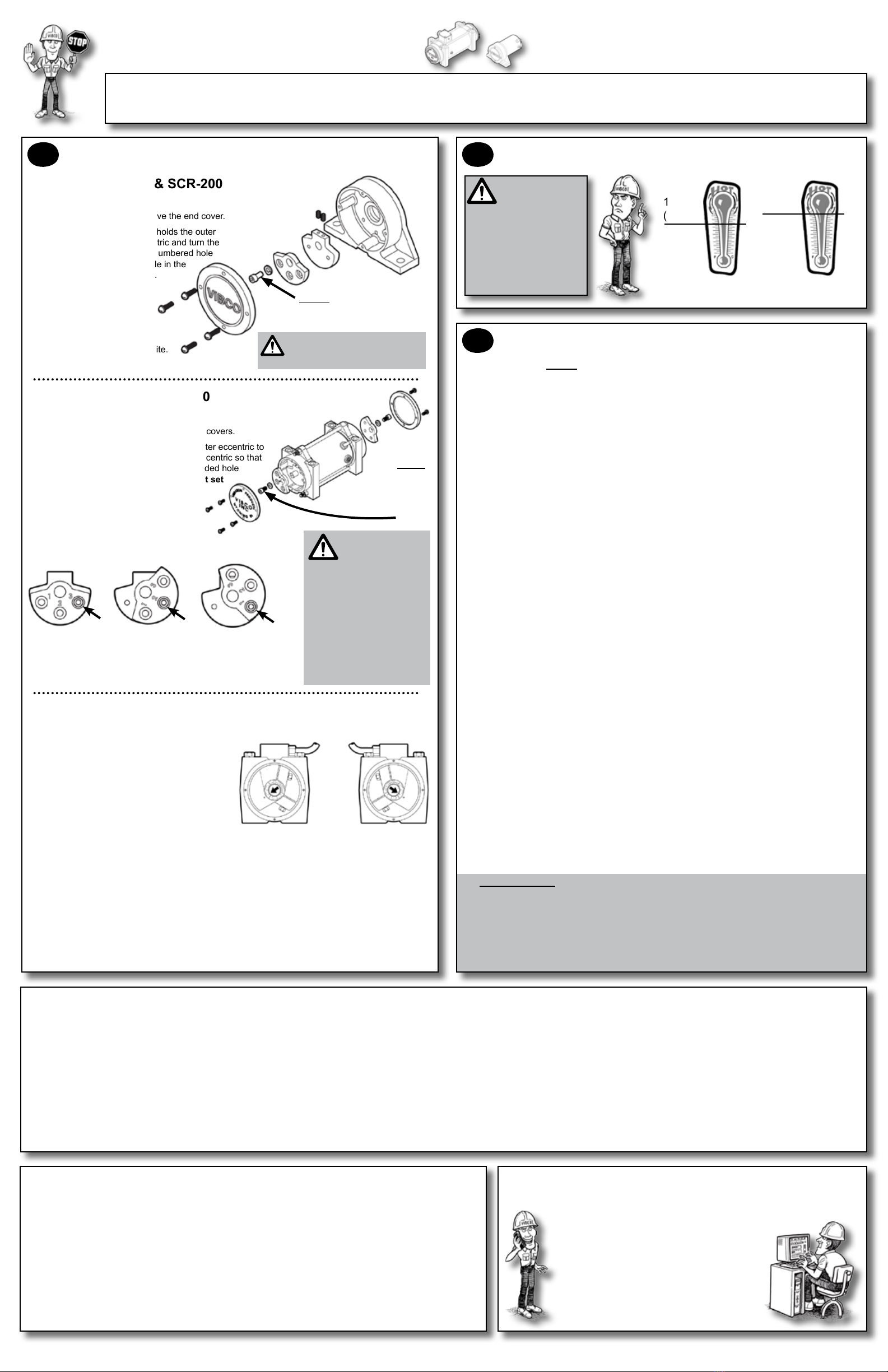
MODELS: SCR-100 & SCR-200
To change the force:
Disconnect power and remove the end cover.1)
Remove the cap screw that holds the outer2)
eccentric to the inner eccentric and turn the
outer eccentric so that the numbered hole
aligns with the threaded hole in the
inner eccentric (see below).
Apply Loctite 242 (or3)
equivalent). Replace the
cap screw.
Replace end cover. End4)
cover bolts have a locking
patch and do not need Loctite.
NOTE: Remove cap screw &
adjust as shown below. Then
replace the bolt & cover.
NOTE: Models SCR-50, 60 &
SCRW-400 have xed eccentrics
and are NOT eld adjustable.
MODELS: SCR-300, 400, 500
To change the force:
Disconnect power and remove both end covers.1)
Remove the cap screw that holds the outer eccentric to2)
the inner eccentric and turn the outer eccentric so that
the numbered hole aligns with the threaded hole
in the inner eccentric. NOTE: You must set
both ends of the vibrator to the same
setting.
Apply Loctite 242 (or equivalent).3)
Replace the cap screw.
Replace both end covers. End cover bolts have a locking4)
patch and do not need Loctite.
NOTE:
Remove cap
screw & adjust as
shown below. Then
replace the bolt &
cover.
MODEL: SCR-1000
MODEL SCR-1000 to change the force:
Disconnect power and remove both end covers1.
from vibrator.
Loosen the bolt that holds the outer, labeled2.
eccentric to the shaft. NOTE: some models
have only one eccentric per side.
Turn the eccentric on the shaft to adjust force3.
output. Align the arrow on the shaft to the
desired setting. The higher the number, the
greater the force.
Settings 1 - 3 are continuous duty rated
Settings 4 - 6 are intermittent duty rated only
NOTE: You must set both ends of the vibrator to the same setting.
4. Tighten eccentric bolts and reinstall end covers.
For vibrators mounted in tandem (side to side, not end-to-end) to produce linear motion
on tables & feeders:
To produce linear motion you must make sure vibrators rotate opposite from one another. Force
output labels should be opposite to one another when viewed from the same side (one increases
clockwise, the other counter-clockwise as in picture above). Follow instructions as above, & be sure
you set both vibrators & both ends to the same setting. Consult VIBCO for more details.
LEFT RIGHT
MY MATERIAL STILL ISN’T MOVING!
1. Did you put your vibrator in the right location? Did you mount your vibrator properly?
2. Do you have the right vibrator for the job? Does it provide enough force? Is it the right
frequency? Is it set to the maximum force? See eccentric setting info to left. Still not
sure? Call VIBCO Technical Support at 800-633-0032.
THE VIBRATOR WON’T START!
1. Check for blown fuses in vibrator. Replace with time-delayed 250V type.
NOTE: For SCR Models 50, 60, 100, 200, 300 & 400 fuse is located INSIDE control
box. For SCR Models 500 & 1000, fuse is located on lid of control box in holder marked
FUSE.
2. Check power supply to unit. Are you getting the proper voltage? NOTE: Remember that
SCR units are built with a 90VDC motor powered by 115VAC power, converted at
the speed control box.
3. Check eld continuity, if “open” eld winding is burned or has a short, replace eld. If
unsure how to check continuity, call VIBCO or consult a licensed electrician.
4. Check control potentiometer. If shorted, replace.
5. Check vibrator brushes for wear. Each unit has two brushes. Refer to full detail manual
at www.vibco.com for correct brush lengths. Replace if worn below minimum length.
VIBRATOR STOPS RUNNING!
1. Check for blown fuses in vibrator. Replace with time-delayed 250V type.
NOTE: For SCR Models 50, 60, 100, 200, 300 & 400 fuse is located INSIDE control
box. For SCR Models 500 & 1000, fuse is located on lid of control box in holder marked
FUSE.
2. Check power supply to unit.
3. Check vibrator brushes for wear. Each unit has two brushes. Refer to full detail
manual at www.vibco.com for correct brush lengths. Replace if worn below minimum
length.
4. Are you running the vibrator in a wet or washdown environment? Consult VIBCO about
washdown rated models.
5. Are you running the vibrator in a high temperature environment? Consult VIBCO about
high temp rated models. Refer to full detail instructions for proper mounting in high
temp applications.
6. Are you running the vibrator continuously? All VIBCO heavy duty models are rated for
continuous duty but only at certain eccentric settings. See diagrams to left for proper
output force settings for continuous duty.
NOTE: For best performance and vibrator life cycle, it is best to run them intermittently.
Consult VIBCO for available timers.
7. Are you repeatedly stopping and starting the vibrator? This can overload the vibrator.
Use the following guidelines for proper timing of starts and stops:
DUTY CYCLE
All SCR Models are rated for CONTINUOUS DUTY at frequency settings between 950 -
2500 vibrations per minute (VPM) -- which is approx. 25 to 60 on speed control dial.
For frequencies below 950 or above 2500 VPM, rating is INTERMITTENT DUTY. Use
50% duty cycle where maximum run time = 30 minutes in any one hour period.
NOTE: Duty cycle can be increased by adding additional ventilation. Consult VIBCO
for details.


