manuals.online logo
Brands
  1. Home
  2. •
  3. Brands
  4. •
  5. Powerohm Resistors
  6. •
  7. Control Unit
  8. •
  9. Powerohm Resistors BM Series User manual

Powerohm Resistors BM Series User manual

IMPORTANT: These instructions should be read thoroughly before installation. All warnings and
precautions should be observed for both personal safety and for proper equipment performance
and longevity. Failure to follow these instructions could result in equipment failure and/or serious
injury to personnel. Braking modules contain lethal voltages when connected to the inverter. It is
very important to remove power to the inverter before installing or servicing this unit. Always
allow adequate time (approximately 5 minutes) after removing power before touching any
components. The LED’s must be completely out before servicing the unit.
Powerohm Instruction Manual
For BM “BG” Series
Braking Modules
2 a brand of ICD, Inc.
• Page 2: Table of Contents for installation manual HCPMAN0001_R3 (2018-03-05)
• Page 3: Table of Contents (cont.)
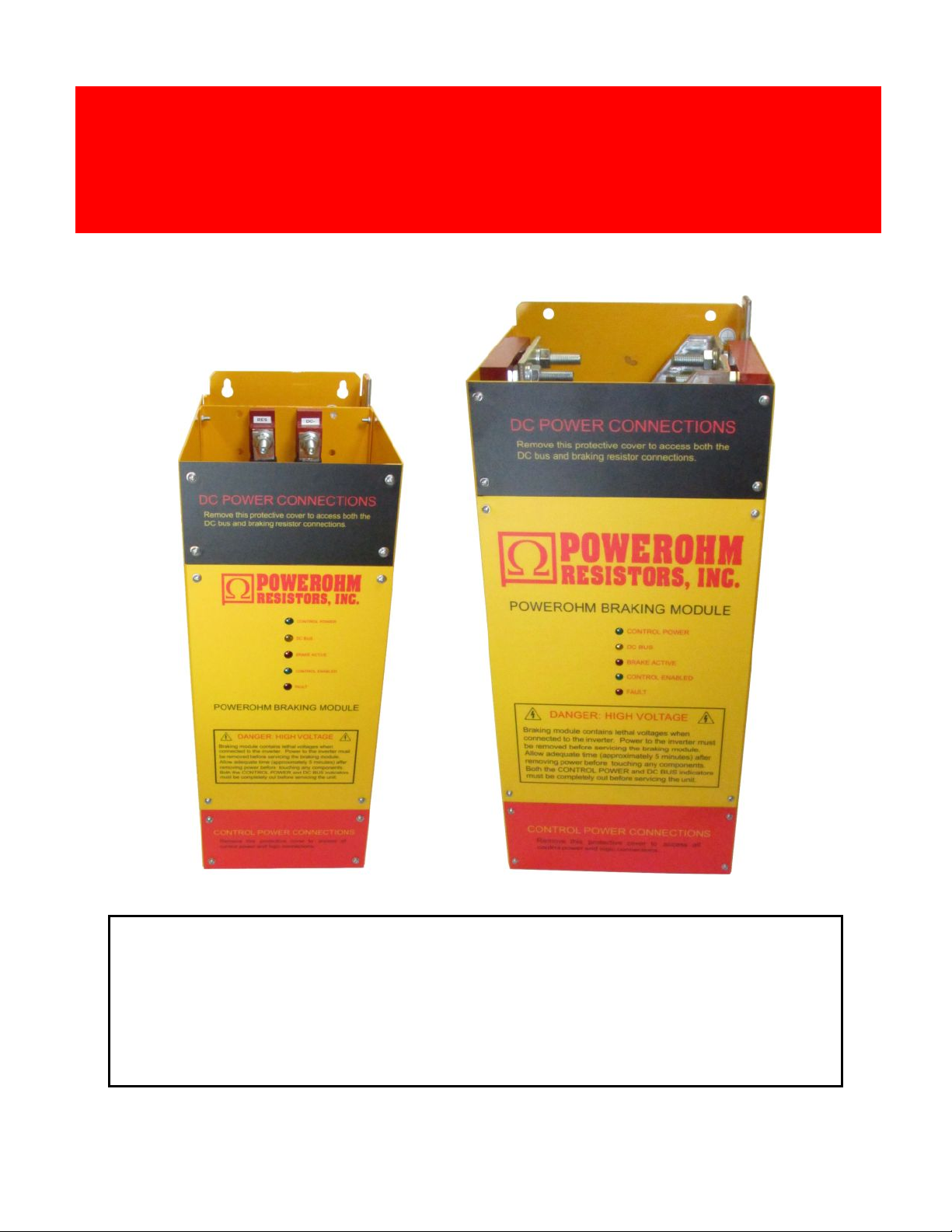
• Page 4: Product Overview
• Page 5: Inspection & Environmental Conditions
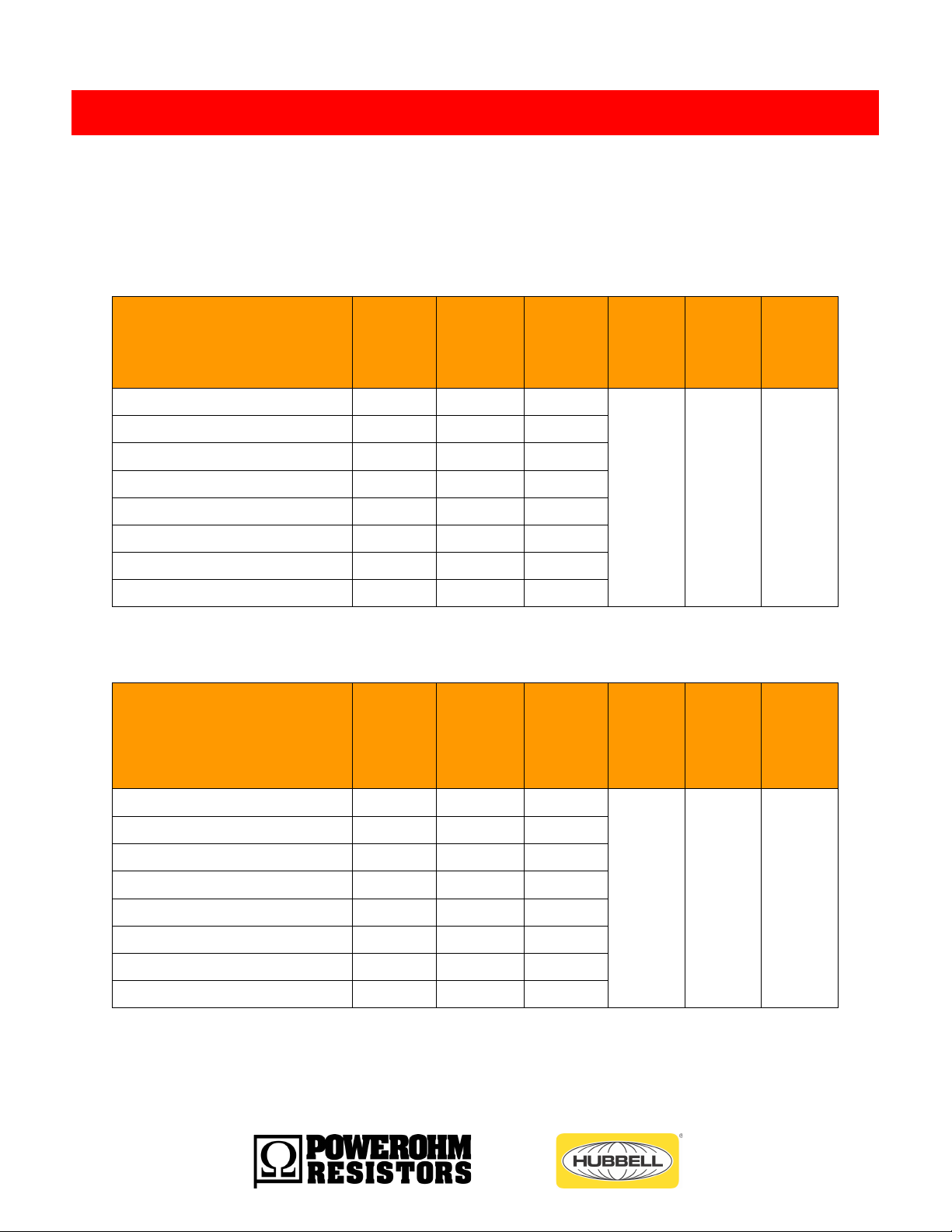
• Page 6: Electrical Ratings for 450 & 600 amp Models
• Page 7: Electrical Ratings for 900 & 1200 amp Models
• Page 8: Equipment Installation
• Page 9: Mounting Orientation
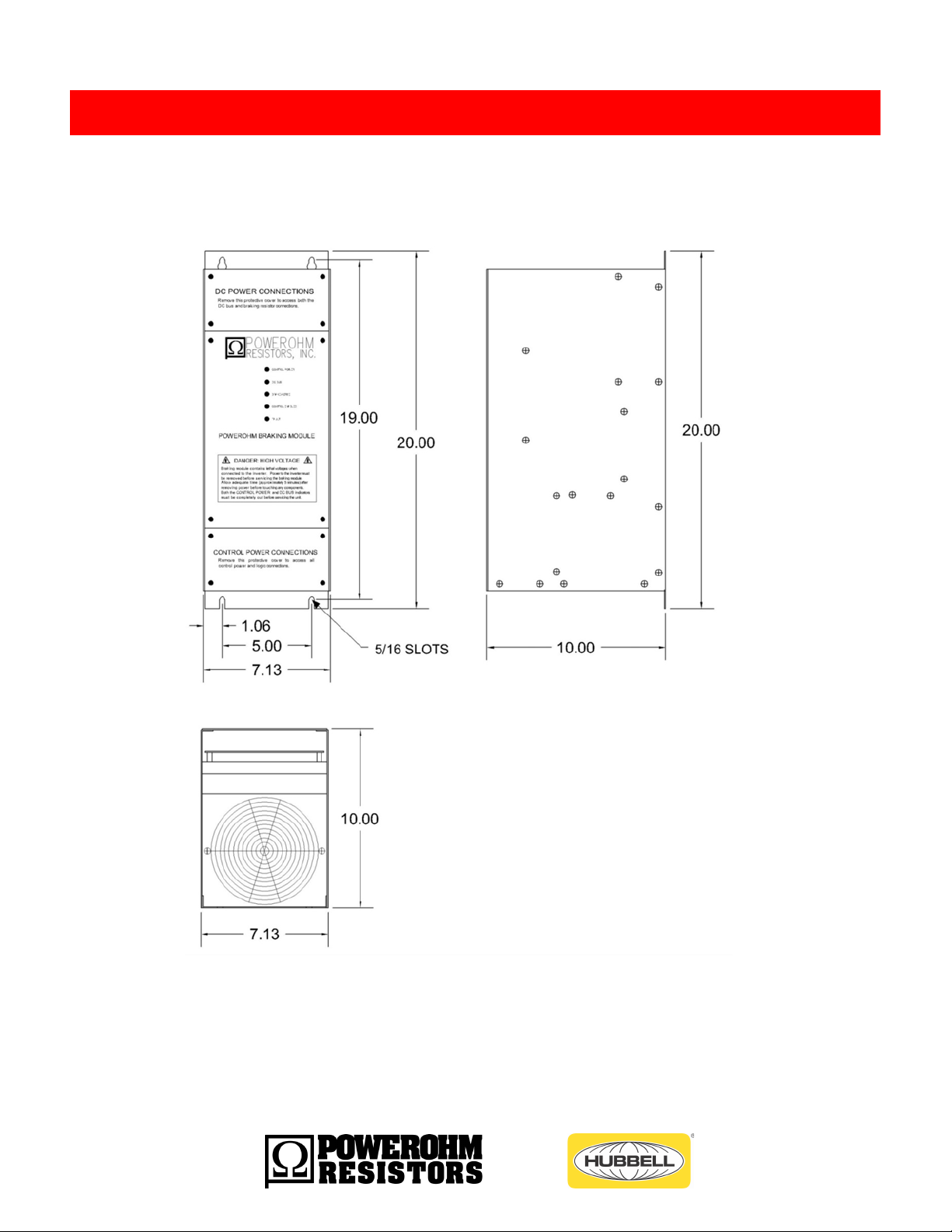
• Page 10: Dimensions and Weight for 450 & 600 amp Models
• Page 11: Dimensions and Weight for 900 & 1200 amp Models
• Page 12: Wiring Recommendations
• Page 13: Wire Sizing
• Page 14: Power Connections for 450 & 600 amp models
• Page 15: Power Connections for 900 & 1200 amp models
• Page 16: TB3 115vac Enable & Control Connection Specs
• Page 17: TB3 24vdc Enable & Control Connection Specs
• Page 18: TB2 I/O Input Command Connections Specs
• Page 19: TB2 I/O Input Commands Basic Schematic
• Page 20: TB2 I/O Input Commands Detailed Descriptions
• Page 21: TB1 I/O Output Status Signal Connection Specs
• Page 22: TB1 I/O Output Status Basic Schematic
• Page 23: TB1 I/O Output Status Detailed Descriptions
• Page 24: TB1 I/O Output Status Detailed Descriptions
• Page 25: Master / Slave Fiber Optic Connections
• Page 26: Module Set Up
• Page 27: System Integration - Drive DC Bus Connections
• Page 28: System Integration – Power Connections for single Module
• Page 29: System Integration – Power Connections for 2 Modules
• Page 30: System Integration – Power Connections for 3 or more Modules
• Page 31: System Integration – Control Connections for 2 Module
• Page 32: System Integration – Control Connections for 3 or more Modules
Table of Contents
3 a brand of ICD, Inc.
• Page 33: Communications Channel Assignments
• Page 34: Communications Module Location
• Page 35: Communications Module ProfiBus Addressing
• Page 36: Communications Module ProfiBus Cables
• Page 37: Brake Module Start Up
• Page 38: Brake Module Start Up
• Page 39: Communications Ethernet Module Start Up
• Page 40: Communications Ethernet Module Troubleshooting
• Page 41: Communications ProfiBus Module Start Up
• Page 42: Communications ProfiBus Module Troubleshooting
• Page 43: Maintenance
• Page 44: Brake Module Troubleshooting LEDs
• Page 45: Brake Module Troubleshooting
• Page 46: Brake Module Troubleshooting
• Page 47: Brake Module Troubleshooting
• Page 48: Back Page
4 a brand of ICD, Inc.
AC variable frequency drives are commonly used with general purpose AC induction motors to
form reliable variable speed drive systems. Problems with these drive systems can occur when an
application requires a deceleration rate faster than what can be managed by the drive alone, or
when motor speeds exceed the synchronous speed set by the output frequency of the drive (which
is called an overhauling load condition). Both of these conditions create regenerated power which
flows from the motor back into the drive, causing its DC Bus to rise. To manage the regenerated
power and avoid shutting the drive down due to an over-voltage trip, this power must be dissipated
by an external braking resistor.
PowerOhm Type BG Braking Modules can be used in conjunction with any AC drive to monitor
the DC bus of the drive and activate external braking resistor as needed not only to avoid over-
voltage trips, but to greatly improve the performance of the drive system. The use of Braking
Modules and resistors increase the braking torque capability of a variable frequency drive,
allowing faster and more controlled deceleration times.
To accommodate system horsepower requirements beyond the capability of a single Module,
the Modules are all Master/Slave programmable. This allows an arrangement of multiple Modules
to effectively function as a single higher rated module.
The products covered in this manual are intended to be used with Listed inverter drives. The
input of the DBU is only to be connected across the DC bus of an inverter drive. Conductors for
connection of the DBU shall be according to the NFPA 70 (national Electric Code) and the drives
installation instructions.
Product Overview
5 a brand of ICD, Inc.
Upon receipt of your PowerOhm Braking Module, be sure to carefully unpack the module and inspect the unit
carefully for any shipping damage. The module contains electronics that can be damaged by static electricity, so
handle in accordance with industry standards. Check for loose, broken or otherwise damaged parts due to
shipping. Report any shipping damage immediately to the freight carrier. Be sure to verify that the part number and
ratings listed on the nameplate match the order specification and the capabilities of the drive system. The ratings
listed on the nameplate are critical – installing and energizing the incorrect part number could damage the
braking module and/or the drive!
The PowerOhm Type BG Braking Module should be installed in an environment protected from moisture and
excessive dust. Dust buildup can reduce the electrical insulation characteristics of the unit and moisture can cause
arching or shorting. Air must be free of combustible gases and corrosive vapors.
Chassis classification: Open Type
Ambient Temperature Range: -10ºC to 40ºC
Maximum Altitude: 3300 feet (1000m)
Maximum Vibration: 10 to 20Hz, 32ft/sec/sec; 20 to 50Hz, 6.5 ft/sec/sec
Inspection upon Receipt
Environmental Conditions
6 a brand of ICD, Inc.
The PowerOhm Type BG Braking Module is available in line voltages ranging from 208 to 720 volts. Peak
currents up to the maximum are allowed at intermittent duty cycles (reference the below tables for details).
Options are designated in the part number after the dash at the end. -24v = 24vdc control power.
-AEN = Acromag Ethernet communications module. -APB = Acromag PROFIBUS communications module.
TABLE 1a: General Specifications for 450 amp Type BG Braking Modules
PowerOhm
Part No.
Nominal
AC Line
Voltage
Minimum
Ohms
@ listed
Turn ON
Turn ON
Voltage
RMS
Cont
Current
Max
Peak
Current
Max
Watt
Loss
HCPBM208450-(24,AEN,APB)
208
.56
336
450
600
1155
HCPBM240450-(24,AEN,APB)
240
.65
390
HCPBM380450-(24,AEN,APB)
380
1.02
612
HCPBM415450-(24,AEN,APB)
415
1.12
670
HCPBM480450-(24,AEN,APB)
480
1.29
775
HCPBM600450-(24,AEN,APB)
600
1.62
970
HCPBM690450-(24,AEN,APB)
690
1.82
1090
HCPBM720450-(24,AEN,APB)
720
1.87
1120
TABLE 1b: General Specifications for 600 amp Type BG Braking Modules
PowerOhm
Part No.
Nominal
AC Line
Voltage
Minimum
Ohms
@ listed
Turn ON
Turn ON
Voltage
RMS
Cont
Current
Max
Peak
Current
Max
Watt
Loss
HCPBM208600-(24,AEN,APB)
208
.37
336
600
900
1522
HCPBM240600-(24,AEN,APB)
240
.43
390
HCPBM380600-(24,AEN,APB)
380
.68
612
HCPBM415600-(24,AEN,APB)
415
.74
670
HCPBM480600-(24,AEN,APB)
480
.86
775
HCPBM600600-(24,AEN,APB)
600
1.08
970
HCPBM690600-(24,AEN,APB)
690
1.21
1090
HCPBM720600-(24,AEN,APB)
720
1.24
1120
Electrical Ratings
7 a brand of ICD, Inc.
TABLE 1c: General Specifications for 900 amp Type BG Braking Modules
PowerOhm
Part No.
Nominal
AC Line
Voltage
Minimum
Ohms
@ listed
Turn ON
Turn ON
Voltage
RMS
Cont
Current
Max
Peak
Current
Max
Watt
Loss
HCPBM208900-(24,AEN,APB)
208
.25
336
900
1350
2257
HCPBM240900-(24,AEN,APB)
240
.29
390
HCPBM380900-(24,AEN,APB)
380
.45
612
HCPBM415900-(24,AEN,APB)
415
.5
670
HCPBM480900-(24,AEN,APB)
480
.57
775
HCPBM600900-(24,AEN,APB)
600
.72
970
HCPBM690900-(24,AEN,APB)
690
.81
1090
HCPBM720900-(24,AEN,APB)
720
.83
1120
TABLE 1d: General Specifications for 1200 amp Type BG Braking Modules
PowerOhm
Part No.
Nominal
AC Line
Voltage
Minimum
Ohms
@ listed
Turn ON
Turn ON
Voltage
RMS
Cont
Current
Max
Peak
Current
Max
Watt
Loss
HCPBM2081200-(24,AEN,APB)
208
.19
336
1200
1800
2992
HCPBM2401200-(24,AEN,APB)
240
.22
390
HCPBM3801200-(24,AEN,APB)
380
.34
612
HCPBM4151200-(24,AEN,APB)
415
.37
670
HCPBM4801200-(24,AEN,APB)
480
.43
775
HCPBM6001200-(24,AEN,APB)
600
.54
970
HCPBM6901200-(24,AEN,APB)
690
.61
1090
HCPBM7201200-(24,AEN,APB)
720
.62
1120
8 a brand of ICD, Inc.
The PowerOhm Type BG Braking Module should be installed on a low vibration surface that is non-flammable.
Attention: Installation and removal of this equipment should be done by qualified
personnel only. Equipment must be installed in accordance with all applicable
national and local electrical codes and regulations.
MOUNTING REQUIREMENTS
To allow proper cooling, it is very important to install the fan cooled PowerOhm braking modules in a location
with an ambient temperature not exceeding 40 degrees Celsius or below 0 degrees Celsius.Modules should
be installed in an environment with sufficient circulation of clean, dry air. The module should be installed in an
area allowing a minimum of 6 inches of free space above and below the frame, and 2” on both sides to allow
proper airflow and cooling.
POWER EARTH GROUNDING
A good earth ground is essential in today’s PWM drive installations. The PowerOhm brake module should have
a dedicated Power Earth ground wire that runs directly to the drive PE ground to mitigate drive system noise.
Each drive and cabinet should be properly earth grounded, with all safety grounds connected directly to PE
ground. Excessive common mode noise may need to be shunted to PE ground.
CONTROL EARTH GROUNDING
In order to minimize the effects of drive system noise it is recommended that the control power supply and I/O
INPUTS not be tied to earth ground. If they must be tied to earth for other system components, use a clean
earth ground.
Equipment Installation
9 a brand of ICD, Inc.
The PowerOhm BG Series Braking Module must be installed in a vertical position in order to meet published
current ratings. (see Figure 1).
FIGURE 1: Mounting Orientation for BM Braking Modules
Mounting Orientation
10 a brand of ICD, Inc.
FIGURE 2a: Braking Module Dimensions for 450 & 600 amp Models
Weight: The weight of the 450 amp unit is 30lbs and the 600 amp is 34 lbs.
Dimensions and Weight
11 a brand of ICD, Inc.
FIGURE 2b: Braking Module Dimensions for 900 & 1200 amp Models
Weight: The weight of the 900 amp unit is 55lbs and the 1200amp is 60lbs.
12 a brand of ICD, Inc.
It is recommended that the AC drive manual, braking resistor instructions and any other pertinent
documentation be thoroughly reviewed before proceeding.
NEVER bundle power wires and control wires together. Control and power wiring should be separated to avoid
electrical noise and interference problems. The responsibility for proper wiring lies with the machine builder.
The wiring between the drive and braking module should not exceed 15 feet and between the braking resistor
and braking module should not exceed 150 feet.
Use CU conductors only with insulation rated for 75° C minimum or equivalent.
Important: Always properly ground each component to Power Earth ground (PE). Ground Brake Module
DIRECTLY to AC Drive Module Power ground, and ensure the drive cabinet has a good ground.
Figure 3: Power Wiring Lengths Between Drive System Components
WARNING: Never install a braking resistor directly across the DC bus of the drive.
Drive damage or failure may occur upon applied power. Additionally, without the
braking module to activate and deactivate the braking resistor, the resistor will
dissipate power continuously and be subject to overheating and failure.
Wiring Recomendations
13 a brand of ICD, Inc.
The National Electric Code (NEC) and local regulations govern the installation and wiring of electrical
equipment such as variable frequency drives, braking resistors and braking modules. DC power wiring, AC power
wiring, control wiring and conduit must be installed in accordance with all applicable codes and regulations.
Reference Table 2 for suggested minimum wire sizes only. Keep in mind the duty cycle rating greatly affects the
minimum wire size needed.
TABLE 2: Wire Sizing for Power Interconnections
MOTOR HP @ 10% DUTY CYCLE
MIN
WIRE
SIZE
240VAC
480VAC
600VAC
50HP-100HP
100HP to 200HP
100HP to 200HP
4awg
100HP to 200HP
300HP to 500HP
300HP to 500HP
1/0
N/A
500HP-1000HP
500HP-1000HP
4/0
MOTOR HP @ 30% DUTY CYCLE
MIN
WIRE
SIZE
240VAC
480VAC
600VAC
50HP-100HP
100HP to 200HP
100HP to 200HP
2awg
100HP to 200HP
300HP to 500HP
300HP to 500HP
2/0
N/A
500HP-1000HP
500HP-1000HP
350kcm
Note: 18 AWG wire is sufficient for all control and signal wiring
ATTENTION: The National Electric Code (NEC) and local regulations govern the
installation and wiring of electrical equipment such as braking resistors and
modules. DC power wiring, AC power wiring, control wiring and conduit must be
installed in accordance with all applicable codes and regulations.
Wire Sizing
14 a brand of ICD, Inc.
POWER CONNECTIONS
• The PowerOhm Type BG Braking Module features a total of five power connections.
• Field wiring to studs must be made by a UL listed clamp or closed terminal connector
• sized for the wire gauge involved
• Run both resistor leads direct to the RES+ and RES – terminals.
• Run both DC bus leads from drive direct to the DC+ and DC – terminals.
• Keep away from all control wiring and cross at 90deg angles at least an inch away.
TABLE 3a: Descriptions of Power Connections for 450 & 600 amp
Terminal
Designation
Terminal Description
Connection
Type
Socket
Size
Max.
Torque
(lb-ft)
DC -
DC Bus Connection (Negative)
3/8” studs
9/16”
20
DC+
DC Bus Connection (Positive)
3/8” studs
9/16”
20
Ground Connection
3/8” hole
-
-
RES -
Braking Resistor IGBT Connection
3/8” studs
9/16”
20
RES+
Braking Resistor DC+ Connection
3/8” studs
9/16”
20
450amp 600 amp
Power Connections
Power
Earth
Ground
15 a brand of ICD, Inc.
TABLE 3b: Descriptions of Power Connections for 900 & 1200 amp
Terminal
Designation
Terminal Description
Connection
Type
Socket
Size
Max
Torque
(lb-ft)
DC -
DC Bus Connection (Negative)
Two ½” studs
¾”
50
DC+
DC Bus Connection (Positive)
Two ½” studs
¾”
50
Ground Connection
3/8” hole
-
-
RES -
Braking Resistor IGBT Connection
Two ½” studs
¾”
50
RES+
Braking Resistor DC+ Connection
Two ½” studs
¾”
50
900 & 1200 amp
Power
Earth
Ground
16 a brand of ICD, Inc.
TABLE 4a: Standard 115vac Control Power
TB3 Terminal
Number
Terminal Description (TB3)
Electrical
Ratings
Max Wire
Size
Maximum
Torque (lb-in)
1
115vac (Non Polarized)
115vac / 1a
14awg
2.2
2
115vac (Non Polarized)
*18AWG is sufficient for control wiring
While it is safe to earth ground the external control supply neutral, the placement of this ground could
inadvertently add to system noise in the control loop. Floating this source may be best for noise immunity.
115vac CONTROL POWER DESCRIPTIONS (TB3)
1. 115vac +/- 10% is used for control and fan power.
a. Supply valid fault occurs when the internal 24v feeding the control board drops below 19vdc.
b. Current draw is approximately .5 amps, with a surge up to 1 amp at power up.
Control Power Connections
17 a brand of ICD, Inc.
TABLE 4b: Special 24vdc Control Power (- 24 option)
TB3
Terminal
Number
Terminal Description (TB3)
Electrical
Ratings
Max Wire
Size
Maximum
Torque (lb-in)
1 (+)
24vdc Input Power Pos
24vdc / 3a
14awg
2.2
2 (-)
24vdc Input Power Neg
*18AWG is sufficient for control wiring
While it is safe to earth ground the external control supply, the placement of this ground could inadvertently add
to system noise in the control loop. Floating this source may be best for noise immunity.
24vdc CONTROL POWER DESCRIPTION (TB3)
1. 24Vdc is used for control and fan power.
a. To achieve full current rating of Brake Module this supply must be at least 24vdc for cooling
b. Supply valid fault occurs when the 24v feeding the control board drops below 20vdc
c. Current draw is approximately 1.5 amps, with a surge up to 3 amps at power up
18 a brand of ICD, Inc.
TABLE 5: TB2 Input Control Command Descriptions
TB2 Terminal
Number
Terminal Description (TB2)
Electrical
Ratings
Max Wire
Size
Maximum
Torque (lb-
in)
1 (+)
Enable
10ma
24vdc
14awg*
2.2
2 (-)
Common
3 (+)
Master or Slave Select
4 (-)
Common
5 (+)
IOC/ IOV, IUV Reset
6 (-)
Common
7 (+)
DC Bus Discharge
8 (-)
Common
9 (+)
M/S Signal +IN/ OUT
10 (+)
M/S Signal +IN/ OUT
11 (-)
M/S Signal Common
12 (-)
M/S Signal Common
*18AWG is sufficient for control wiring
While it is safe to earth ground the control input commons, the placement of this ground could inadvertently add
to noise in the system control loop. Floating these commons may be best for noise immunity.
Control Input Connections
19 a brand of ICD, Inc.
FIG 4: TB2 Input Command Details
I/O INPUT COMMAND DESCRIPTIONS (TB2)
1. ENABLE
a. Short TB2, 1 & 2 to enable brake module
b. Allows the brake module to output pulses to IGBT switch
c. Front panel “Control Enabled” LED ON indicates the presence of an enable contact closure
2. M/S SEL
a. Short TB2, 3 & 4 to run single module or to set as Master
b. Steers pulses to external slaves.
Control Input Connections
20 a brand of ICD, Inc.
3. RESET
a. Short TB2, 5 & 6 to reset
b. For best noise immunity keep closed, and then momentarily cycle to reset
c. Clears any temporary faults
d. Will not clear IGBT short or over-temp faults if they still exist
4. DCHARG
a. Short TB2, 7 & 8 to turn on brake and discharge drive or system DC bus
b. Functions only in master mode
c. Dumps DC bus caps into braking load resistor
d. Use during maintenance to save time waiting for safe discharge levels
1. MASTER SIGNAL (OUTPUT)
a. Connect Slave module signal wires to TB2, 10(+) & 12(-) of the master module
e. Outputs signal when master is selected by shorting TB2. 3 & 4
b. Fiber optic connection for multiple slave systems
2. SLAVE SIGNAL (INPUT)
a. Connect Master module output signal to TB2, 9(+) & 11(-) of the slave module
b. Accepts external signal when M/S select at TB2. 3 & 4 is NOT shorted
c. Fiber optic option available when using more than one slave

This manual suits for next models

129

Popular Control Unit manuals by other brands

Nova SWISS NV Series General operating instructions

Nova

Nova SWISS NV Series General operating instructions

Congatec COM Express conga-TCA5 user guide

Congatec

Congatec COM Express conga-TCA5 user guide

Toshiba 2000 V Series manual

Toshiba

Toshiba 2000 V Series manual

RTimes RTSS-X501M user manual

RTimes

RTimes RTSS-X501M user manual

oventrop Regudis W Installation and operating instructions

oventrop

oventrop Regudis W Installation and operating instructions

Love Controls 16A2 Series instructions

Love Controls

Love Controls 16A2 Series instructions

Paradyne iMarc SLV9128 installation instructions

Paradyne

Paradyne iMarc SLV9128 installation instructions

Emerson Alco Controls TCLE Operating	 instruction

Emerson

Emerson Alco Controls TCLE Operating instruction

ADLINK Technology MPC-8164 user manual

ADLINK Technology

ADLINK Technology MPC-8164 user manual

Pickering PXI 40-145 user manual

Pickering

Pickering PXI 40-145 user manual

Fisher V260 instruction manual

Fisher

Fisher V260 instruction manual

Siemens MJ-4 Series installation manual

Siemens

Siemens MJ-4 Series installation manual

Avalue Technology ESM-EHLC user manual

Avalue Technology

Avalue Technology ESM-EHLC user manual

ADTRAN E1 installation instructions

ADTRAN

ADTRAN E1 installation instructions

APV SAPM manual

APV

APV SAPM manual

DNS LK-400 Operation manual

DNS

DNS LK-400 Operation manual

Omnivision CameraChip OV9650 Implementation guide

Omnivision

Omnivision CameraChip OV9650 Implementation guide

National Instruments PXIe-6595 Getting started guide

National Instruments

National Instruments PXIe-6595 Getting started guide

manuals.online logo
manuals.online logoBrands
  • About & Mission
  • Contact us
  • Privacy Policy
  • Terms and Conditions

Copyright 2025 Manuals.Online. All Rights Reserved.