manuals.online logo
Brands
  1. Home
  2. •
  3. Brands
  4. •
  5. PowerShield
  6. •
  7. Switch
  8. •
  9. PowerShield PSMBSW10K Guide

PowerShield PSMBSW10K Guide

1. Introduction
The PSMBSW10K is used as an external maintenance bypass switch module to provide
uninterrupted power to the connected loads during UPS scheduled maintenance, battery
replacement and or UPS replacement. It is suited for use with the 6kVA or 10kVA UPS.
Wall-mounting the Unit
Please see the PSMBSW10K physical dimensions below for wall-mount installations.
Unit weight: 6kg
2. Product Overview
3. Installation and Operation
Inspection
Unpack the PSMBSW10K carton and check the contents for the following items:
PSMBSW10K PowerShield Maintenance Bypass Switch module x 1
Quick guide x 1
Gland M25 x 3
Gland M19 x 1
NOTE: Before installation, please inspect the unit and check for damage during
transportation. If there is any evidence of damage, or missing parts, do not apply power to
the unit and immediately notify the carrier and or dealer.
Initial Setup and Connection of the UPS and PSMBSW10K switch module
The Installation and wiring must be performed in accordance with the local electrical
laws/regulations and must be carried out only by qualified and certified personnel.
The cable for 6K/6KL should be rated to carry up to 40A current.
The cable for 10K/10KL should be rated to carry up to 63A current.
1. Connect Utility Input to Utility Input Terminals of PSMBSW10K switch module.
2. Connect UPS input terminals of PSMBSW10K switch module to input terminals of UPS.
3. Connect output terminals of UPS to UPS output terminal of PSMBSW10K switch module.
PowerShield Maintenance Bypass Switch
PSMBSW10K for 6KVA or 10KVA UPS
www.powershield.com.au
UPS input breaker
Maintenance bypass switch
Control output signal connector
Output terminals
Utility input terminals
UPS output terminals
UPS input terminals
Grounding terminal
4. Connect output terminals of PSMBSW10K switch module to load.
5. Connect UPS EMBS terminals to PSMBSW10K EMBS terminals
Connection of UPS and External Maintenance Bypass Switch Module
Refer to the illustration below for wiring connections:
WARNING: It is essential to connect the EMBS (C1, C2) terminals on the UPS to the EMBS (C1, C2) terminals
on the Maintenance Bypass Switch module. Failure to do so will cause damage to the UPS and void the
warranty. Check the UPS model User manual for the Rear Panel Terminal Block Pin assignment.
4. Operation
Transfer to Maintenance Bypass
To transfer from UPS mode to maintenance “Bypass”, follow the steps below:
Step 1:
To transfer the UPS to static bypass mode automatically, unscrew the two fasteners and
remove the maintenance switch front cover plate above the switch. This will automatically
release the micro switch located behind the maintenance cover plate (and will connect C1 to
C2 on the normally opened micro switch contacts across the EMBS terminals).
Important: Verify the UPS has switched to static bypass mode on the LCD located on the
front panel of the UPS. If this does not happen then do NOT proceed any further.
NOTE: EMBS terminals on module must be correctly connected to EMBS terminals on UPS.
Step 2:
1) For Bypass and Test mode - rotate switch to “BYPASS” position. In this position the UPS
will still receive mains power however the load will be fed from the mains. Testing can
now be performed on the UPS.
2) For Bypass and Isolate mode - switch off PSMBSW10K input breaker on the module. In
this position the UPS will receive no power whatsoever and the load will be supplied from
mains. After confirming there is no voltage present on the terminals the UPS can be
safely removed from the circuit.
All load devices will now be powered directly by the utility and not through the UPS. After
disconnecting the batteries from the UPS, the service and maintenance of the equipment may
commence.
Transfer back to UPS mode
To transfer from maintenance “Bypass” to UPS mode, follow the steps below:
Important: Ensure PSMBSW10K maintenance switch front cover plate is off.
Step 1: Reconnect Battery system and switch UPS input breaker and switch on the
PSMBSW10K input breaker. The UPS will then enter static bypass mode.
Important: Verify the UPS has switched on and is in static bypass mode on the LCD located
on the front panel of the UPS. If this does not happen then do NOT proceed any further.
Step 2: Rotate switch to “UPS” position. All load devices will now be powered by the utility
through the UPS operating in static bypass mode.
Step 3: Replace and secure the PSMBSW10K maintenance switch cover plate.
Step 4: Press “ON” button located on the front panel of the UPS unit. Confirm UPS output is
operating through the inverter on LCD. All the Load devices will now be fully protected by the
UPS.
5. Specification of Critical Components
Parameter
Max.
Input breaker
Current
63 A
Voltage
240 V
Bypass switch
Current
63 A
Voltage
690 V
Input/Output terminal
Current
60 A
Voltage
600 V

Other PowerShield Switch manuals

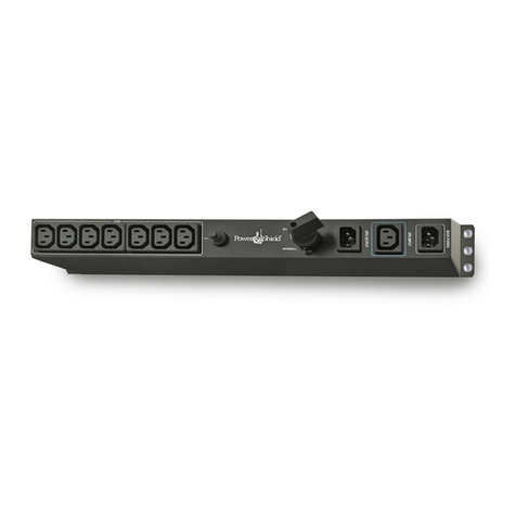
PowerShield PSMBS2K User manual

PowerShield

PowerShield PSMBS2K User manual

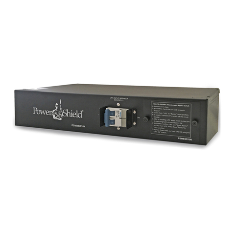
PowerShield PSMBSR10K User manual

PowerShield

PowerShield PSMBSR10K User manual

Popular Switch manuals by other brands

MuxLab 500441 installation guide

MuxLab

MuxLab 500441 installation guide

VPI SE-HD-5-LC user manual

VPI

VPI SE-HD-5-LC user manual

Ruijie RG-S6100 Series Release notes

Ruijie

Ruijie RG-S6100 Series Release notes

Sunricher SR-ZGP2801K4-5C instruction manual

Sunricher

Sunricher SR-ZGP2801K4-5C instruction manual

Gingerway GW-6321 instruction manual

Gingerway

Gingerway GW-6321 instruction manual

Inverto Unicable Multiswitch instructions

Inverto

Inverto Unicable Multiswitch instructions

Eaton TM-1-8240 Series Instruction leaflet

Eaton

Eaton TM-1-8240 Series Instruction leaflet

Juniper EX4200-24T Hardware guide

Juniper

Juniper EX4200-24T Hardware guide

GE BreakMaster Installation and Maintenance

GE

GE BreakMaster Installation and Maintenance

Leonton PT2-0702-SFP Series user manual

Leonton

Leonton PT2-0702-SFP Series user manual

Conrad RSLR2 operating instructions

Conrad

Conrad RSLR2 operating instructions

AMX Endeleo TVM-1600 quick start guide

AMX

AMX Endeleo TVM-1600 quick start guide

D-Link DKVM-IP8 Quick installation guide

D-Link

D-Link DKVM-IP8 Quick installation guide

Allied Telesis AT-x550-18XTQ installation guide

Allied Telesis

Allied Telesis AT-x550-18XTQ installation guide

Buffalo BS-GU2024 user manual

Buffalo

Buffalo BS-GU2024 user manual

MACOM MADR-011022 manual

MACOM

MACOM MADR-011022 manual

Moxa Technologies EtherDevice EDS-30 Hardware installation guide

Moxa Technologies

Moxa Technologies EtherDevice EDS-30 Hardware installation guide

Eads Racal Instruments 1260-45 manual

Eads

Eads Racal Instruments 1260-45 manual

manuals.online logo
manuals.online logoBrands
  • About & Mission
  • Contact us
  • Privacy Policy
  • Terms and Conditions

Copyright 2025 Manuals.Online. All Rights Reserved.