PowerTech PG 60 User manual

PG SERIES
Garagedeur openers
Handleiding

GARAGE DOOR OPENERS USER MANUAL 2
1. Warnings
INHOUD
1. Waarschuwingen
2. Product omschrijving
2.1 toepassingen
2.2 Beschrijving van de automatisering
3. Installatie
3.1 Inventaris van een garagedeuropener
3.2 Rail montage
3.3 Bevestig de rail aan de motor
3.4 Bevestig de rail op de headerwand en het plafond
3.5 Sluit de ontgrendelingssectie aan op de garagedeur
3.6 Laatste stappen voor systeem leren
3.7 Introduction of the emergency release
4. Connection
4.1 Accessories connection
4.2 Door position for start-up phase
4.3 Transmitter memorizing and erasing process
4.4 System learning, reset process, and led display
4.5 Programmable function indication led
4.6 How to set the parameter
4.7 Programmable function setting
5. Function of external accessories
5.1 Function of photocells
5.2 Function of external push button
6. Specification
2
3
3
3
4
4
5
6
6
7
8
8
9
9
9
9
10
10
10
11
12
12
12
12
WARNING :
Please read this instruction manual carefully before theinstallation.
This manual is exclusively for qualified installationpersonnel. Powertech Automation Inc. is not responsible
forimproper installation and failure to comply with localelectrical and building regulations.
Keep all the components of PG Series garage opener system and thismanual for further consultation.
●In this manual, please pay extra attention to the contentsmarked by the symbol:
●Be aware of the hazards that may exist in the proceduresof installation and operation of the garage opener system.
Besides, the installation must be carried out inconformity with local standards and regulations.
●If the system is correctly installed and used following allthe standards and regulations, it will ensure a high degree
of safety.
●Make sure that the door works properly before installingthe garage opener system and confirm the doors are
appropriate for the application.
●Do not let children operate or play with the garage opener system.
●Do not cross the path of the garage opener system whenoperating.
●Please keep all the control devices and any other pulsegenerator away from children to avoid the system being
activated accidentally.
●Do not make any modifications to any components except that it is mentioned in this manual.
●Do not try to manually open or close the doors before yourelease the opener.
●If there is a failure that cannot be solved and is notmentioned in this manual, please contact qualifiedi nstallation
personnel.
●Do not use the garage opener system before all theprocedures and instructions have been carried out and
thoroughly read.
●Install warning signs (if necessary) on the both sides ofthe door to warn the people in the area of potentialhazards.
GARAGE DOOR OPENERS USER MANUAL
3
2. Product description
2.1 Applications
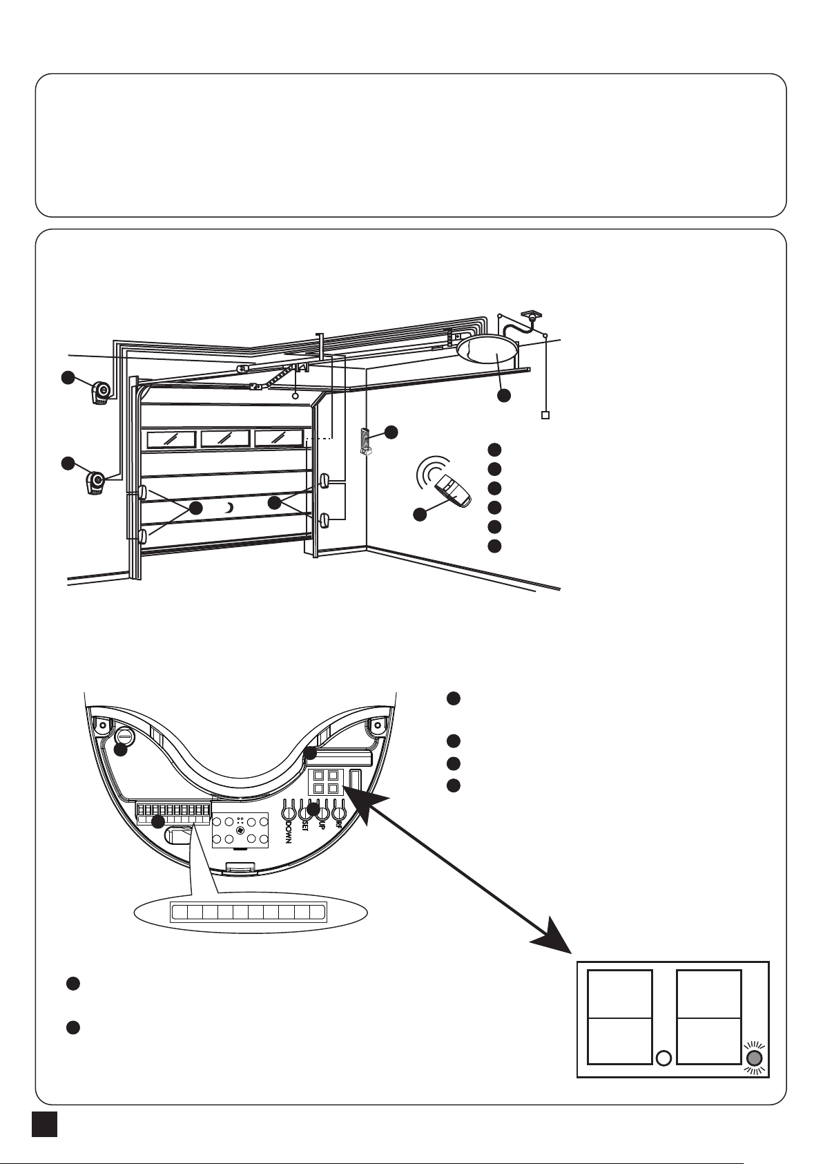
Operation buttons: Remote Function key (RF),
Setting key (Set), UP key (Up), DOWN key (Down).
Connection terminal of Optional accessories
Radio receiver board
Fuse
The power indicator is on the bottom right of the display. When the power
is connected, the LED dot indicator is alight.
When entering to the power-saving mode, the LED power indicator is
flashing ( light for 0.5 second and then no light for 5 seconds )
Garage door opener is applied for residential automation of up and over doors and sectional doors and has to beoperated with
electricity and it’s forbidden to be operated by back-up batteries for normal use. Back-up batteries areonly allowed for emergent
operation when there is a power failure, and the carriage can be released by pulling the cord to move the door manually.
2). The indication of control panel
3). The LED indication
1
1
2
22
3
4
4
5
5
6
6
Garage Door Opener
Photocells (Optional accessories)
External Flashing Light (Optional accessories)
Key selector switch (Optional accessories)
Push Button (Optional accessories)
Transmitter
2.2 Description of the automation
1). The following diagram of typical installation describes some terms and accessories of thedoor automation system:
1
1
2
2
3
4
3
Fuse Receiver
Please set stopper in the open limit position of the rack and after the setup is completed, then garage door opener can
start the system learning process.
1
43
EXT- EXT+ LIT- LIT+ PB GND PH +24V GND +BATT
EXT- EXT+ LIT- LIT+ PB GND PH +24V GND +BATT
2
GARAGE DOOR OPENERS USER MANUAL 4
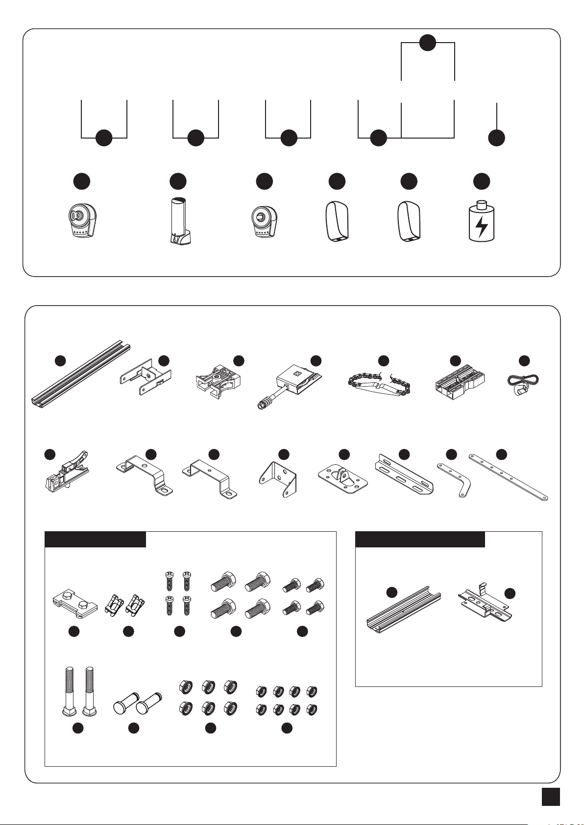
Front hold
bracket
Iron rail x3 Rear pulley
bracket
Front pulley
bracket
Metal Chain Slide block Release Rope
Release trolley
Blocker x1
Motor
hold bracket x2
Ceiling
hold bracket Header bracket Door bracket Ceiling bracket Curved
door arm
Straght
door arm
Junction x2 Ceiling support bracket
3. Installation
3.1 Inventory of a garage door opener
1
13
EXT- EXT+ LIT-
LIT+
PB GND GND +BATT
PH +24V
1
Key Selector Push ButtonFlashing Light TX1 RX1 Battery
1 2
2
3
3
4
4
5
5
6
6
25
108
4
17 18 19 20
21 22 23 24
23
26
6 7
911 12
5
16
14 15
Hardware Inventory Optional for 1pcs x 1M Rail
M8*20
HEX bolt x4
Metric bolt x2
M6*14
HEX bolt x4
M8*8 Nut x6 M6*6 Nut x8
Clevis Pin x2
R-type pin x2 Self-tapping
screws x4

GARAGE DOOR OPENERS USER MANUAL
5
Metal Cham
Slide block
Assemble the front and middle rail with the
junction, and make sure is located at the middle
of the protruding point.
Assemble the back and middle rail with another junction,
and make sure is located at the middle of the
protruding point.
Remove the nut and the spring in the (4) Front pulley bracket. Make sure the metal chain is placed in the gap of the
pulley on the two sides. Insert the (2) Front hold bracket against the rail. Use the spring and the nut to adjust the
tightness of the (5) Metal chain.
3.2 Rail assembly
25
25
6
4
2
4
5
Complete
Complete
Complete
1
2
3
4
8
1. Put the (6) Slide block in the rail track, and put the (5) Metal chain in the rail track.
Make sure the metal mortise part is on right side of the rail.
2. Cross the (5) Metal chain through the (4) front pulley bracket, the (3) rear pulley
bracket, and the (6) Slide block. The metal mortise part should be placed in the
middle of the whole rail.
3. Connect the (5) Metal chain.
5
65
6
18

GARAGE DOOR OPENERS USER MANUAL 6
3.3 Attach the rail to the motor
Ceiling
hold bracket
Ceiling
bracket
Garage
Door
11
11
Header Bracket
Header
Bracket
24
20
HEX bolt
24
Nut
Nut
13
10
CAUTION
1. Connect the insertion gap of the (3) Rear pulley bracket to the output shaft of the motor.
2. Fasten the rail on the motor with (9) motor hold bracket and the Hex nuts (24).
3. Fasten the (10) Ceiling hold bracket and (13) Ceiling bracket at the rear side between the motor and the rear blocker
with Hex bolt (20) and Hex nuts (24)
3.4 Attach the rail on the header wall and ceiling
1. Position (11) Header bracket on the header wall.
*It is recommended that positioned at the center of the garage door.
*The installation height of the (11) Header bracket varies from 30-50cm from the top of the garage door.
2. Install the (11) Header bracket with screws.
3. Attach the front rail to header bracket with bolts.
4. Attach the (13) Ceiling bracket on the crossbeam of ceiling with crews.
Attach Rail to the Header Bracket
1 2 3
Motor
hold bracket
9
Nut24
HEX bolt
20
Rail
Door 2x4 is used to determine
the correct mounting height
from ceiling.
To prevent damage, place the garage door on the top section
to create a temporary support.
GARAGE DOOR OPENERS USER MANUAL
7
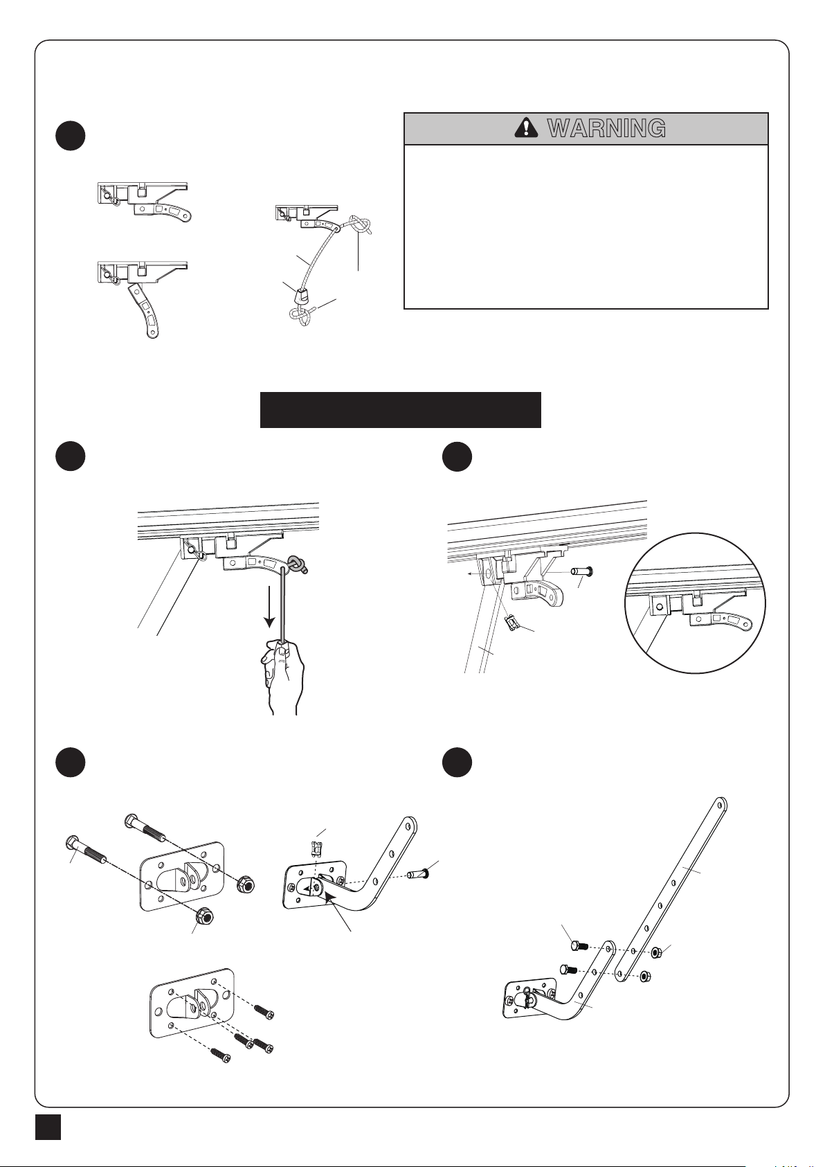
3.5 Connect release section to the garage door
50cm
23
19
21
Nut
Hex Bolt
14
15
Curved
Door Arm
Straight
Door Arm
ENGAGED
Bolt
OR
23
Nut
Secure handle with overhand knot
and heat seal rope.
Pull the (7) Release rope to disengage the
(8) Release trolley
Fasten the (12) Door bracket on the center of the
garage door. Connect (14) Curved door arm to (12)
Door bracket.
Connect (15) Straight door arm to Release trolley
Connect the (7) Release rope on the (8) Release
trolley
Connect (14) Curved door arm and
a straight door arm with bolts and nuts.
RELEASED
3
Pull Down
to Release
Trolley
Overhand
Knot
Rope
7Emergency
Release Handle
1
NOTE: Handle should hang 6 feet (1.5 m) above floor.
Ensure that the rope and handle clear the tops of all
vehicles to avoid entanglement.
To prevent possible SERIOUS INJURY or DEATH from a falling
garage door:
• If possible, use emergency release handle to disengage trolley ONLY
when garage door is CLOSED. Weak or broken springs or
unbalanced door could result in an open door falling rapidly and/or
unexpectedly.
• NEVER use emergency release handle unless garage doorway is
clear of persons and obstructions.
• NEVER use handle to pull door open or closed. If rope knot
becomes untied, you could fall.
WARNING
45
CONNECT DOOR ARM TO TROLLEY
2
15
Straight
Door Arm
22
Clevis Pin
17
R-type pin
17
22
Connect Curved
Door Arm to
Door Bracket
Clevis Pin
R-type pin

GARAGE DOOR OPENERS USER MANUAL 8
3.6 Final steps before system learning
3.7 Introduction of the emergency release
1. Install the blocker the (16) Blocker on the door opened position.
2. Attached the warning sign to the (7) release rope.
3. Connect the power to the motor. Make sure the electric plug and socket are well connected.
2 3
1
1. Pull the (7) Emergency release rope to release the trolley. Make sure the trolley is disengaged. The garage door can be
operated manually.
2. Before restarting the motor, manually move the garage door until the trolley is engaged.
RED
RELEASE
CORO
RED EMERGENCY
RELEASE KNOB
Pull Down
to Release
Trolley
16
To prevent possible SERIOUS INJURY or DEATH from
electrocution or fire:
• Be sure power is not connected to the opener, and
disconnect power to circuit BEFORE removing cover to
establish permanent wiring connection.
• Garage door installation and wiring MUST be in
compliance with all local electrical and building codes.
• NEVER use an extension cord, 2-wire adapter, or
change plug in ANY way to make it fit outlet. Be sure
the opener is grounded.
WARNING
Blocker

GARAGE DOOR OPENERS USER MANUAL
9
4. Connection
4.1 Accessories connection
4.3 Transmitter memorizing and erasing process
Disconnect any
A. Open the cover in order to access the electronic connection terminal of the PG Series garage gate opener.
B. Connect the wires of each accessories on the terminal. (If necessary)
A. Transmitter Memorizing:
Press “RF Learn” button for 3 seconds, and the Display will show “CS”; then press
the transmitterA button within 10 seconds; the“CS” will blink three timesand show
“CS”. After 10 seconds without any movement, “CS” will be off. The transmitter
learning is completed.
B. Erasing Transmitter Memory:
Press and hold "RF Learn" button for 10 seconds, the display will show “CS”. When “CC” show up, the memory is cleared.
C. Memorizing by memorized transmitter:
Press and hold A and B button for 5 seconds, LED light and external flash light will start to blink in the same time. Within 10 seconds,
press any button of the un-memorized transmitter 2 seconds, the transmitter will be memorized after LED light and external flash
light are off. To program by memorized transmitter, just can do the transmitter learning one by one.
Push
Only carry out electrical connections once the electricity supply to the system has been switched off.
4.2 Door position for start-up phase
The manufacturers recommend you unhook the carriage and position the leaf at approximately half travel before starting the
checking and start-up phase of the automation. This will ensure the leaf is free to move both during opening and closure.
Power supply connection
Connect the plug.If necessary, use a commercial adaptor if the plug on the PG Series unit does not correspond to the socket
available.As soon as the system is powerted, you should check the LED in the display. Make sure the LED display is ON.
Never cut or remove the cable supplied with PG Series garage opener. If not already available, the power socket of PG Series
garage opener connection must be fitted by skilled and qualified personnel in strict observance of current legislation, standards and
regulations.
The power supply line must be protected from short circuits and ground leakage.
AB
EXT- EXT+ LIT- LIT+ PB GND PH +24V GND +BATT

GARAGE DOOR OPENERS USER MANUAL 10
4.4 System learning, reset process, and led display
A. System Learning:
Step1: Press and hold “RF” and “SET” buttons 3 seconds, the LED display shows “LE”.
Step2: Press “SET” or “A” button of the transmitter, the motor starts learning process and the display panel shows
“AL”.
Step3: The chain moves to Close Limit with 50% of full speed and connect the trolley. The LED display shows “OL”
and the trolley moves to the Open Limit
which can be decided by the blocker. The LED display shows “CL” and the trolley moves to the Close Limit.
Step4: The motors opens and closes automatically with full speed. The LED display shows “SO” while the system
learning complete. The LED display
show “SF” while the system learning fail.
Note: The over current function and flashing light function will be activated automatically after learning process
complete.
B. Restore Default Setting:
Press “RF” and “DOWN” buttons for 3 seconds, and the LED display shows “CL” to recover the default settings.
C. Motor current auto-detection
The LED display shows the current consumption of the motor
LED Display Programmable Functions LED Display Programmable Functions
4.5 Programmable function indication led
Start transmitter learning mode. Operation testing
Cleaned all studied transmitter. System Learning Fail.
Set up Open Limit. System Learning Completely.
Set up Close Limit. System setting clear
During the system learning procedure, the control panel will automatically detect
the current consumption from each motor, indicate the resistance level of the gate
whiling the motor operation. If this reading increase instantly or stay in high
reading, please check if any object in between of the gate moving area, and
contact your installer for inspection.
4.6 How to set the parameter:
Step 1: Press the“Set” key for 3 seconds, the display will show the function code.
Step 2: Choosing the setting by Up and Down keys, after having chosen the indicated item, press the Set key and
enter the setting of this function. The second digit will be shown on the right of the display, indicating the
related function(please refer below chart for details). Using the Up and the Down Keys to choose the setting
function and press the Set key to save.
GARAGE DOOR OPENERS USER MANUAL
11
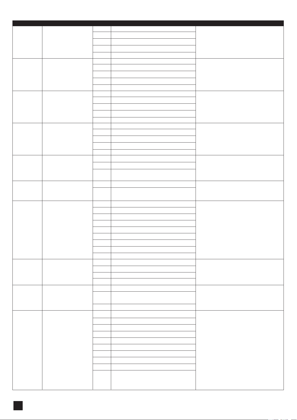
4.7 Programmable function setting
LED Display Definition Function Value Description
Deceleration position starting
point(% full operation)
Open/Stop/Close/Stop
function key
LED light function key
Extra-device function key
Photocell function mode
Warning Buzzer
Auto-close adjustment
LED light function
Over current reaction mode
Over current setting
1
2
3
4
5
6
7
8
9
A
1-1
1-2
1-3
1-4
1-5
2-0
2-1
2-2
2-3
2-4
3-0
3-1
3-2
3-3
3-4
4-0
4-1
4-2
4-3
4-4
5-0
5-1
5-2
6-1
6-2
7-1
7-2
7-3
7-4
7-5
7-6
7-7
7-8
7-9
8-1
8-2
8-3
8-4
9-1
9-2
9-3
1-0
2-0
3-0
4-0
5-0
6-0
7-0
8-0
9-0
9-9
75%
80%
85%
90%
95%
Function off
A Key
B Key
C Key
D Key
Function off
A Key
B Key
C Key
D Key
Function off
A Key
B Key
C Key
D Key
Function off
Stop when photocell is activated
Opening phase: Keep opening when activated
Closing phase: Stop when activated.
Function off
Function on
Function off
30 sec
60 sec
90 sec
120 sec
150 sec
180 sec
210 sec
240 sec
Function off
LED light start running 1 minute
LED light start running 2 minutes
LED light start running 3 minutes
Stop when over current occur
Opening phase: Stop when over current
Closing phase: Reverse 10 cm when over current
Reverse to the end when over current.
Learning current add 0.2A as over current
Learning current add 0.4A as over current
Learning current add 0.5A as over current
Learning current add 0.6A as over current
Learning current add 0.8A as over current
Learning current add 1.0A as over current
Learning current add 1.2A as over current
Learning current add 1.4A as over current
Learning current add 1.6A as over current
Learning current add 1.8A as over current
1.The factory setting is "1-3"
2. The door will reverse 2cm if over current occur in
last 10% distance.
1.The factory setting is "2-1"
1.The factory setting is "3-2"
1.The factory setting is "4-3"
1.The factory setting is "5-0 "
1.The factory setting is "6-1"
2. IF the door left opened for longer than 10mins then buzzer
start beeping and turn off until the door been closed.
1.The factory setting is "7-1"
1.The factory setting is "8-4"
1.The factory setting is "9-2"
1. The factory setting is "3-0"
GARAGE DOOR OPENERS USER MANUAL 12
5. Function of external accessories
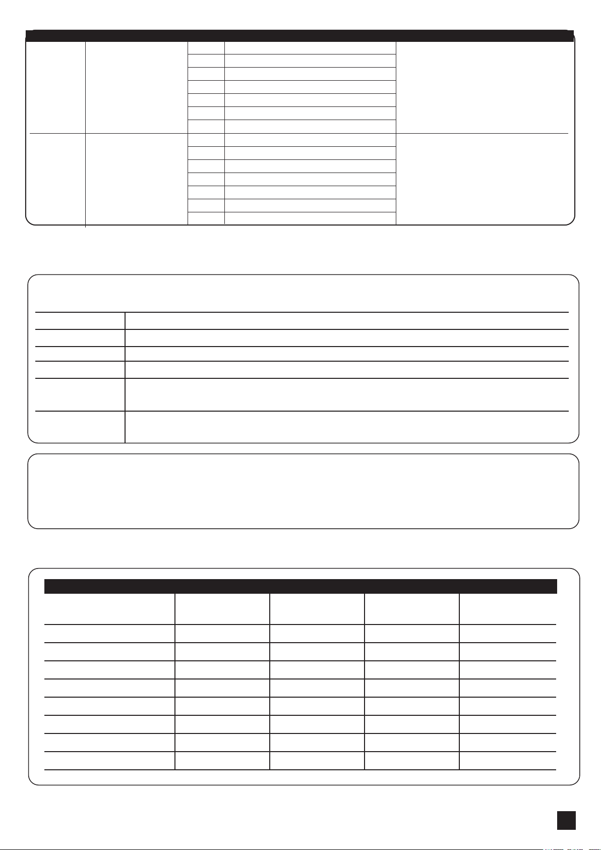
6. Specification
Gate Status
Closed
Opened
Stop during moving
Closing
Opening
The reactions of the photocells when detecting obstacles
No effect. Photocells maintain in the inactive status.
Forbidden to move. If setting the automatic closing function, the door will reload automatic closing time.
Forbidden to move. If setting the automatic closing function, the door will reload automatic closing time.
Stop closing immediately and open. If setting the automatic closing function, the door will reload automatic
closing time.
Stop and wait for a next command. If setting the automatic closing function, the door will reload automatic
closing time.
5.1 Function of photocells
5.2 Function of external push button:
Operation logic of door when press the push button: open-stop-close-stop
Volt
Motor volt
Power
Force
Remote frequency
Max door area
Temperature range
Rail length
Running speed
AC 220V / 110V ;
50Hz~60Hz
DC24V
72W
600N
433.92MHZ
8-10m²
-20oC ~ +50oC
3.0m/3.3m
140mm/sec
AC 220V / 110V ;
50Hz~60Hz
DC24V
80W
800N
433.92MHZ
10-12m²
-20oC ~ +50oC
3.0m/3.3m
140mm/sec
AC 220V / 110V ;
50Hz~60Hz
DC24V
100W
1000N
433.92MHZ
12-14m²
-20oC ~ +50oC
3.0m/3.3m
140mm/sec
AC 220V / 110V ;
50Hz~60Hz
DC24V
120W
1200N
433.92MHZ
14-16m²
-20oC ~ +50oC
3.0m/3.3m
140mm/sec
Garage Door Opener PG 60 PG 80 PG 100 PG 120
LED Display Definition Function Value Description
Over current setting of open
limit
Over current setting of close
limit
C
E
C1
C2
C3
C4
C5
C6
C7
E1
E2
E3
E4
E5
E6
E7
2A as over current value of open limit
3A as over current value of open limit
4A as over current value of open limit
5A as over current value of open limit
6A as over current value of open limit
7A as over current value of open limit
8A as over current value of open limit
2A as over current value of close limit
3A as over current value of close limit
4A as over current value of close limit
5A as over current value of close limit
6A as over current value of close limit
7A as over current value of close limit
8A as over current value of close limit
1. The factory setting is "C-3"
.
1. The factory setting is "E-3"
This manual suits for next models
4
Table of contents
Popular Garage Door Opener manuals by other brands

Chamberlain
Chamberlain 8550 user manual

Genie
Genie Screw Drive Assembly/installation instructions

Chamberlain
Chamberlain 1280-298LMC - 1/2 HP owner's manual

Keyautomation
Keyautomation TURBO 30 instruction manual

SUGATSUNE
SUGATSUNE LAMP FD50-H installation manual

ACDC
ACDC RAPTOR Installation instructions and user guide

ForceDoor
ForceDoor FS 600 Installation instructions and user guide

Merlin
Merlin MJ3800 Installation and operating instructions

Chamberlain
Chamberlain 1280R 1/2 HP owner's manual

Beam Labs
Beam Labs BeamUP BU250 product manual

Allstar
Allstar 6000 Installation and owner's manual

Automatic Technology
Automatic Technology GDO-4 EasyRoller installation instructions


