SUGATSUNE LAMP FD50-H User manual

1
WARNING: If not followed, death or serious injury may result.
Caution: If not followed injury or damage may result.
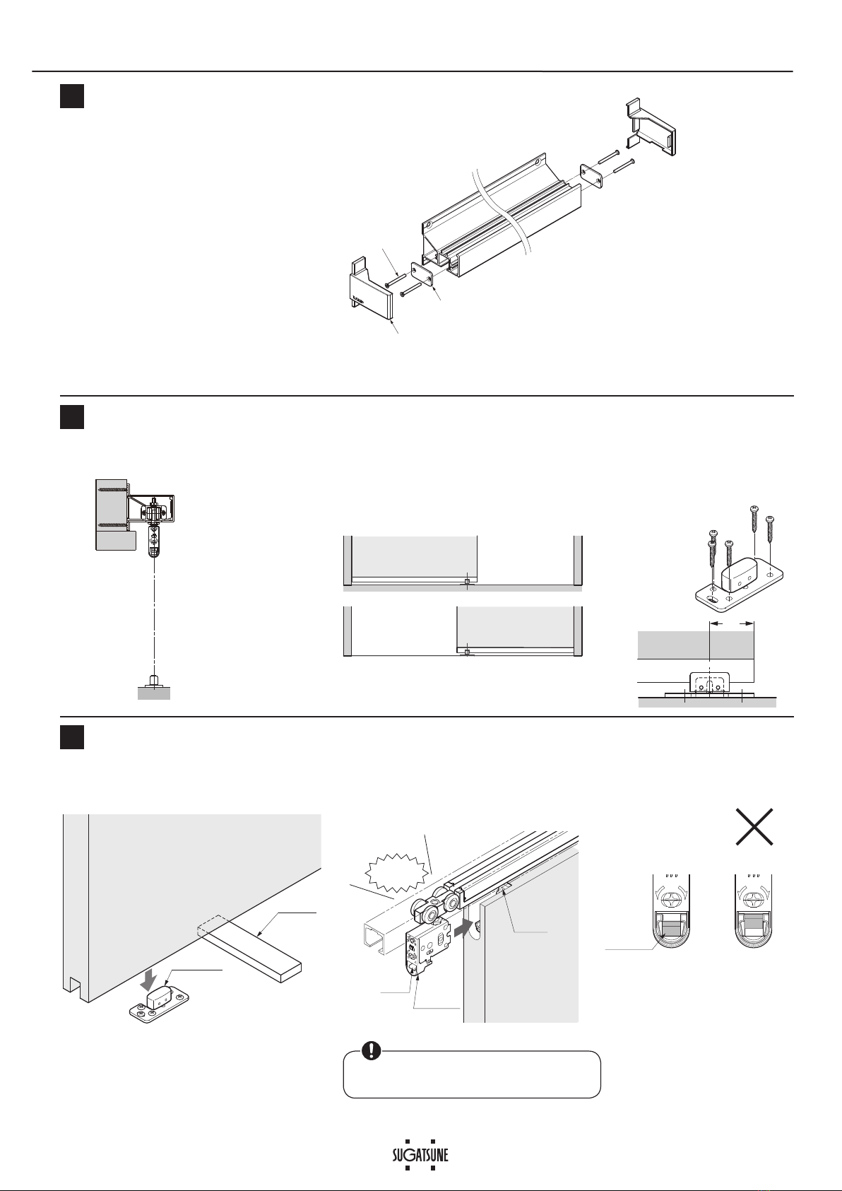
This (sliding door system) should be installed by a qualified person. If the system is not installed correctly, the door will not
operate smoothly, and may cause injury.
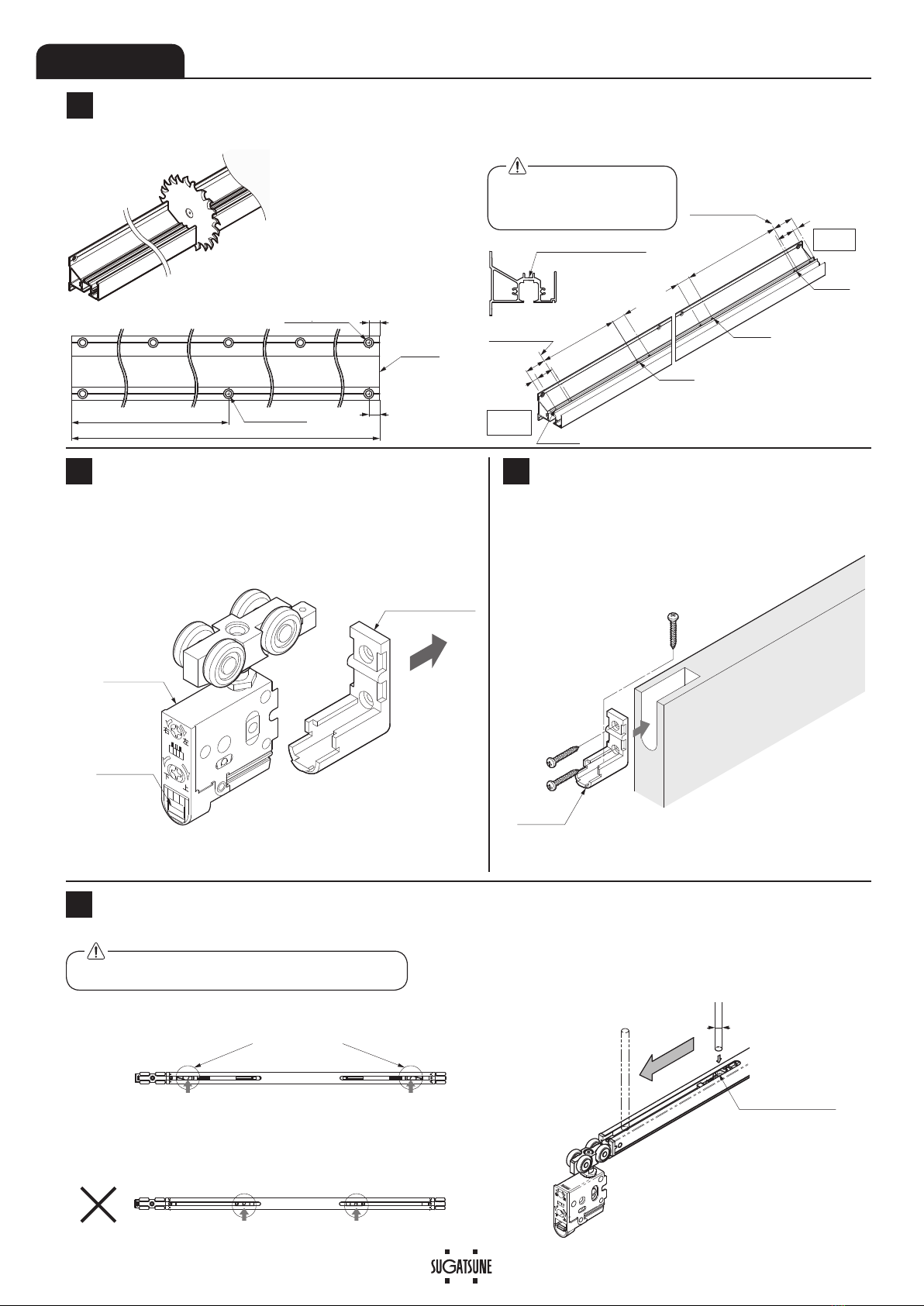
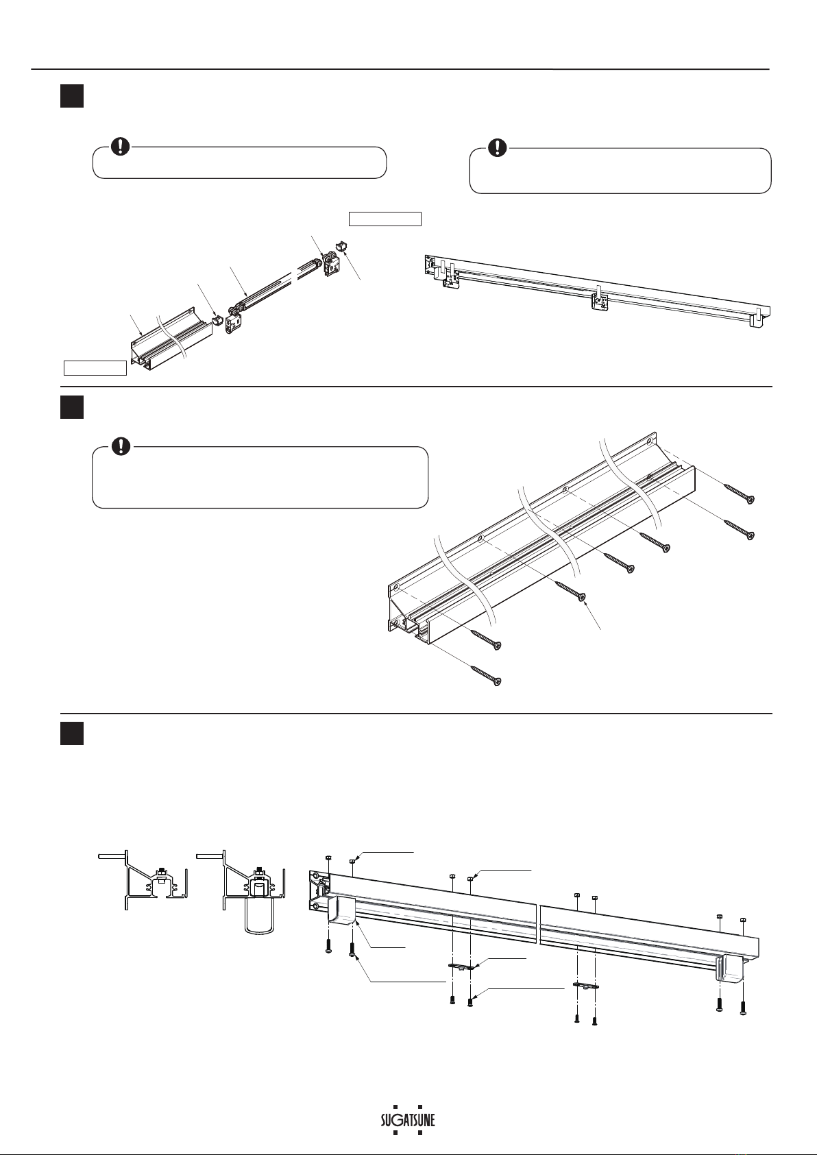
It is necessary to manufacture the frame with sufficient strength so that it endures the weight of the door and any impact
upon opening/closing the door. Only use designated screws and ensure that they are fastened firmly. A frame with poor
strength or loose screws might result in the door falling and causing injury.
Do not try to use this product for anything other than its original purpose. Do not use any part for applications outside of its
specification.
Do not disassemble nor modify any parts other than those described in this document.
Make sure to follow the designated dimensions, specifications, and horizontal/vertical angles. Make sure that the frame is
not warped, since it may affect the movement of the door.
If cutting any parts, make sure to remove any burrs before installation. Also check the upper track for any left-over burrs or
scraps and remove these.
This product is a part for architectural fittings. After installation, make sure to test the finished product thoroughly to ensure
that it is well-functioning and safe. Please inform the end user about general precautions and safety to prevent improper use.
Make sure to check the screws for slack at regular intervals (one month from first usage, half a year, and then one time
every year is recommended).
Prohibited
Warning
Caution Required
Meaning of symbols
FD50H SLIDING DOOR SYSTEM Installation Manual
2XWVHW7\SHZLWK7ZRZD\VRIWFORVH
PartNo:FD50DHCP-AK
●
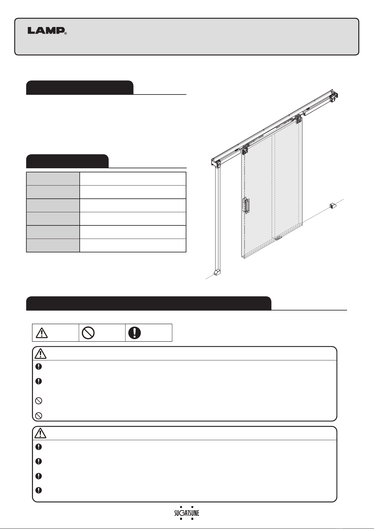
This product is a parts set for an overlay indoor sliding door
system.
●
The door closes in a 2 soft motion steps; first slow, then
fast, and opens with a 1 step soft motion.
●
Easy door installation and adjustment.
Thank you for selecting our product. Before starting installation, please read this manual thoroughly to ensure correct installation.
Please keep this manual at hand for future reference.
Max. Door height
2400mm
Max. Door width
680 − 1500mm
0LQ'RRUWKLFNQHVV
30
−
36mm
Max. Door weight 50kg※1
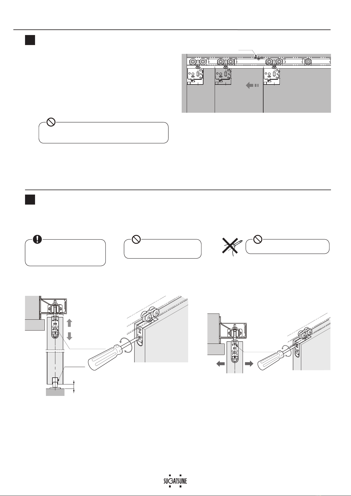
9HUWLFDODGMXVWPHQW
3mmupward,4mmdownward
)URQWUHDUDGMXVWPHQW
± 2mm
ABOUT THE PRODUCT
SPECIFICATIONS
FOR YOUR SAFE WORK AND CORRECT INSTALLATION
The closing speed of the soft closing type door may change due to
ambient temperature, operating method or installation quality.
・
Recommended ambient temperature range is 5 to 40°C.
※1
If a light weight door is applied, you may feel the resistance
of the soft closer when opening the door.

2
12※
3
1
5
※3
47.5
16
45※²
⑬Cover cap
(Option)
47
2
⑫
Door guide track
(Option)
15
17
Trigger
2pcs
Triggerjig
1pc
№ ①②③④⑤⑥⑦⑧
Name Upper track Side cover Stopper plate
Screw for stopper
plate
Soft Closer Trigger&
TriggerJig
Screw & nut
for trigger Upper roller
Item No. )'75$ )'+$6&
)':5+'6&
)'75-、
)'75*
)'75$75*1
)':5+
Item
PP
Hole pitch:
PP
Pitch end: 10mm
Single sliding
1 pc L/R1 ea 2pcs 4pcs 1 pc 1set 2 set 1 pc
№ ⑨⑩⑪⑫
Name Bumper block Floor guide Door stopper
ÀRRU
Door guide
track
Item No.
)'75$673
)'%*
)'(9)673
)'+%576,/
Item
Single sliding
2 pcs 1pc 2 pcs 1 pc
237,21$/3$576
⑬
Cover cap
)':5+&3
50
10
10
36
10
10
64
18
3
41
32
12 40
18 40 12
50
18
5
8
2
5
76
10
1
8
9
797
7
6
7
12
36
28
2
10
6
15
28
48
28
4
62.5
35.5
3.6
61.6
46.5
7.5
15
34.6
9
(10.5)
(7)
15
17
Door height DH
DH+
13
1.8
13.5
9
When using
HH-P135
recessed pull
11
Door close
position
3
Door open
position
20
16.5
Track length
Track length/2
215 [217]※₂
I5.6I9 CSK
Hole pitch 300
Door width DW
Door open
position
I5.6I9 CSK
fortrigger
DW−412 [DW−414]※₂
3
11
2
Leading
edge
Trailing
edge
9
※₂[ ]WhenCovercap⑬(Option)isused.
COMPONENT PARTS
※2
When FRYHUFDS⑪(2SWLRQ
is used
※
:KHQXVLQJGRRUJXLGHWUDFN⑫
(Option)
'RRUSURFHVV
dimensions
,167$//$7,21'5$:,1*(;$03/(
ACCESSORY:Spanner)')63
×
Countersunk head tapping
VFUHZVî'SFV
7KHSDUWVEHORZZKLFKDUHSDFNHG
ZLWKVRIWFORVHU①are not needed
IRUWKLVDSSOLFDWLRQ
Countersunk head
tapping screw 4×40
Accessory screw:
Countersunk head screw
î'
Accessory screw:
Bind head tapping
screw
î・・・・・・・ 5 pcs
Accessory screw:
Pan head tapping
VFUHZî・・・・ SFV
Accessory screw:
Panheadtappingscrew4×252pcs
panheadscrewM4×162pcs
NutM4 2pcs
Hole pitch:
250 mm
3LWFKHQGPP
Countersunk head
WDSSLQJVFUHZVî
Screws for stopper plate are attached to ③above.
(2 pcs/set)
Accessory screw:
Countersunk head tapping
VFUHZî'・・・・・・4 pcs
Accessory screw:
Pan headtapping screw
î・・・・・・・SFV
Accessory screw:
Countersunk head screw
î'・・・・・・2 pcs
Nut M4 ・・・2 pcs
Accessory screw:
Pan headtapping screw
î・・・・・・・SFV
t=2

3
I6
Trigger catcher
(Red colored part)
❶
❷
Main unit
Pull out casing
Pull up
lever
Casing
Correct set position
Incorrect set position
Trigger catcher
(Red colored part)
Correct set position
OK
Trigger,Bumper block
Track length
Track length /2I5.6I9 CSK
I5.6I9 CSK
10
10
Cut end
2×
I4.5
2×
I4.5
2×
I4.5
50
※
4
18
206
40
※4 Door close
position
12
※
4
2× I4.5
18 DW−421 50
※
4
40 12
※
4
※4Door open
position
Leading
edge
Trailing
edge
ASSEMBLY
1&XWWLQJDQG3URYLGLQJ+ROHRQ8SSHU7UDFN
)DVWHQWKHFDVLQJ¿UPO\ZLWKWKHSURYLGHGVFUHZVRecessed roller: Separate main unit from casing.
Preparation of mounting parts
2Installing Casing
3
9HUL¿FDWLRQ%HIRUH,QVWDOOLQJ6RIW&ORVHU
4
:LWKRXWYHUL¿FDWLRQWKHVHOIFORVLQJIHDWXUHPD\IDLO
If the position is wrong, pull back the trigger catcher to
WKHFRUUHFWSRVLWLRQXVLQJDPPGLDPHWHUURXQGEDU
+ROHSURFHVVLQJ
Cutting 3URFHVVLQJKROHVIRUWULJJHU
Take care of the direction of
upper track
(leading edge, trailing edge).

4
①Upper track
⑨Bumper block
⑤Softcloser
⑧Upper roller
⑨Bumper block
❶
❷
❸❹
Countersunk tapping screw
4x40 (provided)
⑥Trigger
Bumper
block
Pan head screw
4×16 Countersunk head
screw 4×10(D6)
NutM4
(accessory) NutM4
(accessory)
5,QVHUWLQJ3DUWVLQWR8SSHU7UDFN
)L[LQJ8SSHU7UDFN
6
Installing Trigger,%XPSHUEORFN
7
Verify that the upper track is set horizontally before
fastening.
Remove any dirt or aluminum chips from the track.
Insert the parts in order from ❶to ❹with care of direction.
Fasten triggers to the hole made during procedure 1
with the provided nuts.
1
Leading edge
Trailing edge
Fasten bumper blocks temporarily to prevent the
inserted parts from falling.
Remove any dirt or aluminum chips from the track.

5
Fully closed
Fully opened
Leading edge Trailing edge
上
下上
下
Lever is on
the bottom
Support
Floor guide
Lever
Casing
Roller
(main body)
CLICK
OK
②Side cover
④Provided screw
③Stopper plate
下上
左
右
Door (trailing edge)
32
8
9
Assembling Side Cover
Fixing Floor Guide Temporarily
Hanging Door
10
Position floor guide just below the
center of upper track.
Put a 10 mm support under the door.
:KLOHKROGLQJWKHGRRULQVHUWWKHÀRRU
guide into the groove under the door.
3RVLWLRQWKHÀRRUJXLGHVRWKDWLWVUROOHUSDUW
stays under the door when it is opened or
closed.
Insert the recessed roller into the casing until a
“click” sound is heard.
Fasten temporarily through the
elongated hole and adjust the
SRVLWLRQ7KHQIDVWHQWKHÀRRU
guide through the rest of the four
holes.
Verify that the roller is not dislocated from
the casing, for both door sides.

6
右
上
下
左
Front-rear adjustment
screw
2 mm
2 mm
右
上
下
左
Clockwise: raise
Counterclockwise: lower
6‑13
Floor guide
Vertical adjustment
screw
4 mm
3 mm
$GMXVWLQJ'RRU3RVLWLRQ
The of the door should be
done with the jump prevention
nut loosened.
12
Vertical adjustment range: 7 mm )URQWUHDUDGMXVWPHQWUDQJH:4 mm
Do not use electric screwdriver.
9HUL¿FDWLRQRI6RIW&ORVHU2SHUDWLRQ
11
Remove the 10 mm support from under the door.
7KHVRIWFORVHULVHQJDJHGDSSUR[LPDWHO\ PPDW
the leading edge (or 50 mm at the trailing edge) before
WKHGRRUUHDFKHVLWV¿QDOSRVLWLRQ
Please refer to the “Troubleshooting” section. when the
soft closer does not work correctly.
'RQRWFORVHWKH GRRUZLWKH[FHVVLYH IRUFH,WPD\
cause damage to the soft close mechanism.
$GMXVWWKHGRRUSDUDOOHOWRWKHXSSHUWUDFNZLWKPPRIFOHDUDQFHEHWZHHQWKH
GRRUDQGÀRRU
Trigger
Do not turn adjustment screw
beyond adjustment range.

7
Jump prevention nut
Tighten
Pan head tapping
screw
4×30
Door stopper
unit
⑪Door stopper
(floor)
Door open
position
⑪Door stopper
(floor)
⑪Door stopper
(floor)
Door close
position
Fastening the Jump Prevention Nut
13
,QVWDOOLQJGRRUVWRSSHUÀRRU
14
The jump prevention nut is on the hanger bolt of the recessed roller.
Tighten the nut with the provided spanner until it contacts the soft closer.
Fasten door stoppers at the positions where the door stops.
Be sure to tighten the nut
to prevent damaging parts

8
Spanner
Lever
How to remove door
PERIODICAL
INSPECTION
・Clean inside of track.
・Check upper and lower gaps between the door and frame. If necessary, adjust the gaps.
)LQDOYHUL¿FDWLRQ Verify that all screws are securely tightened, and verify that all screws have been used.
Supplement
Pay attention not to let the door fall.
Use a 10mm support under the door.
Then pull out the upper roller main unit from the door while raising
the lever.
It will be easier if you slide the hanger bolt with a spanner.
Trouble Checkpoint Solution
Door stops during soft
closing.
&KHFNLIGRRUERWWRPFRQWDFWVWKHÀRRU
9HULI\WKDWWKHWUDFN¿[LQJVFUHZVDUHQRWORRVHQHG
Then, adjust the door height such that the clearance between the door bottom
DQGÀRRULVPP
Check if upper track is set horizontally. Using a level gauge, reset upper track horizontally.
Check if mohair seal is installed. Reduce the friction between mohair and door.
No soft closing Check if trigger is installed. Install trigger to correct position.
&KHFNLIGRRULVFORVHGE\H[FHVVLYHIRUFH 'RQRWFORVHGRRUE\H[FHVVLYHIRUFHDVLWPD\GDPDJHVRIWFORVHU
The position of the trigger catcher may become
dislocated. (See section 4.)
&KHFNWKHVWDWXVRIWKHWULJJHUFDWFKHULQ3VHFWLRQ
Abnormal noise during
operation &KHFNLIGRRUERWWRPFRQWDFWVWKHÀRRU
9HULI\WKDWWKHWUDFN¿[LQJVFUHZVDUHQRWORRVHQHG
Then, adjust the door height such that the clearance between the door bottom
DQGÀRRULVPP
Check if door touches adjacent parts. Provide necessary space between door and adjacent objects.
Check track rollers for aluminum dust. Remove the track and pull out the roller. Then, clean the roller.
Check for loose screws retaining the upper track. Tighten the screw.
Heavy door operation Check if door touches adjacent parts. Correct door position to avoid contact with other objects.
$GMXVWSRVLWLRQRIÀRRUJXLGHRUVWRSSHU
&KHFNLIGRRUERWWRPFRQWDFWVWKHÀRRU
9HULI\WKDWWKHWUDFN¿[LQJVFUHZVDUHQRWORRVHQHG
Then, adjust the door height such that the clearance between the door bottom
DQGÀRRULVPP
Door starts to move. Check if the upper track is set horizontally. Using a level gauge, reset upper track horizontally.
■TROUBLESHOOTING
SUGATSUNE KOGYO CO.,LTD
Tokyo, JAPAN
SUGATSUNE KOGYO (UK) LTD
Reading, UK
Phone: +44 118 9272 955
E-mail:[email protected]
SUGATSUNE EUROPE GmbH
Dusseldorf, GERMANY
Phone: +49 211 53812900
E-mail:[email protected]
SUGATSUNE SHANGHAI Co., LTD
Shanghai, CHINA
Guangzhou, CHINA
SUGATSUNE KOGYO INDIA PRIVATE LIMITED
Mumbai, INDIA
SUGATSUNE AMERICA, INC
California, USA
Chicago, USA
Phone: +1 312 461 1081
E-mail:[email protected].
SUGATSUNE CANADA, INC.
Phone: +1 514 312 5267
E-mail:[email protected]
2019.02 1291-1
Other manuals for LAMP FD50-H
3
This manual suits for next models
1
Table of contents
Popular Garage Door Opener manuals by other brands

Amarr
Amarr 4200 installation instructions

Nice
Nice Spido Instructions and warnings for the fitter

CAME
CAME 119BW41EN installation manual

tau
tau T-SKY Use and maintenance manual

Motorline professional
Motorline professional KVM2020 installer and user manual

Security Brands
Security Brands RTE 300 Series quick start guide